
This is part 2 of a series of posts about building an Apple-1 reproduction in 2024. See also:
- Building an Apple-1 Reproduction in 2024 - Part 1: Components
- Building an Apple-1 Reproduction in 2024 - Part 3: The Retro Chip Tester
- Building an Apple-1 Reproduction in 2024 - Part 4: Assembly
- Building an Apple-1 Reproduction in 2024 - Part 5: Monitor, Keyboard, Power-Up
- Building an Apple-1 Reproduction in 2024/2025 - Part 6: C Programming
- Building an Apple-1 Reproduction in 2024/2025 - Part 7: The Audio Cassette Adapter
Introduction
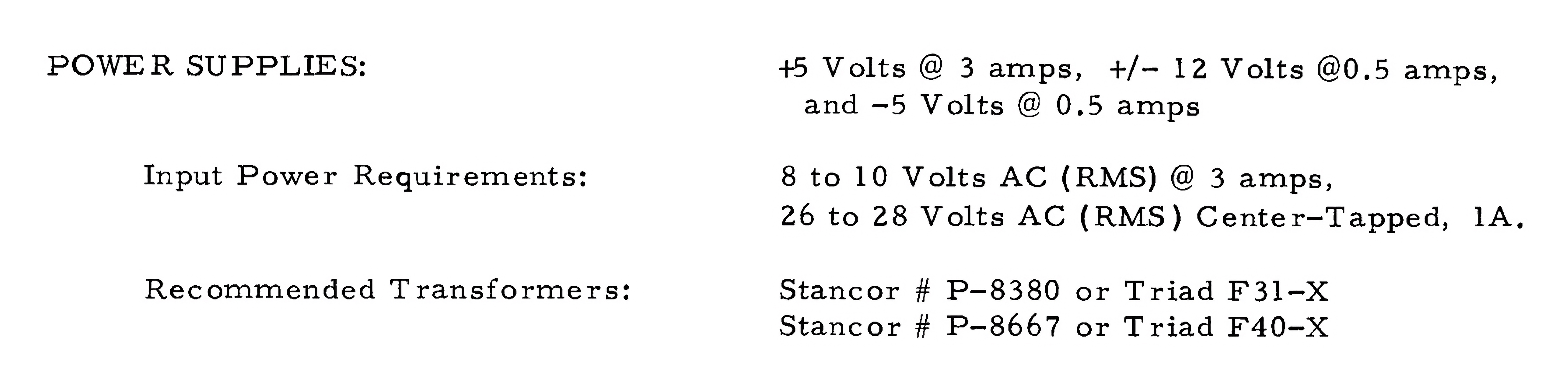
Every computer needs a power supply. On the Apple-1, it is split into two parts:
- Separate from the main board: two transformers, fuse, switch, wiring to the mains and to the main board.
- On the main board: rectifier diodes, capacitors, and regulators.
You can see these two parts represented in the following schematics:
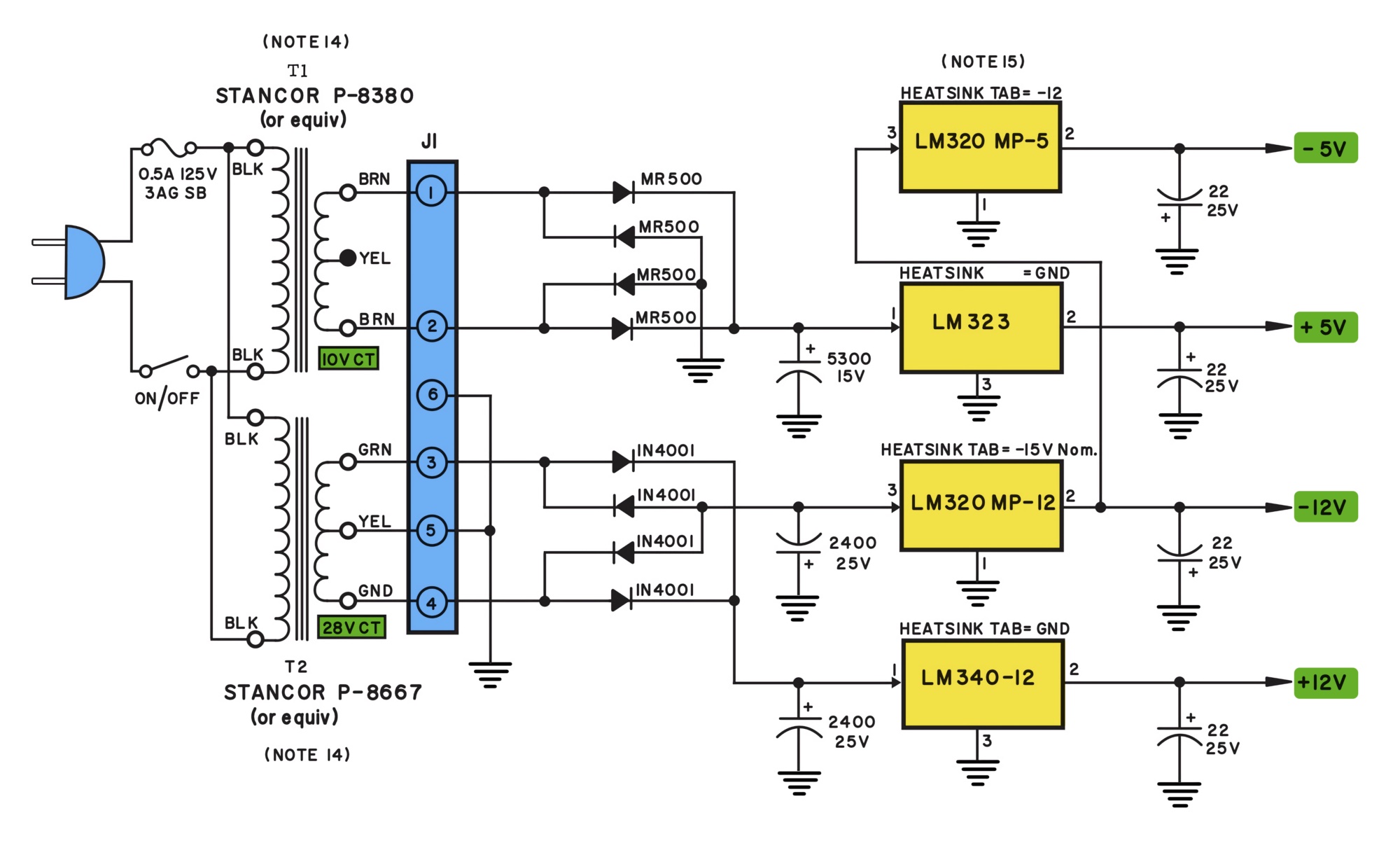
Credit: Apple-1 schematics redrawn by Armin Hierstetter, colorized by myself.
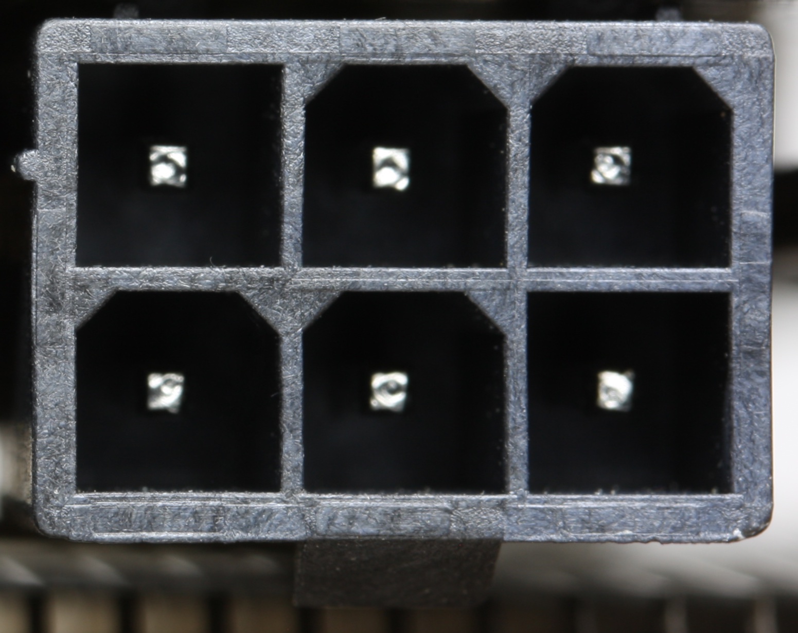
The main board features a 6-pin Molex connector, identified by J1, to which the output of the transformers is connected.
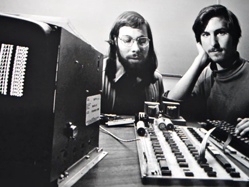
On many original Apple-1s, you can see the two transformers in the open, simply mounted on a separate wooden base. There are even some iconic photos of Steve Wozniak and Steve Jobs with the Apple-1, where you can see the transformers on such a base.
Modern approaches
In 2024, you could instead use a modern power supply. People have adapted, in particular, MEAN WELL power supplies. This is good because:
- it is more power-efficient;
- it can be safer as the power supply is fully enclosed;
- it is smaller and lighter.
I have seen online two beautiful examples of such power supplies, including one by Armin in Germany, and one by Arunas in Lithuania. I don’t rule out that I will try something like this in the future.
Choice of enclosure
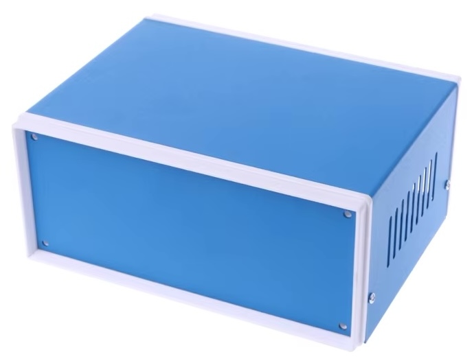
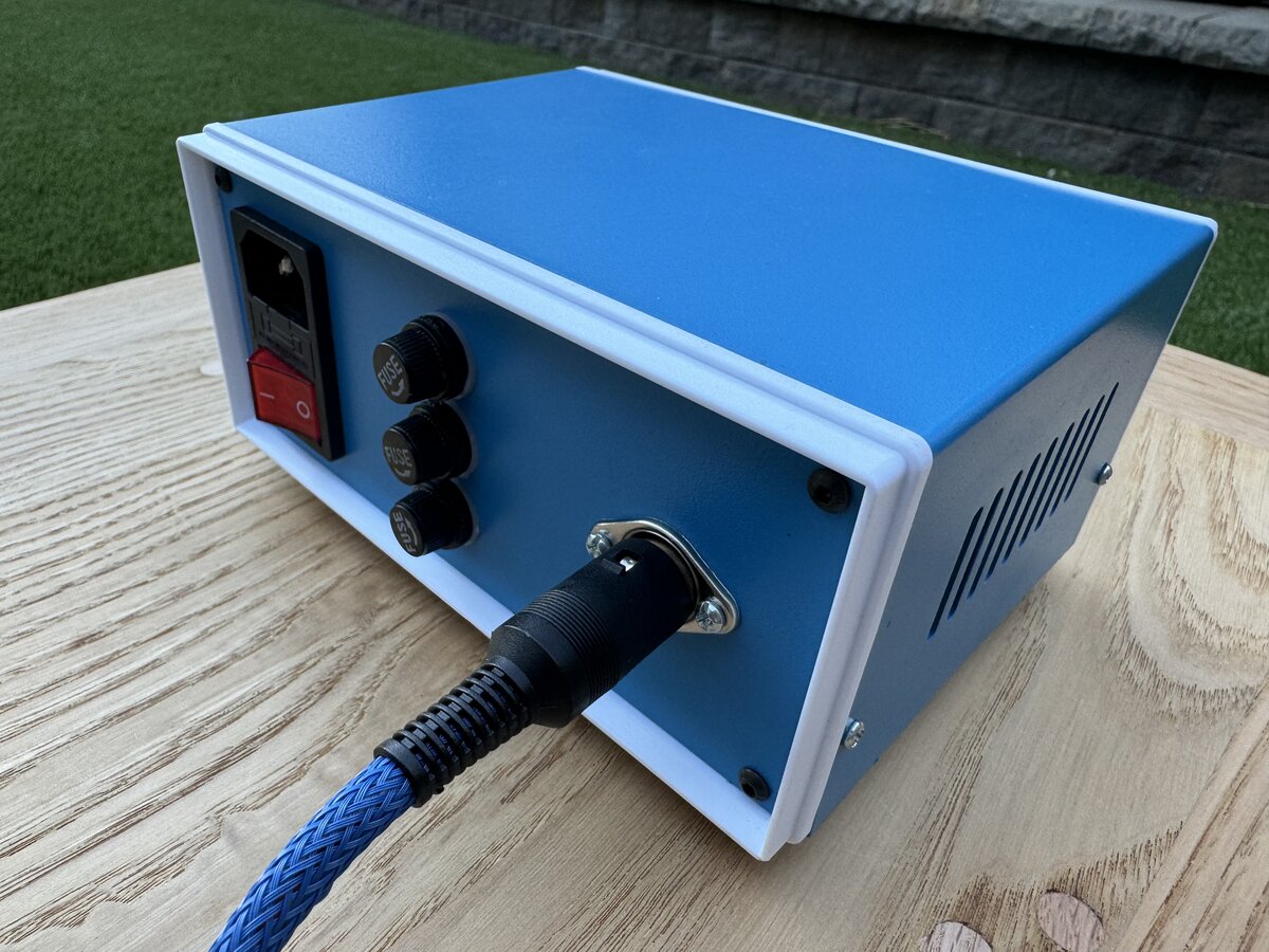
I have to recognize that the transformers on a wooden board have some appeal! But for now, I wanted to go with the original transformers. However, for practical and safety reasons, I decided that I wanted to enclose the transformers and associated hardware.
I came across those inexpensive but fairly pretty blue metal (with white plastic parts) cases. The case has front and back panels, a removable top panel, vents on the left and right side, and rubber feet. This one was $12.44 shipped from AliExpress. Note that while it comes with the screws to attach the top panel, it doesn’t come with screws to attach the front and back panel and you have to provide those yourself.
My plan was to mount my transformers inside, but also to use the opportunity to include some enhancements sometimes recommended by the Apple-1 community:
- secondary fuses
- secondary LED indicators
The secondary fuses are not present in the Apple-1 schematics, but they are an obvious protection in case of serious problem. They are in particular recommended by Uncle Bernie on the AppleFritter forums.
The LED indicators are not present in the schematics either, but I think they are pretty cool, and they indicate that the power supply is on and working and that the fuses have not blown up.
Transformers
As mentioned in Part 1, I obtained two Triad Magnetics transformers from Mouser.
- The large transformer is a Triad F-31X which outputs 10 V up to 3.0 A.
- The small transformer is a Triad F-40X which outputs 26.8 V up to 1.0 A, with a center tap.
These are brand new, made in Philadelphia (the stickers say “Made in PHL”).
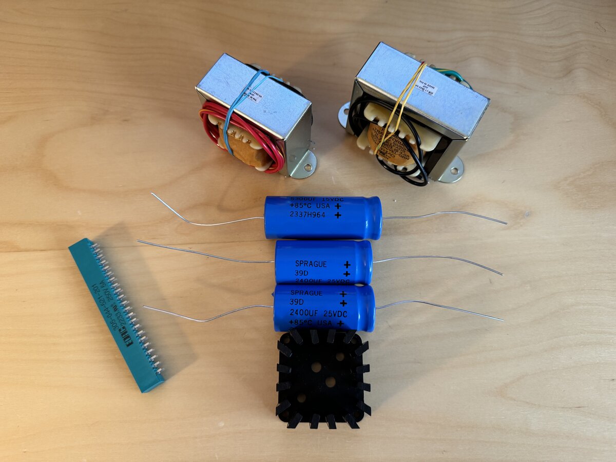
The original Apple-1 manual actually recommends Stancor or Triad transformers, so this is as good as it gets.
Design and prototyping
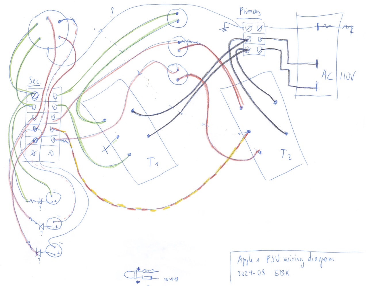
I started with a very crud wiring diagram, which I barely dare show here.
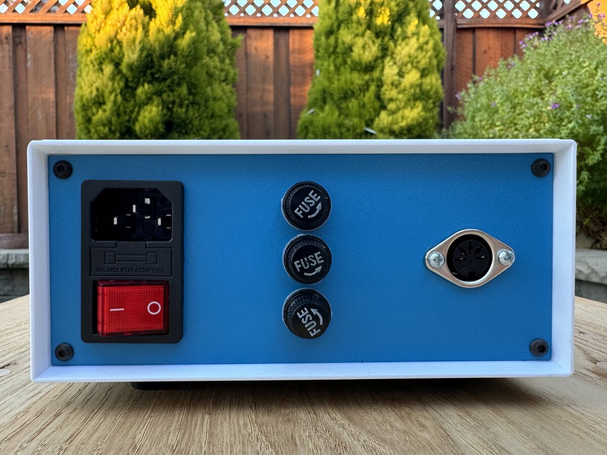
Then I prototyped the panels in cardboard, to make sure each component would have enough clearance. Here is a view of the back with the power entry, fuse holders, and power output connector.
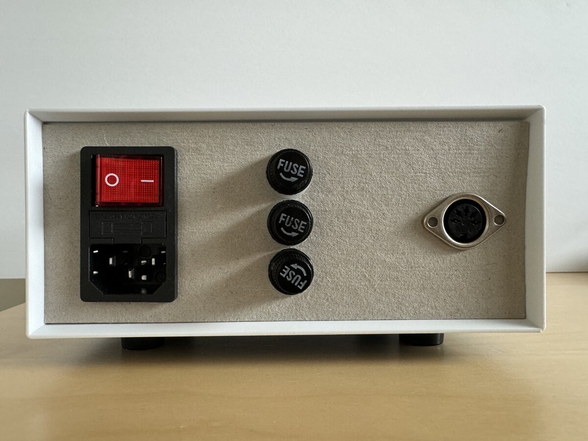
I planned to use DIN connectors for the output:
- 5-pin female DIN on the chassis
- 5-pin male DIN on the cable
The pinout would be entirely custom. Even though the Apple-1 schematics show a 6-pin connector, 5 pins are enough for the two transformers secondaries, plus one wire for the center tap, which becomes the “ground” on the Apple-1 board.
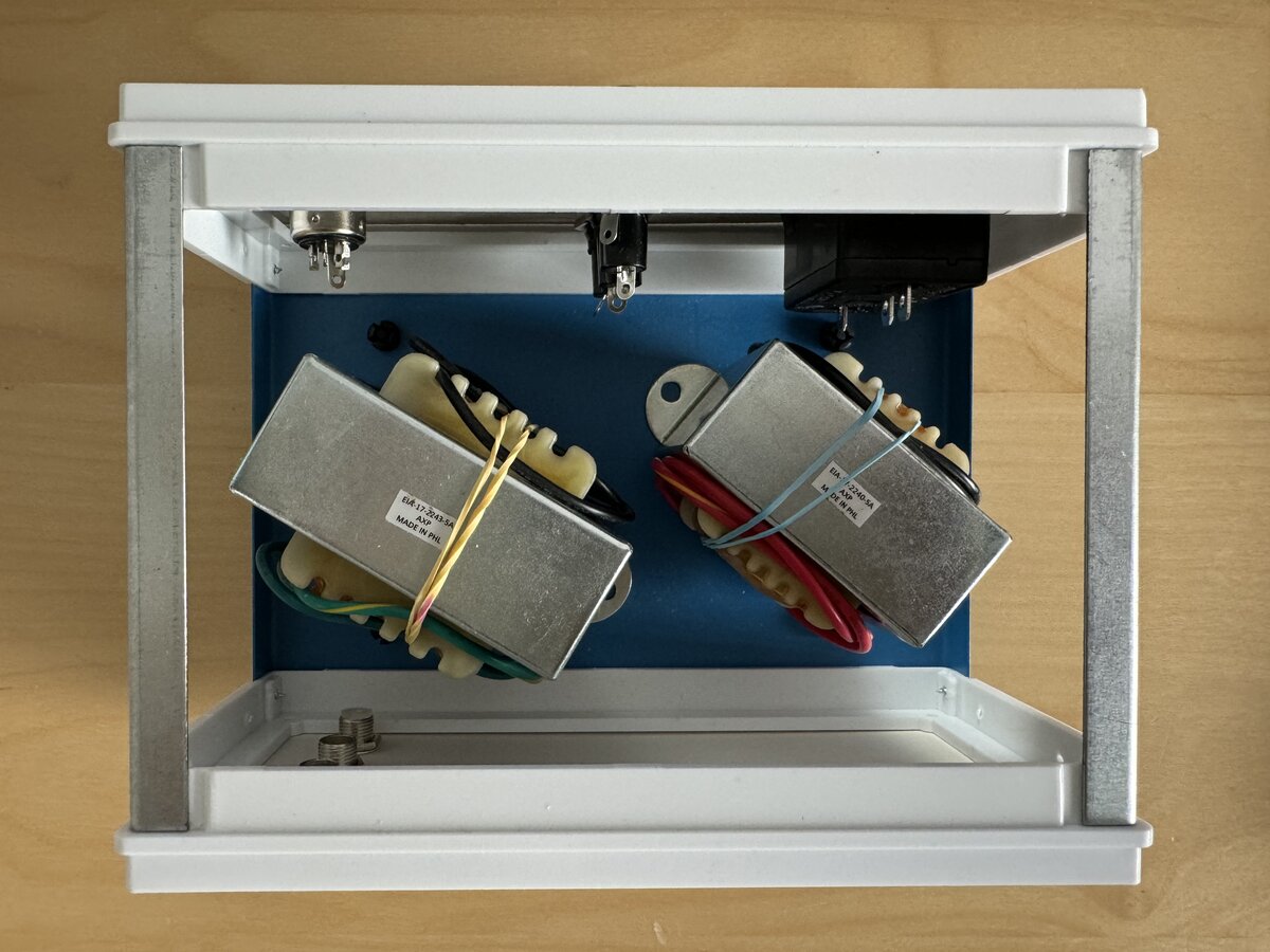
I made sure the transformers and other parts would fit without problems. I placed the transformers sideways to optimize the space.
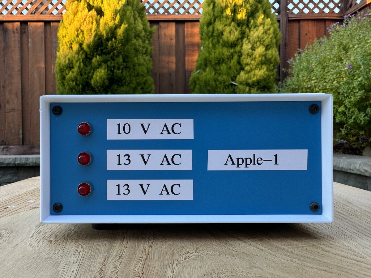
Front panel
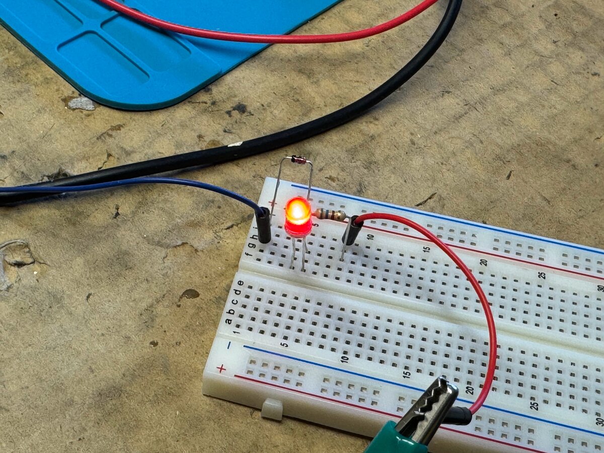
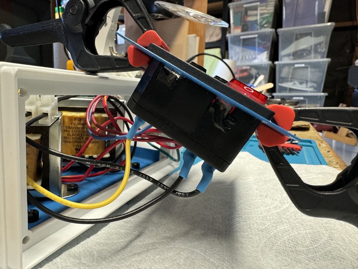
I wanted to have LED indicators for the transformer secondaries. For this, you need an LED, resistor, and signal diode as the output of the transformers are AC and an LED is polarized. With this, the LEDs will blink at 60 Hz (but you will not see it unless you try to take a picture or video). I prototyped this on a breadboard first as I wanted to be sure I used adequate resistor values. Here is what I used:
- 3 × 1N4148 diodes
- 10 V secondary: 1 × 390 Ohm resistor
- 13 V secondaries: 2 × 560 Ohm resistors
UPDATE: I was asked about the reason of the presence of another diode in addition to the LED. After all, an LED is also a diode (it’s in the name: Light Emitting Diode), so even with AC, things should work. To be fair, I had seen that design with an additional diode before, and it seemed to make sense and didn’t think twice about the diode. Here is the explanation:
The LED is connected to AC so there is a reverse voltage half of the time up to about 10 V or 13 V. The datasheet for standard LEDs mention a max reverse voltage supported of 5 V, so without doing anything more we would be exceeding that spec. Using a signal diode, we protect the LED against such excessive reverse voltage. A 1N4148 for example support around 100 V reverse voltage, so it will block in the reverse direction without any problem. I imagine that in practice, an LED might support a higher reverse voltage than 5 V, and things might still work without an extra diode, but based on the datasheet values, extra protection for the LED is warranted.
After drilling holes for the LEDs, I mounted them on the front panel with holders. I soldered the resistors and diodes directly on the LED pins.
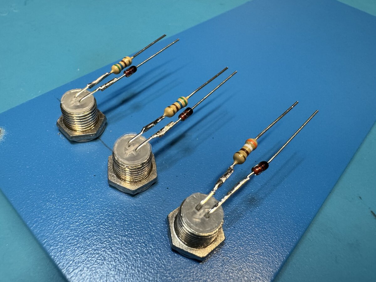
I used heat shrink tubing to protect the connections.
Here I am testing that the LEDs work.
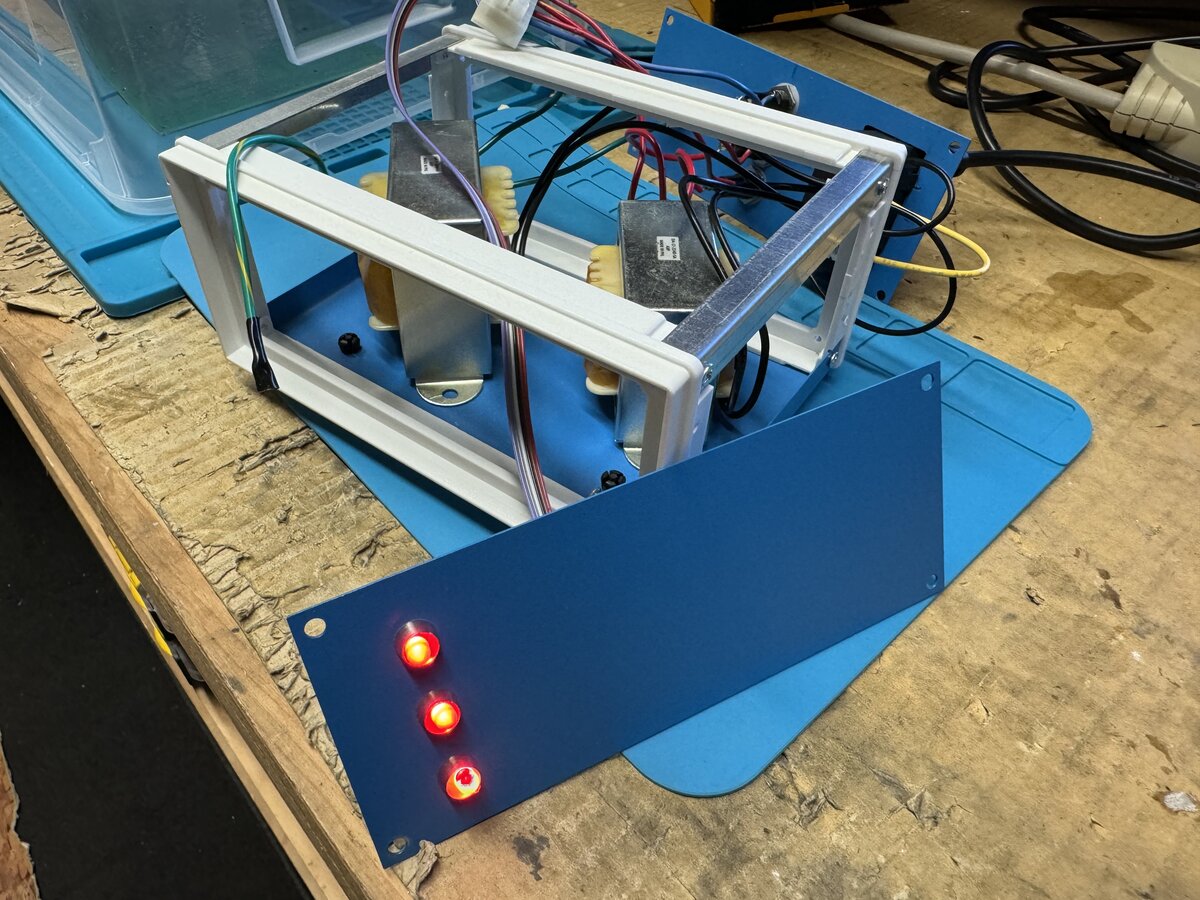
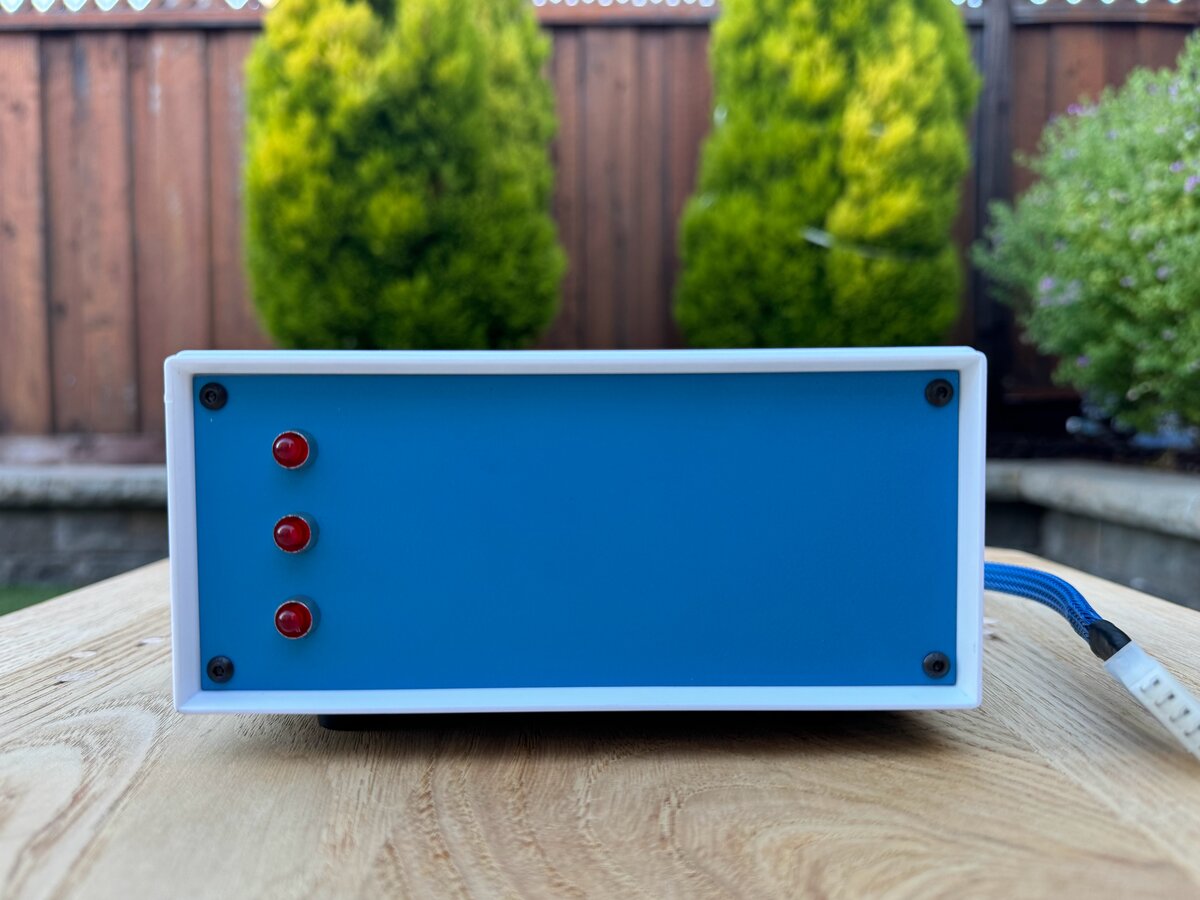
Here is the result from the front after screwing the front panel.
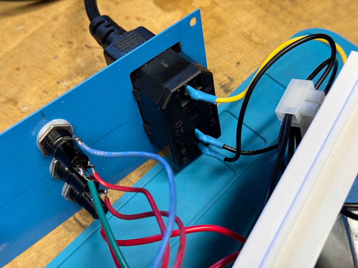
Back panel
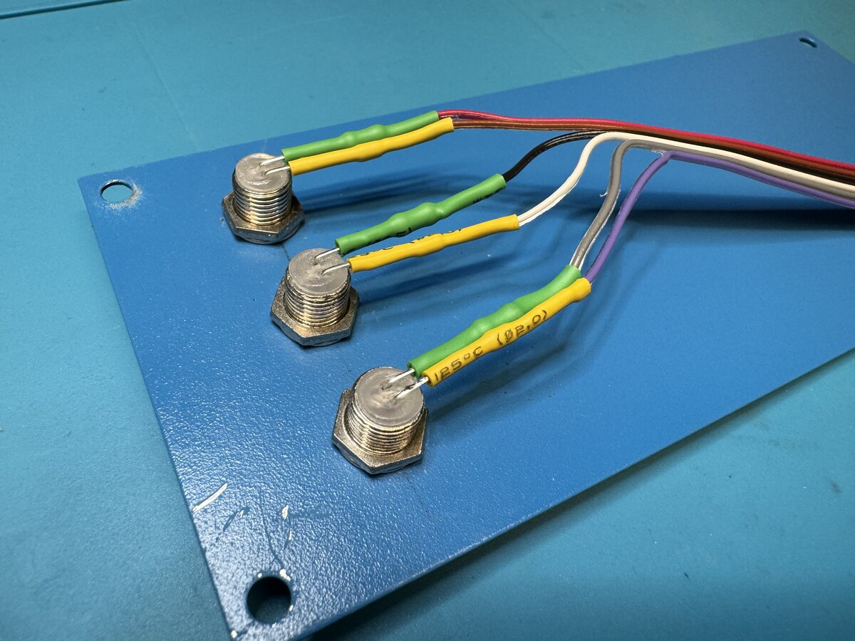
For space reasons I had to use the small and common 20 mm × 5 mm fuses, as well as the matching holders, instead of the larger 3AG fuses that one might have used if just mounting the transformers on a wooden board. The use of these holders allows you to easily change the fuses from the outside of the case. The space inside the box is very limited anyway, and this seems to be a better design. Of course, one hopes that you will never have to actually change a blown fuse as that would indicate a serious problem happened! I followed advice on Apple-1 forums to use:
- 1 × 0.5 A fuse for the primary, which fits in the power entry assembly
- 3 × fuses for the secondaries
- 2 × 1 A slow blow for the small transformer that will feed the -12 V/-5 V and +12 V supplies on the board
- 1 × 3 A slow blow for the large transformer that will feed the main +5 V supply on the board
I drilled/cut/filed the metal for the back panel. This was a pain as I don’t have a drill press or a good metal saw. So I used a hand drill, Dremel, and a file. But it worked out.
I then worked on the female DIN connector, but I had trouble with the specific one I had bought. It was too cheaply made and I didn’t trust the connections. Still, I tried soldering wires to it.
However, I decided to abandon this specific connector and to have the cable go out of the case without a connector, just through a grommet, as a temporary solution.
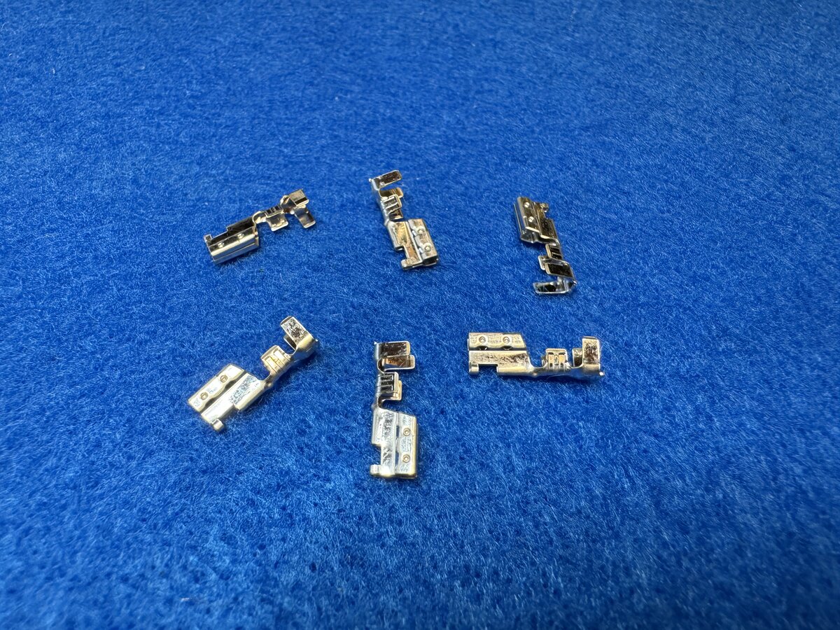
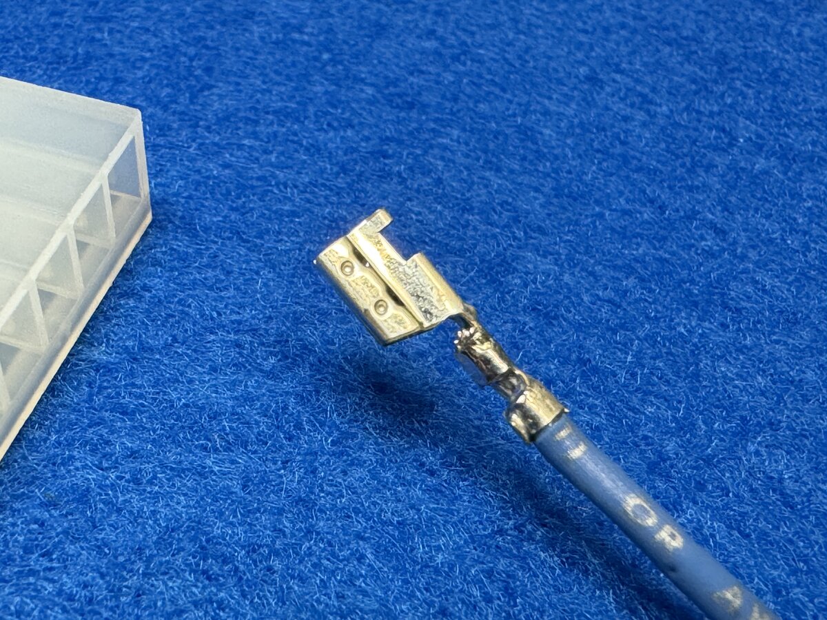
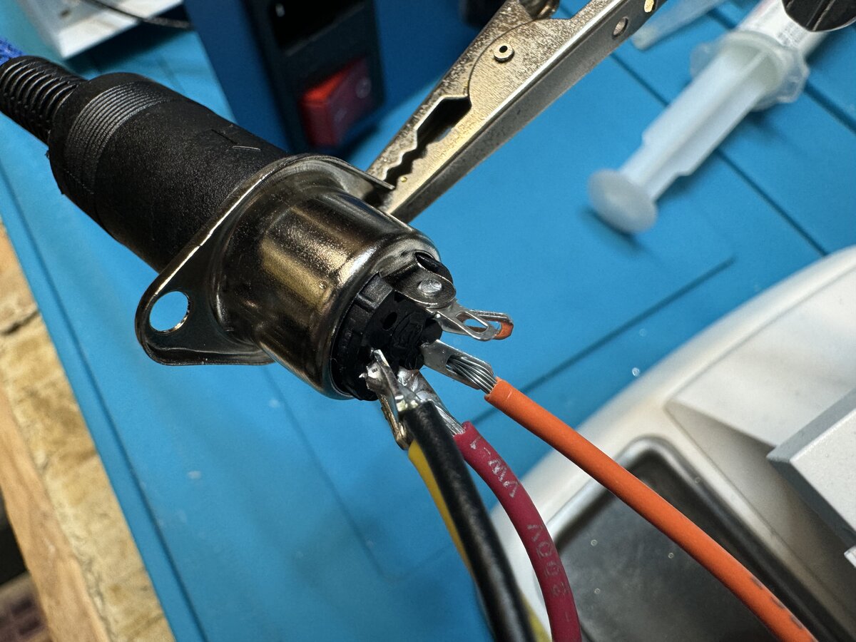
I assembled the Molex connector easily. The metal parts (“SPOX Crimp Terminal, 18-24 AWG, Brass, Reel”) need to be cut from a roll.
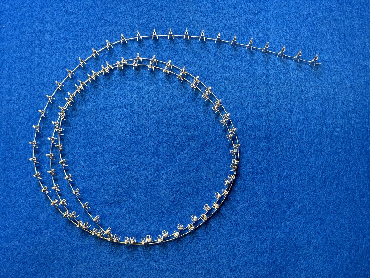
Here are the cut parts.
While I crimped them with small pliers, I also soldered the wires (I realize that there is possible debate about that).
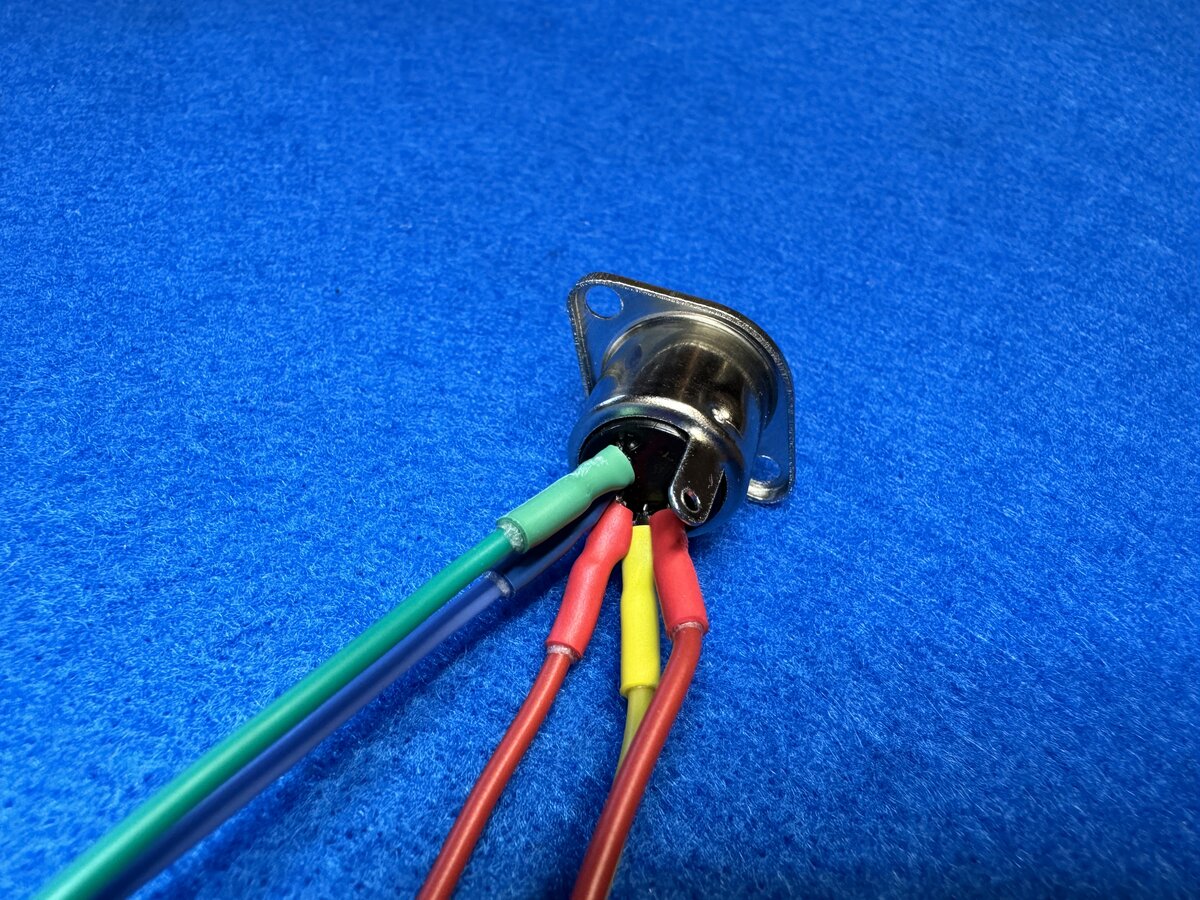
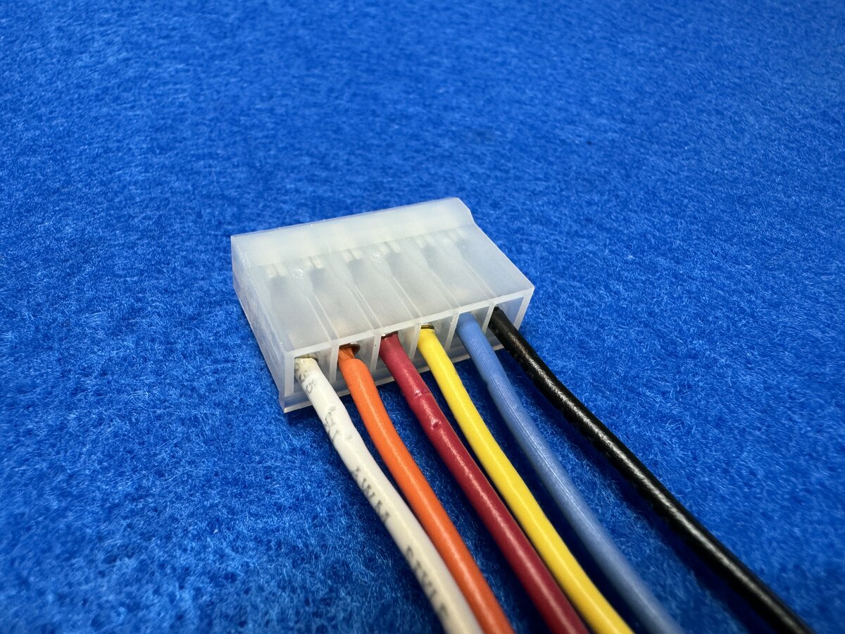
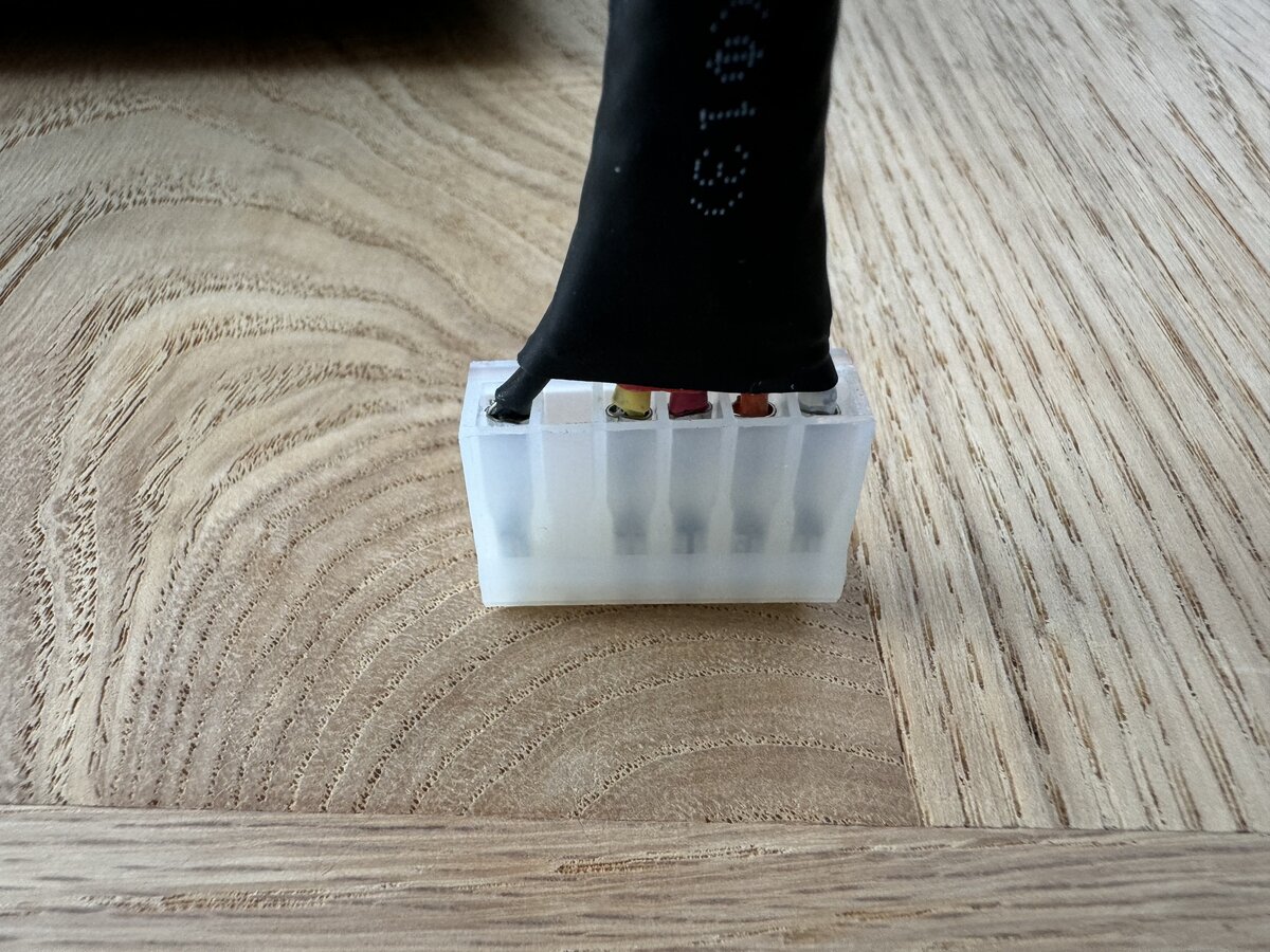
Here is the female connector (“3.96mm Pitch SPOX Crimp Housing, Female, with Friction Ramp, 6 Circuits, Natural”) with its six wires installed.
NOTE: I later removed wire #5, see further below.
I then used a sleeve and heat shrink tubing over the end:
Here is the result after screwing the back panel in place. You can see that the output cable just goes through the hole meant for the DIN connector.
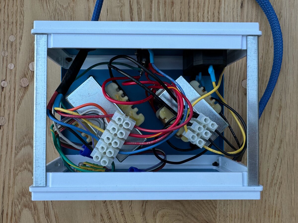
Here is the inside view from the top after both panels were installed.
Reworking the cable
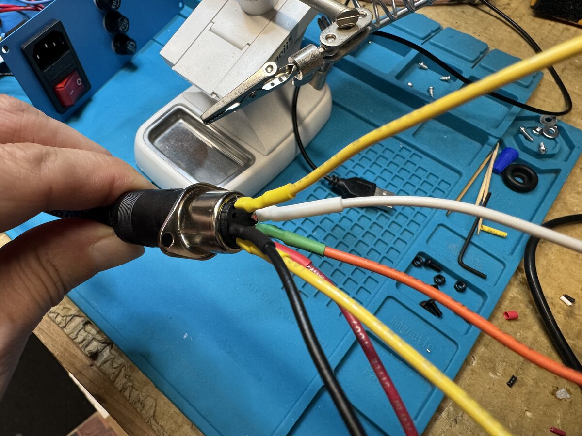
I could have stopped there, but I was not satisfied with my initial cable and connectors. I decided to order a new female DIN connector from DigiKey (which costs a large multiple of the ones bought from AliExpress). And it does feel sturdier, with the pins also better laid out for soldering.
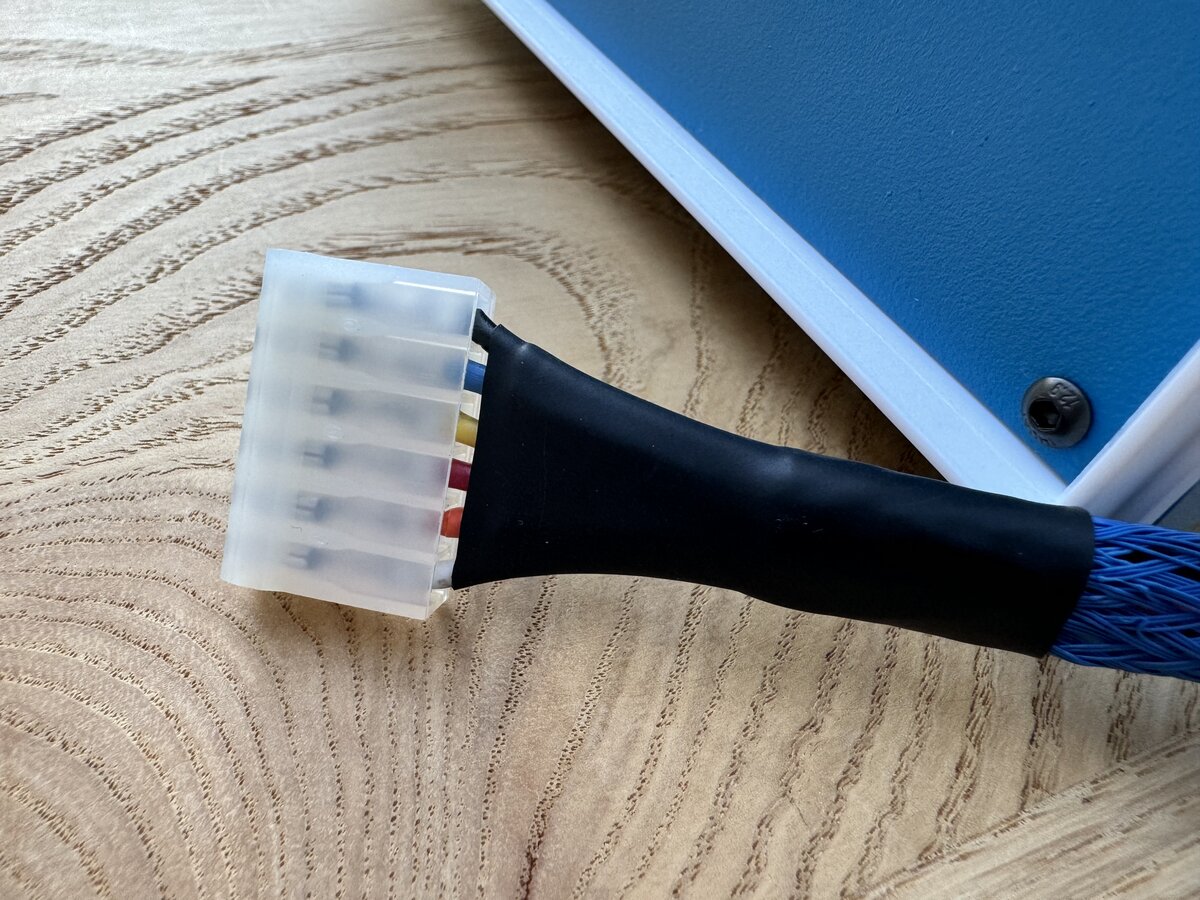
I started by updating my original cable. I removed the sleeve and the heat shrink tubing, and then I followed Uncle Bernie’s advice, and decided that I would keep only five out of the six wires. You can see the updated Molex side here.
Indeed, wires 5 and 6 are both “ground” and connected together on the PCB, so only one of those is needed on the cable. It seems that removing wire 5 (instead of wire 6) has the benefit that if you also remove pin 5 of the connector on the Apple-1 board, reversing the connector by mistake should not cause a short or blow up anything. However, I still have pin 5 on my board, so I better not reverse the connector in any case.1
I forgot to take pictures of the process, but I carefully placed heat shrink tubing on the wires, then the sleeve, and the plastic end of the DIN connector. You have to put the various parts in the right order or things won’t work out! I then soldered my 5 wires to the male DIN connector pins, in the same order that they are on the Apple-1 Molex connector. Soldering was the most difficult part, as my wires are 18 AWG (while 20 AWG would have worked as well), and the pins inside the connector are smaller. I did ok though, and I wrapped each solder joint with heat shrink tubing. I was then able to close everything, adjust the sleeve, and use the black shrink tubing to cover the other end, near the Molex connector, as I had done before.
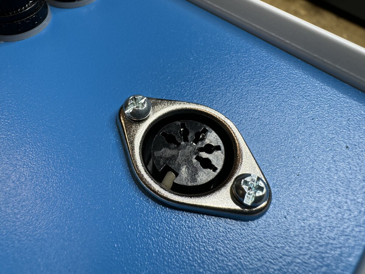
Then I soldered wires to the female connector. This was much easier and more secure than with my previous cheap connector. You can see how the metal pins nicely open outward, making it easy to solder larger wires to them.
Again, I added heat shrink tubing to protect all connections. I also soldered a wire to the chassis of the DIN connector to connect to the case’s ground.
NOTE: The Apple-1 “ground” does NOT connect to the metal case or to the mains’s ground wire. It is advised not to ground the Apple-1 this way, so it remains “floating” relative to the ground.
I reconnected the wires inside the case, and screwed the connector to the case.
Here is the entire back panel, without cables connected.
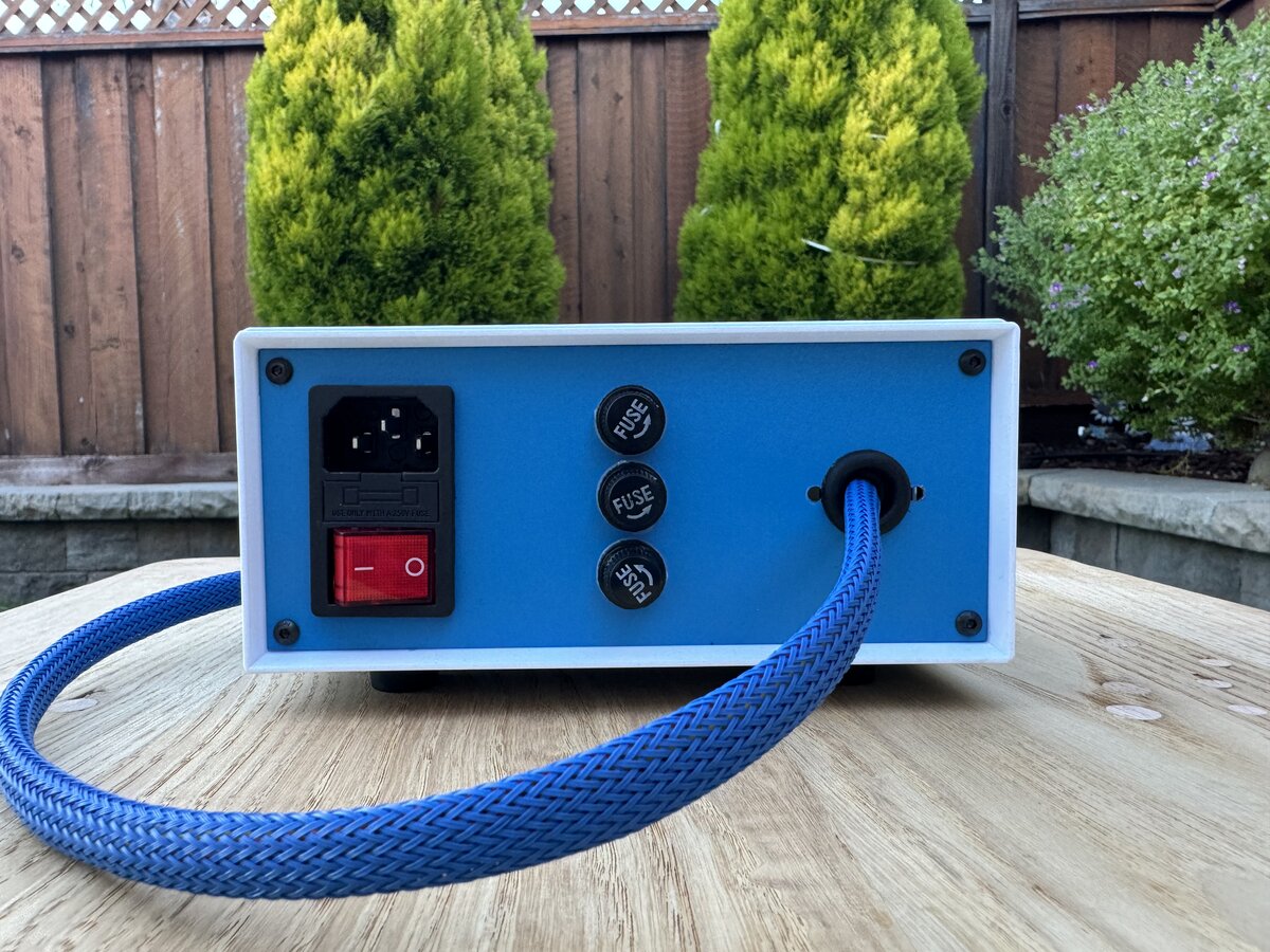
You can see here how the output cable connects to the power supply. It’s much neater than the previous version.
Time will tell if this DIN connector idea is robust enough. I think that using a PCIe 6-pin connector would be more robust, but I don’t think there are panel-mounted connectors, so this solution would require cutting a rectangular opening in the back panel and a supporting PCB that is secured to the back or bottom panel. In the end, this would be significantly more work. The pinout would still be non-standard, as this PCIe connector is normally meant to have 3 ground pins and 3 +12 V pins.
Credit: D-Kuru/Wikipedia
Small tasks
The specific power entry module I chose is meant to clip on a case panel. However, my panels are thin, and there was some clearance between the clips and the panel, making the module wobble. I considered using a spacer, but couldn’t find something of the right thickness. So I decided to use JB Weld epoxy instead: this sets really hard, with the drawback that ever removing the module will be difficult.
I also added some labels made with a label maker. This is not fancy, but it’s better than nothing. I might improve on this later.
Remaining work
Here are a few tasks that I’d like to complete:
Bleeder resistor: I have not installed a bleeder resistor in the power supply or on the cable. The idea is to help discharge the capacitors on the Apple 1 board when the power supply is turned off.
Grounding: It is generally a good idea to ground any metal part exposed to the user, in case a hot wire inside the case gets loose and contacts the metal. I have already grounded the bottom and top panel, but I still need to properly ground the front and back panels.
Logo or badge: I’d like to eventually put a copy of the vintage Apple logo2 on the front panel, maybe etched or engraved. Alternatively, I could use a simpler “Apple-1” badge and reserve the fancy logo for the main board.

The original Apple Computer Co. logo
Conclusion of part 2
I now have a pretty good-looking Apple-1 power supply. The result is definitely not period-correct, but it is hopefully “hacker-correct”. The Apple-1 was a hobbyist’s machine, so not only does it not matter if what you do is not exactly what would have been done in the 1970s, but it is, on the contrary, a good thing, provided you do it with care.
For more pictures, see:
Part 3 covers building the Retro Chip Tester Pro.
One certain problem is that the secondary of the 10 V transformer will short and (hopefully) cause the corresponding fuse to blow. ↩
Here is some background on this logo, created by Ronald Wayne, here. ↩
Comments powered by Disqus.