This is part 3 of a series of posts about building an Apple-1 reproduction in 2024. See also:
- Building an Apple-1 Reproduction in 2024 - Part 1: Components
- Building an Apple-1 Reproduction in 2024 - Part 2: Power Supply
- Building an Apple-1 Reproduction in 2024 - Part 4: Assembly
- Building an Apple-1 Reproduction in 2024 - Part 5: Monitor, Keyboard, Power-Up
- Building an Apple-1 Reproduction in 2024/2025 - Part 6: C Programming
- Building an Apple-1 Reproduction in 2024/2025 - Part 7: The Audio Cassette Adapter
Introduction
Right from the beginning of this project, one of my fears was that I would spend time and money, assemble things the best I could, and then turn on the power and face a non-working computer. One reason for this is that not all the components I bought were sold as tested. Remember, I didn’t buy a kit, but instead bought components from various sources. The DRAM, 2504s, and 2513 were sold to me by Arunas in Lithuania as tested, but while the expectation was that the chips I bought from other places were in working condition, they were not specifically tested by sellers, including the components bought from Unicorn Electronics, Anchor Electronics, or other eBay sources.
Finding which out of the 61 integrated circuits of the Apple-1 might not be working could lead to some very painful troubleshooting sessions. So I considered what I could do to reduce that risk.
Testing components
For my TVI-912 repair, I wrote my own basic memory tester with an RP2040, and it worked! But here we are talking about testing many chips of different types. Unless I wanted to embark into the completely different project of making my own general-purpose tester, I needed to use something off the shelf. I decided to build a Retro Chip Tester after reading about it and watching videos reviews.
The Retro Chip Tester Pro (or RTC) is a project by Stephan Slabihoud in Germany. Stephan runs a website dedicated to retro computing. You typically buy the PCB, optionally with the microcontroller already programmed and soldered, but you have to buy the rest of the components yourself, although I think that some third-parties sell fully-assembled RTCs.
While this is not an open source project, there is above-average documentation for building and using the device, and there is an official support forum on Reddit.
The RTC can test a wide range of older chips, including the 74xx series, 4000 series, SRAM, DRAM, and more. Here is the list of Apple-1 chips and whether they can be tested with the Retro Chip Tester Pro:
| Chip | Quantity | RTC | Comment |
|---|---|---|---|
| 7400 | 3 | Yes | |
| 7402 | 1 | Yes | |
| 7404 | 1 | Yes | |
| 7408 | 1 | Yes | |
| 7410 | 2 | Yes | |
| 7427 | 1 | Yes | |
| 7432 | 1 | Yes | |
| 7450 | 1 | Yes | |
| 74123 | 1 | Yes | |
| 74154 | 1 | Yes | |
| 74157A | 2 | Yes | |
| 74160 | 1 | Yes | |
| 74161 | 5 | Yes | |
| 74166 | 1 | Yes | |
| 74174A | 1 | Yes | |
| 74175A | 1 | Yes | |
| 74S257 | 4 | Yes | |
| 8T97 | 2 | Yes | |
| 6502A | 1 | No | CPU |
| 6520A | 1 | No | PIA |
| 2504 | 7 | No | shift-registers |
| 2513 | 1 | Adapter | with -5V/-12V, use 2704 settings with adapter |
| 2519 | 1 | No | shift-register |
| DS0025CN | 1 | No | clock chip |
| MK4027N-4 | 16 | Yes | use 2104 DRAM setting |
| 27C64 | 1 | Yes | EPROM replacement |
| 74LS02 | 1 | Yes | ACI |
| 74LS10 | 1 | Yes | ACI |
| 74LS74 | 1 | Yes | ACI |
As you can see, there is quite good coverage.
Ordering the parts
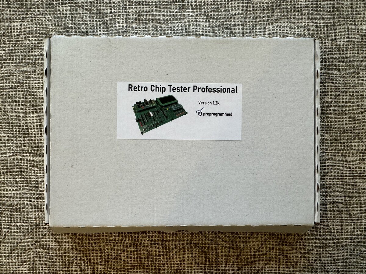
I got in touch with Stephan about ordering. I paid EUR 108 (about USD 118) total for the main PCB and the DC-DC module (EUR 68), the soldered and programmed microcontroller (EUR 12), and shipping (EUR 28). Transit of the package to the US took weeks, but I was not in a hurry. The items arrived safely. They came in a nice box.
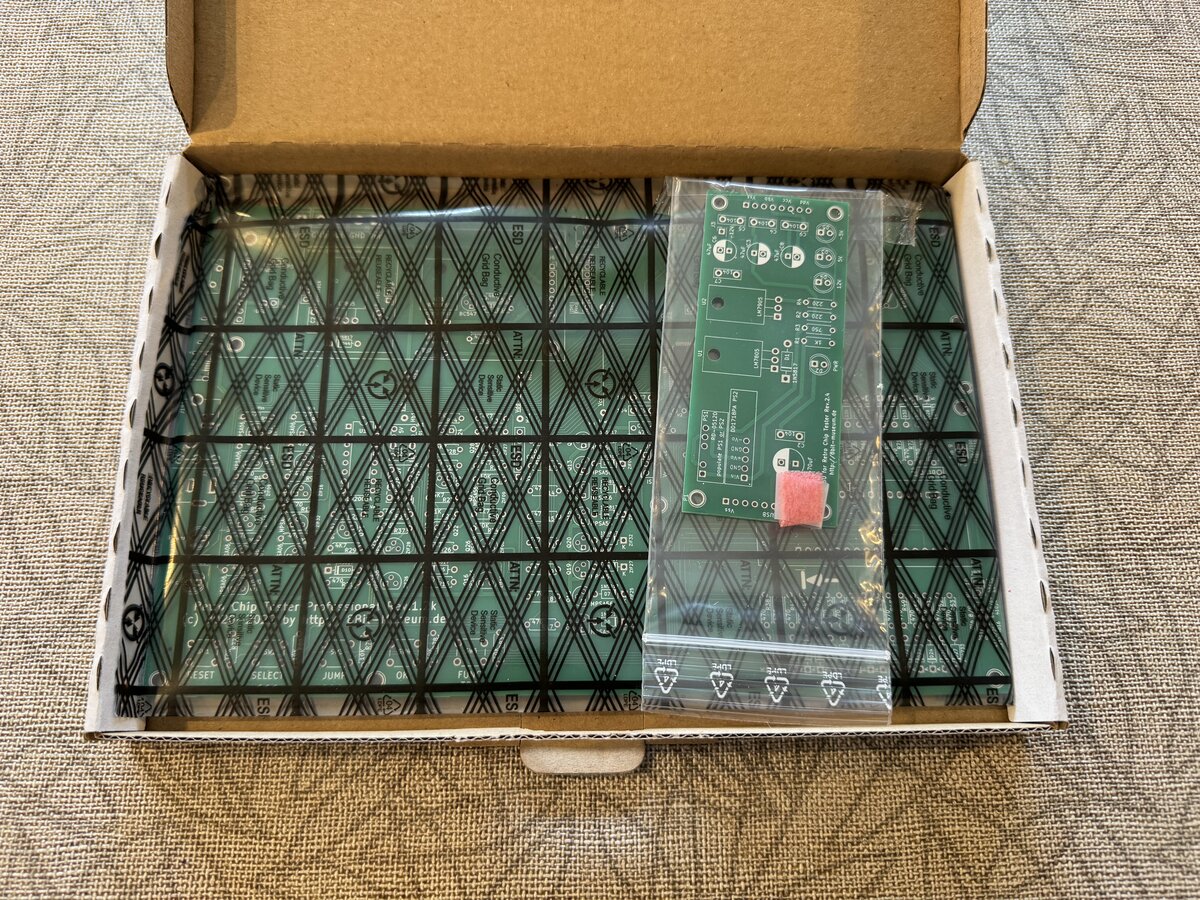
The PCBs are nicely packed inside:
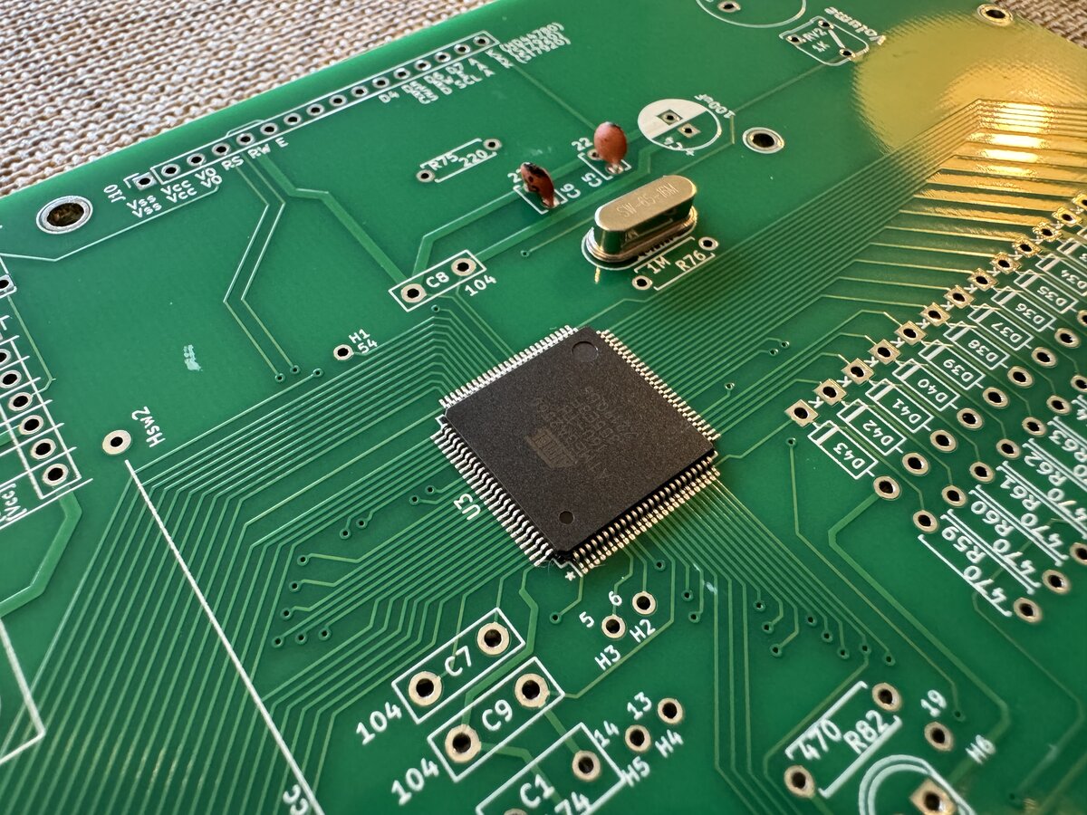
Here is why I bought the soldered and programmed microcontroller: I am not confident that I could solder something that small.
In the meanwhile, I looked at procuring the rest of the components for the board. There are PDF files detailing the BOM, options for some of the parts, what to watch for, etc. I started with a pre-configured DigiKey cart, and double-checked it and added to it.
In addition to items that you can get from online electronics stores like DigiKey, there are a few components you need to get separately:
- nylon standoff screws
- LCD display
I got these from AliExpress. You have a choice for the LCD, as it is a standard two-line display, and you could even get an OLED version, but for a large premium. I went with a yellow LCD, which, I thought, looked cool.
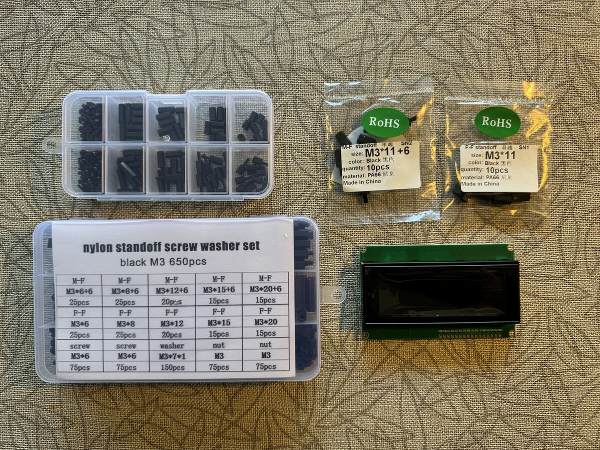
I had ordered the extra power module board, which I might not really need immediately. It provides regulated 5 V, -5 V, and 12 V (but no -12 V).
Here is my total cost for the RTC:
| Item | Cost (USD) | Details |
|---|---|---|
| PCBs, MCU, and flashing | $118.00 | Directly from Stephan |
| Other components (including DC-DC board) | $122.56 | DigiKey |
| LCD and spacers | $26.61 | AliExpress |
| Extra diodes | $6.55 | Amazon |
| Total | $273.72 |
Building the RTC
One thing that Stephan recommends is to test the Zener diodes. I made a simple test setup using my regulated power supply (not shown here, and neither is the multimeter).
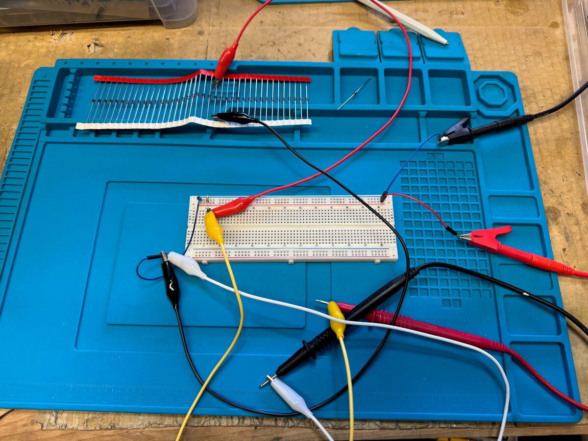
Unfortunately, the values were all a little off compared to what the instructions recommend. I asked Stephan about it and he said it should be fine, but still pointed to a set of Zeners that work for him. I ordered those from Amazon, and they were spot on. So I used the new Zeners.
I followed the build instructions and I soldered the low-profile components first, including the Zeners and resistors.
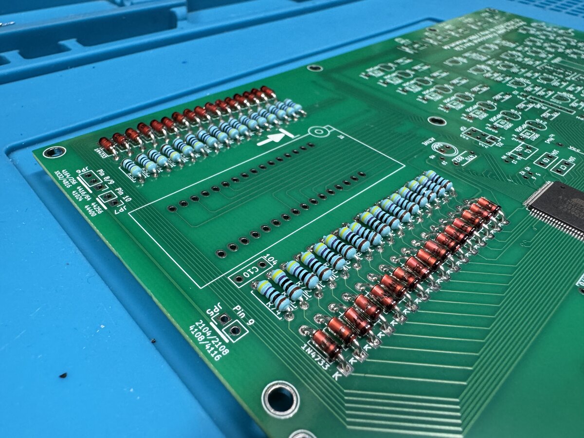
You then solder the IC socket, transistors, relays, and the rest of the components. Soldering by height is just a matter of convenience: it just makes it easier to solder.
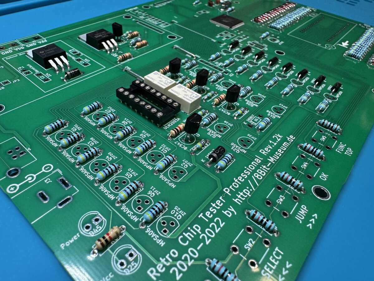
I then soldered the power module, put the LCD headers in place, the spacers, and I was done!
I built a somewhat maximalist build, with the power module, and all the ways to power the board: barrel connector, USB-B, micro-USB, and screw terminals.
Using the RTC
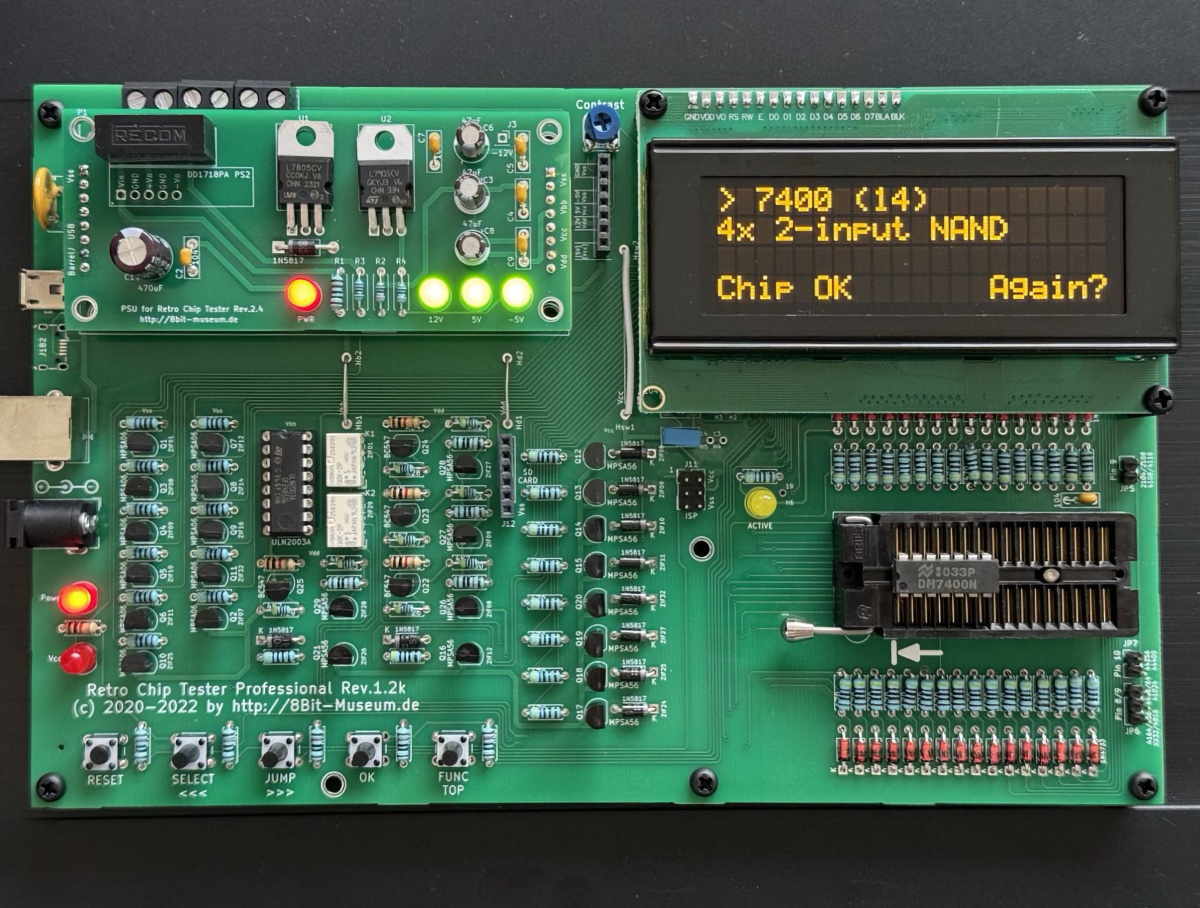
I plugged the RTC for the first time, plugged a chip in, and it worked right away! Here I am testing a 7400 chip.
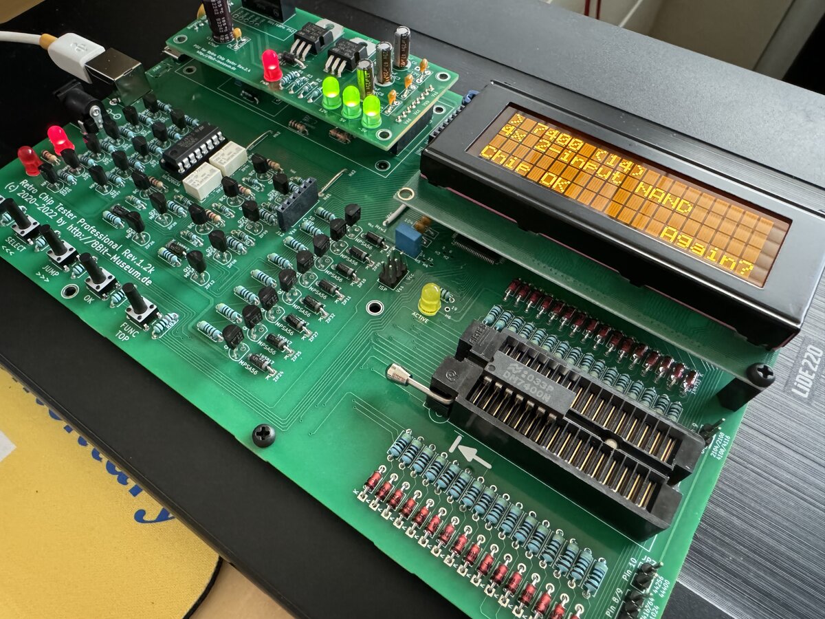
The UI is pretty easy to use. You have to use the switches to navigate the menu. The only issue is navigating in large series of chips, like the 74xx series. You can hold the button and it will start jumping by 10s, which helps. It’s not a big problem, and you get used to it.
I like that there is a buzzer indicating success or failure. It’s a nice touch. You can also very easily test the next chip in a batch: remove the chip, put the next one, and press the button.
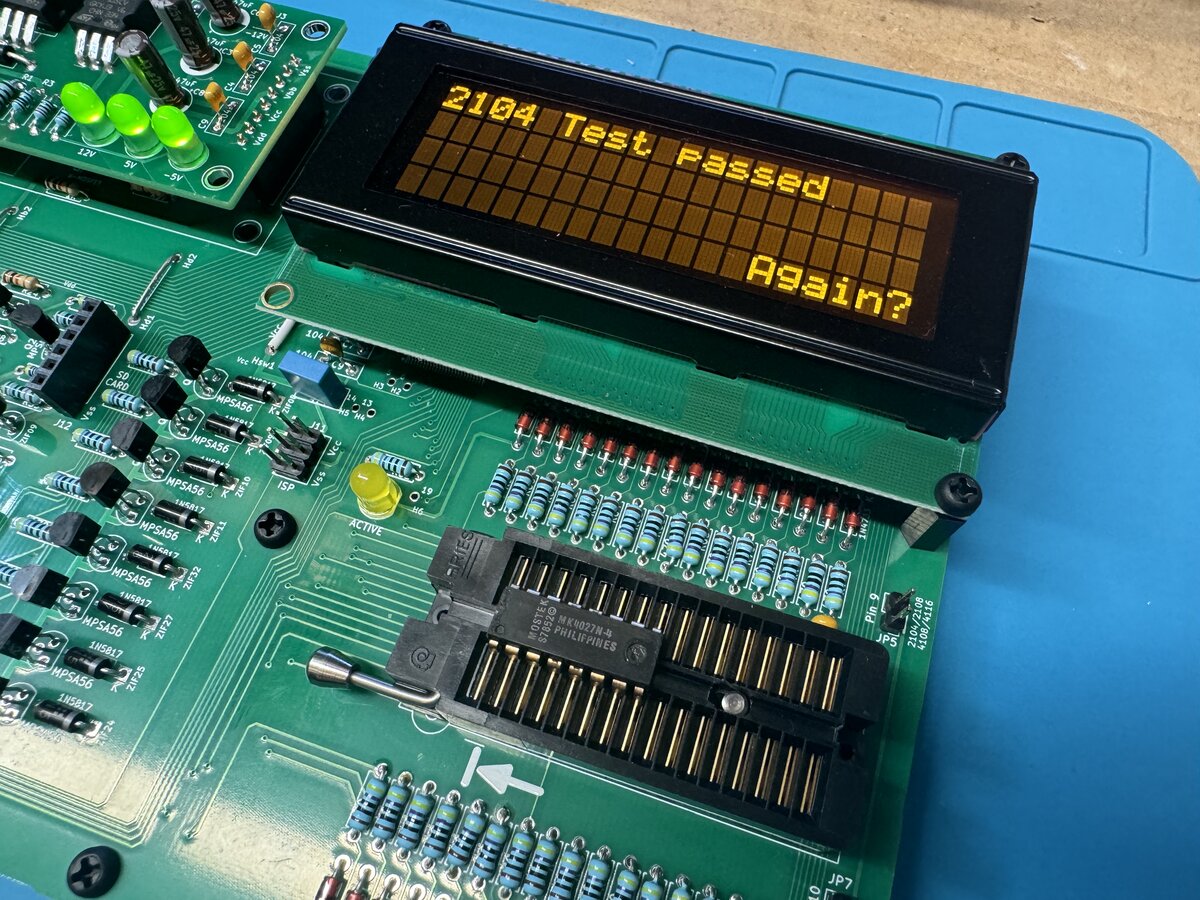
I was able to test the chips, listed above, that I had bought for the Apple-1, and they all passed, including the Mostek MK4027N-4 DRAMs.
Since my original orders of components for the Apple-1, I stumbled onto two fairly large sets of 74xx series chips.
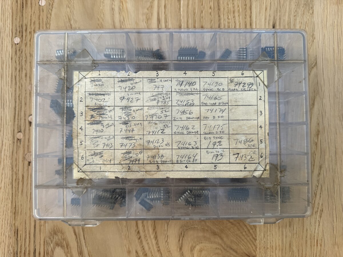
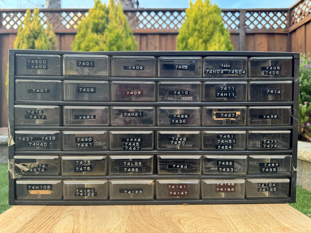
So of course I started testing those chips. As of October 2024, I am not entirely done, but only a small subset so far showed as failing. I only encountered an issue so far with two types of chips:
- 7441 (9 instances)
- 7473 (57 instances)
The tester reports that they all fail, which seems unlikely. I wonder if it is the chips, the tester, or the algorithm used to test them.
UPDATE: Stephan indicates that these chips must be positioned specially in the ZIF socket. In fact, the display shows that (“Pos 4” or “Pos 5”). So it was a user error, not having RTFM. By positioning the chips correctly, most of these chips now test fine!
Conclusion
Although it wasn’t exactly cheap, I am glad I built the RTC. It gave me more confidence about completing the assembly of the Apple-1 reproduction, and hopefully will also be useful for other projects.
Part 4 covers the assembly of the Apple-1.

Comments powered by Disqus.