This is part 4 of a series of posts about building an Apple-1 reproduction in 2024. See also:
- Building an Apple-1 Reproduction in 2024 - Part 1: Components
- Building an Apple-1 Reproduction in 2024 - Part 2: Power Supply
- Building an Apple-1 Reproduction in 2024 - Part 3: The Retro Chip Tester
- Building an Apple-1 Reproduction in 2024 - Part 5: Monitor, Keyboard, Power-Up
- Building an Apple-1 Reproduction in 2024/2025 - Part 6: C Programming
- Building an Apple-1 Reproduction in 2024/2025 - Part 7: The Audio Cassette Adapter
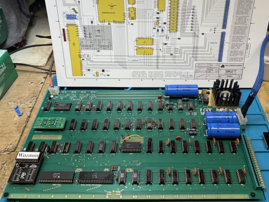
Assembly
Assembling the board is the meat of the project. To get prepared, I read some material: I obtained, in particular, “UNCLE BERNIE’S TIPS AND TRICKS FOR APPLE-1 BUILDERS Version: V3.01 - Turned loose on the world on 12th March 2023”, which he kindly sent me. This is an invaluable resource.
I had also watched some videos on YouTube over time: there are a few covering the building of Apple-1 reproductions from kits, including:
- The 8-Bit Guy: How the Apple 1 computer works
- Retro Hack Shack
I started by quickly inspecting the PCB. It was supposed to be electrically tested by the PCB manufacturer, but I still wanted to make sure that there were no obvious issues, and I didn’t see any.
The first components I soldered were the resistors. I had measured all of them to see how close their values were to the nominal value, and all the Allen Bradley resistors I measured were a little high, but not by too much, usually within 10-15%.
I wanted them to look good on the board, so I did the following:
- carefully bent the leads
- cleaned the old leads with contact cleaner
- used flux to help the solder flow
- used a spacer between the resistor and the board (following a tip I saw in a video)
- soldered the top first, then the bottom
- used a wet sponge when soldering the bottom, to avoid overheating the resistor
- re-measured the resistors after soldering; they tended to measure even higher, as had been indicated by others
- cleaned the flux residue with isopropyl alcohol (IPA)
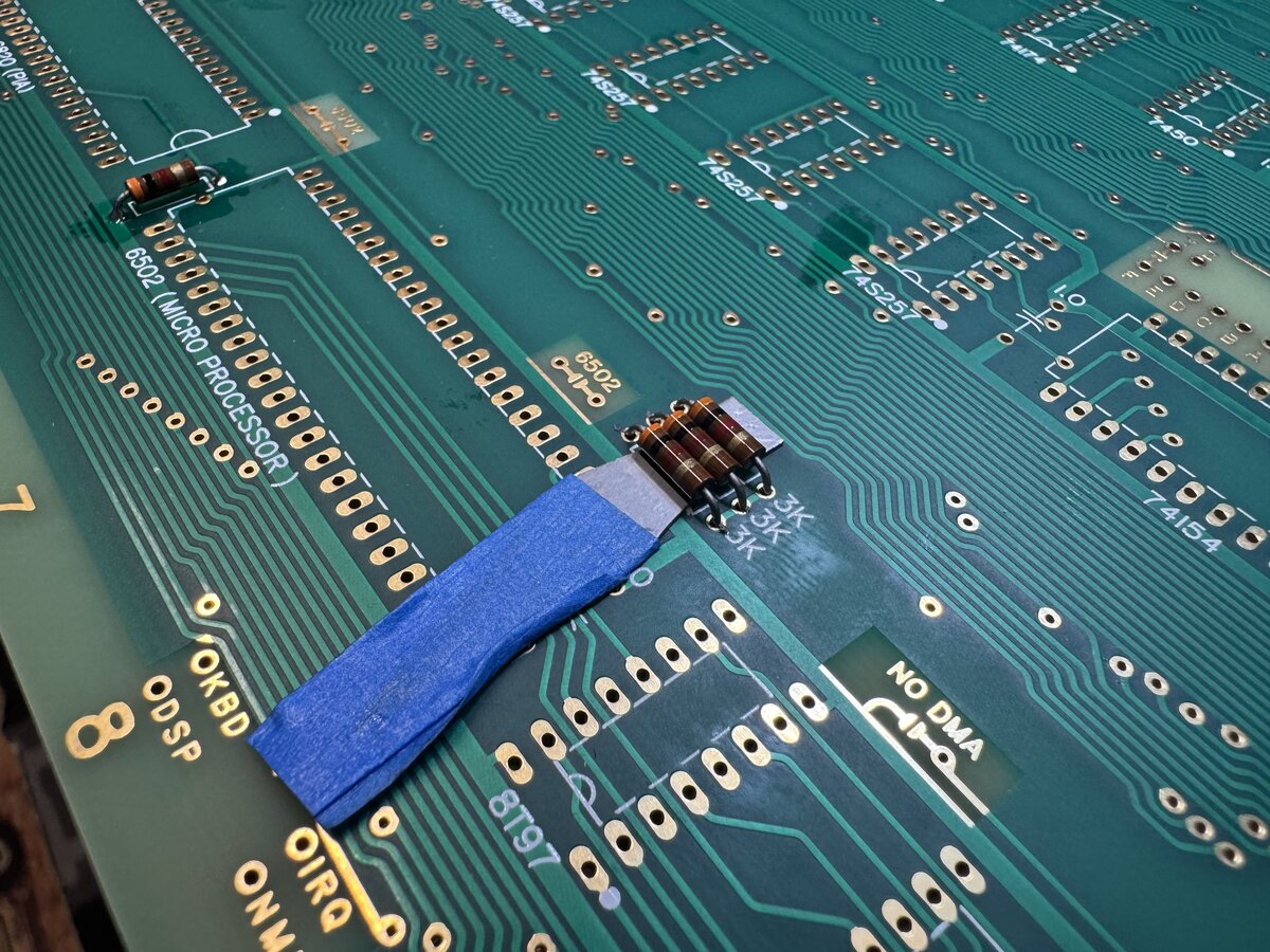
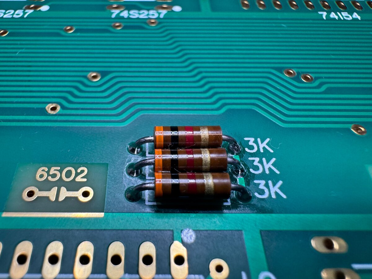
One recommendation is to make sure that the resistors in the C/D section are not more than 10% off. Also, for the 27 KΩ resistor, the advice is to use 22 KΩ instead. I used a modern resistor, but I plan to replace it with a vintage one.
My 7.5 KΩ resistors were measuring around 8 to 8.2 KΩ, which is fine. I decided to replace them with 7.5 KΩ resistors. I also replaced the 27 KΩ resistor with a 22 KΩ one.
Then I soldered the diodes. For the small signal diodes, there was no problem. But the big rectifier sinterglass diodes in particular caused me some trouble. First, my board is ENIG, so has a golden look. Solder is, of course, silver color. And here, the holes for the diodes are large, and the pads are huge. Soldering them made ugly blobs. I decided to tin all the large pads around the diodes. I reflowed a lot of solder, and I was worried about the heat for the diodes as well as the PCB. But it eventually worked ok and nothing was damaged that I could tell. I tested the diodes after soldering.
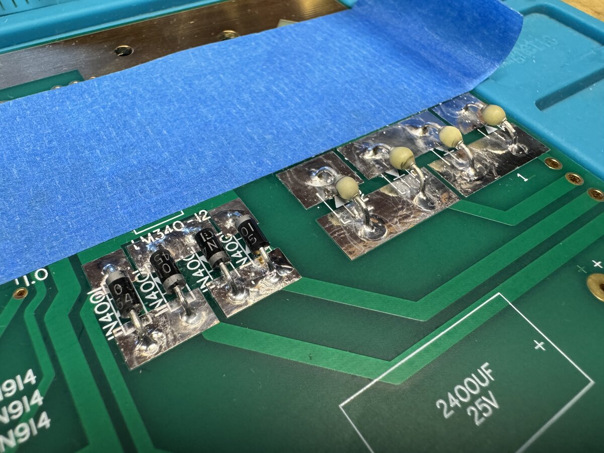
Here is the board with most of the resistors and diodes soldered:
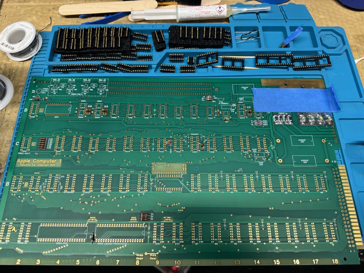
In-socket reliability mods
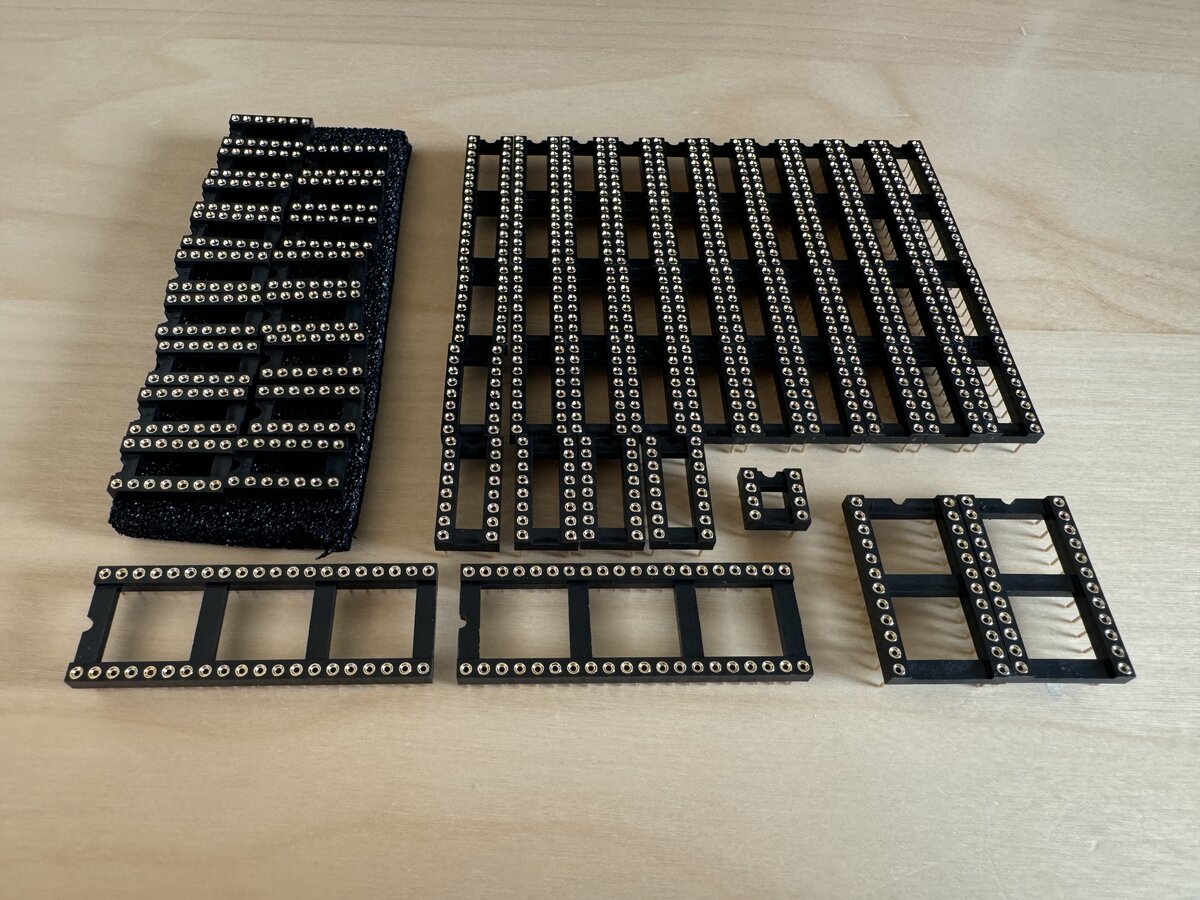
Then it was time to solder the IC sockets.
It is well-known that the Apple-1 had some design flaws, not in principle, but in some aspects of the layout of the PCB like power distribution, including lack of enough decoupling capacitors, the termination of some lines. The good news is that there are some easy fixes that objectively improve the reliability of the board. Uncle Bernie has pushed this to the next level, and I am following his advice to include his “reliability mods”: specifically, extra decoupling capacitors and termination resistors are added.
There are two main options to do this:
- solder those extra components at the bottom of the board
- hide them inside the IC sockets
I wasn’t sure I would do the latter, but I experimented with one socket and convinced myself that it was the way to go. It’s more work, but it’s so much cleaner. I used small pliers, flux, and patience. I observed the result under a magnifying glass to make sure that all connections were good.
For these, I used small, modern axial capacitors.
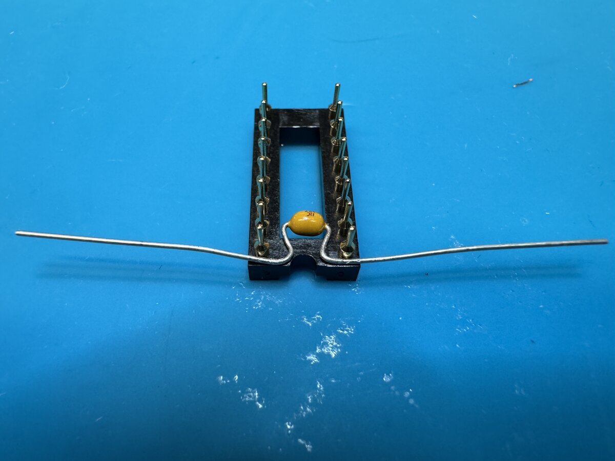
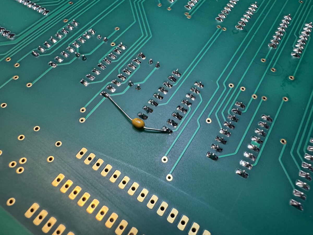
Several chips required the classic diagonal decoupling capacitor.
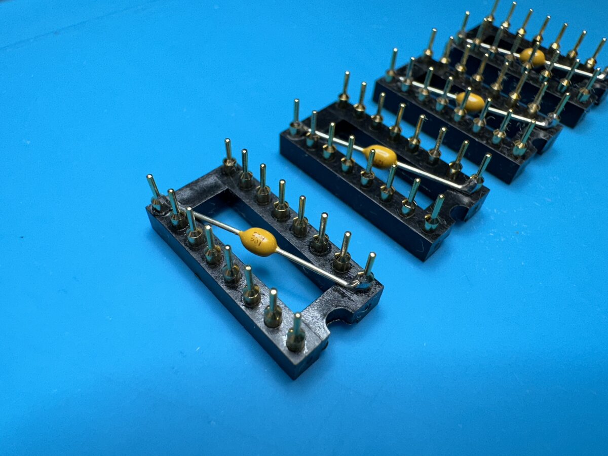
Here is the decoupling capacitor for the 6502:
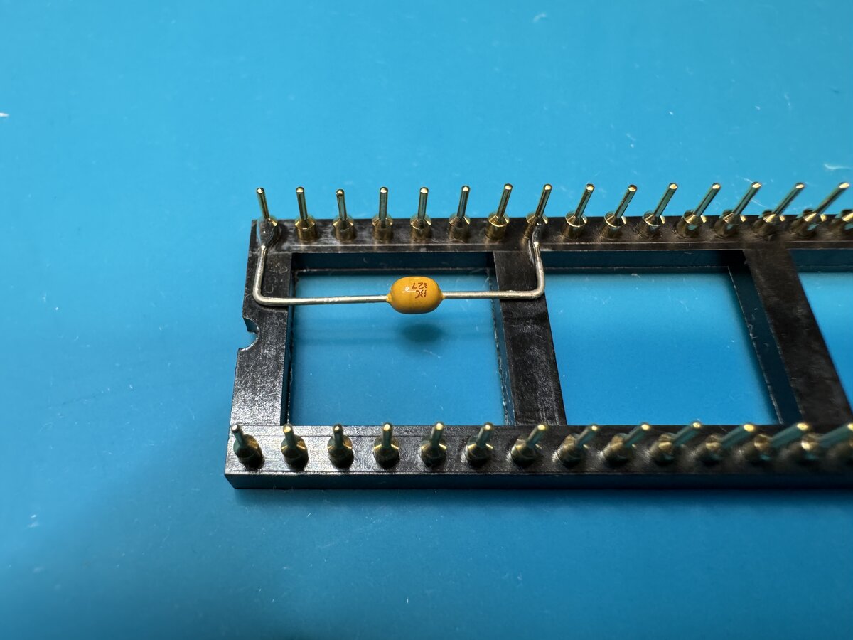
Some were more custom:
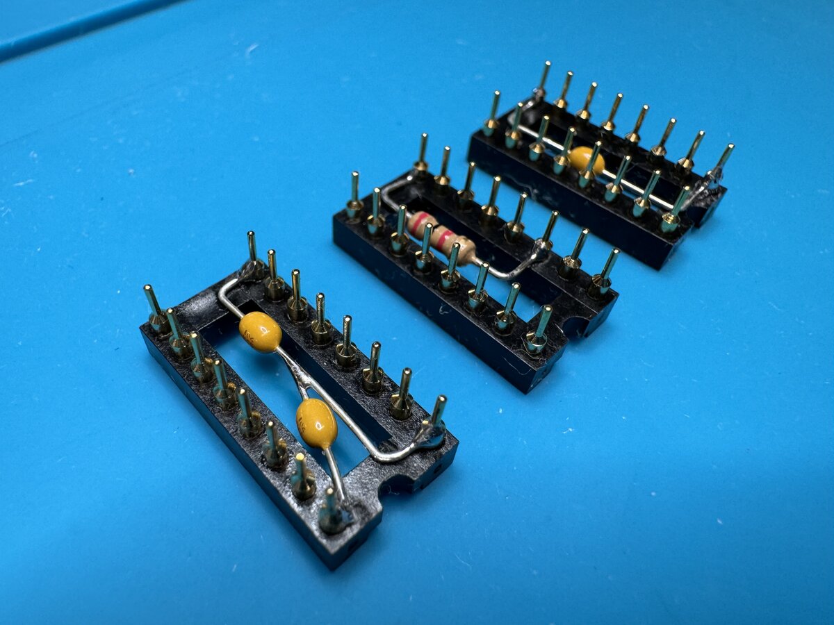
From the top:
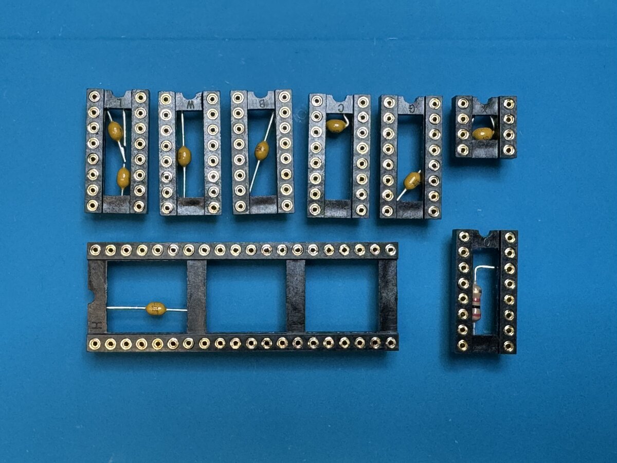
Here is the board with all IC sockets soldered:
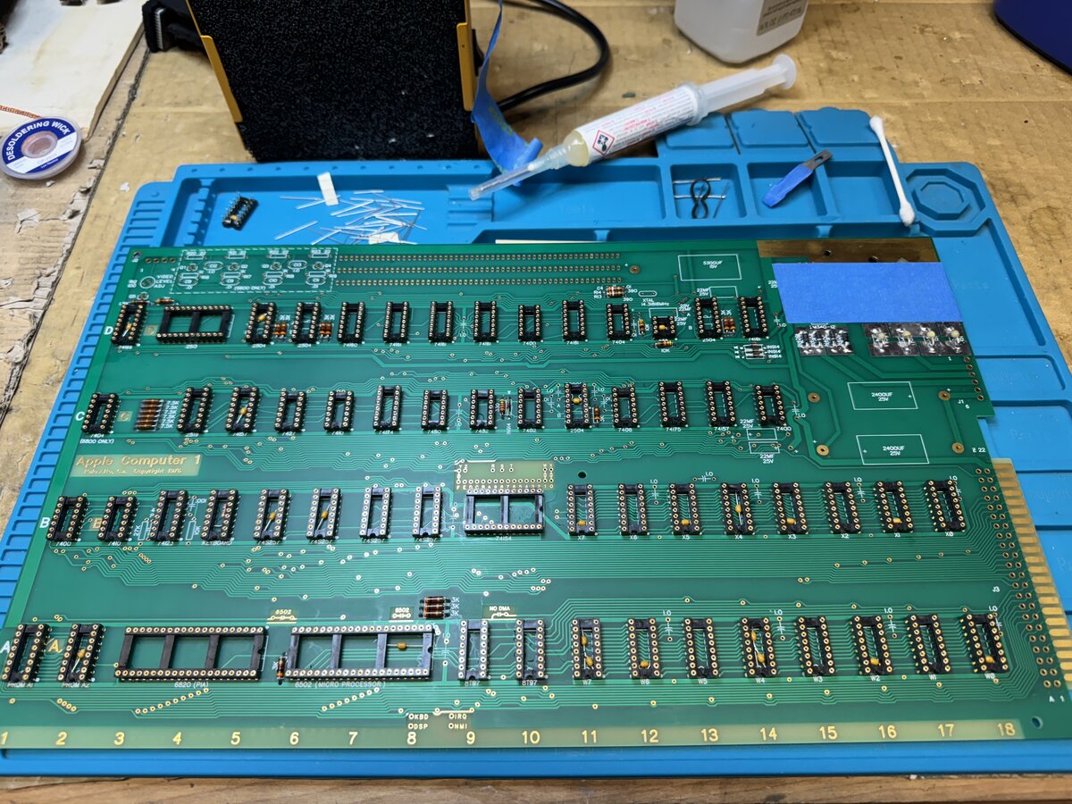
Fixing a problem
I thought that I wouldn’t be able to install the 6 termination resistors inside IC sockets, so I soldered the relevant sockets. But then, I was told that you could put 3 resistors in two separate sockets. What should I do, then? Solder them under the board? Install the resistors in a riser card? But then, what if the card is removed?
So I considered desoldering the already-installed sockets. I don’t have a proper, professional desoldering iron, but I found a tip on YouTube which consists in using a thick piece of copper wire to transmit the heat. I decided to try that. I was ok destroying the IC sockets in the process, but I didn’t want to damage the PCB. So I tried first on a random board I had, and it worked. Then I tried on my spare Apple-1 PCB as well. The only drawback is that the copper pads on top of the board got some solder in the process and have become gray. There is probably no way to get them golden again. But I was ok with that, as the pads are mostly hidden by the IC sockets. If you look you can see it, but it’s not too bad. So I decided to proceed.
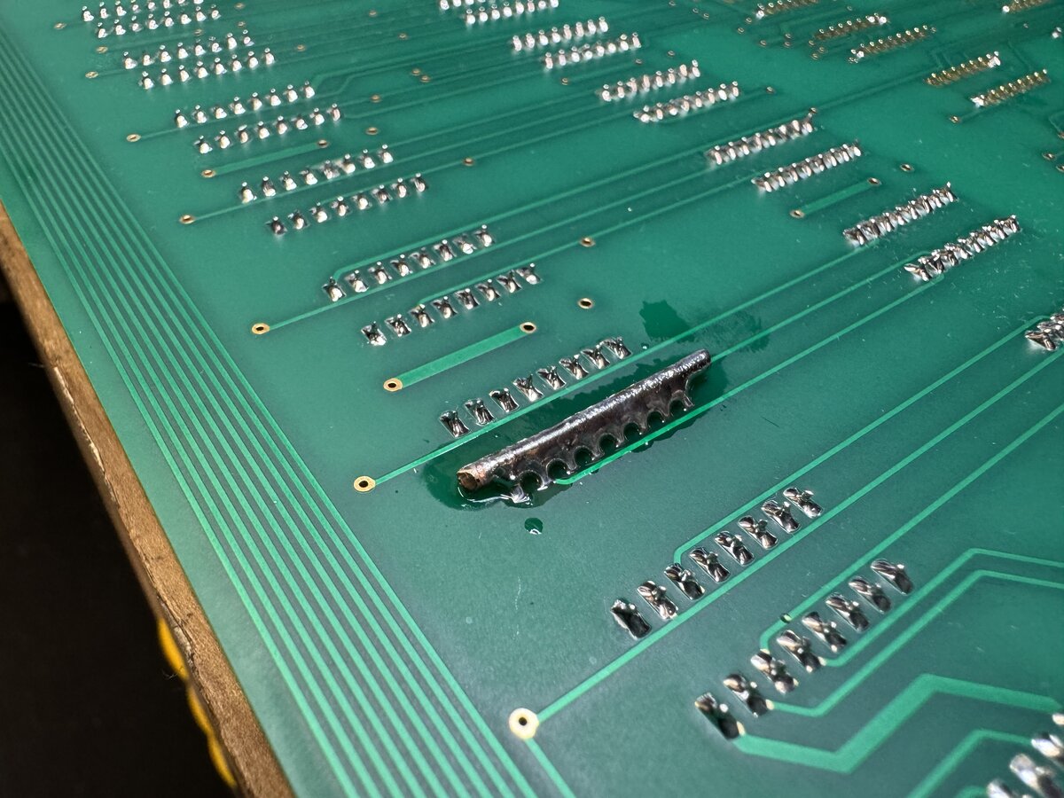
I used a lot of flux in the process.
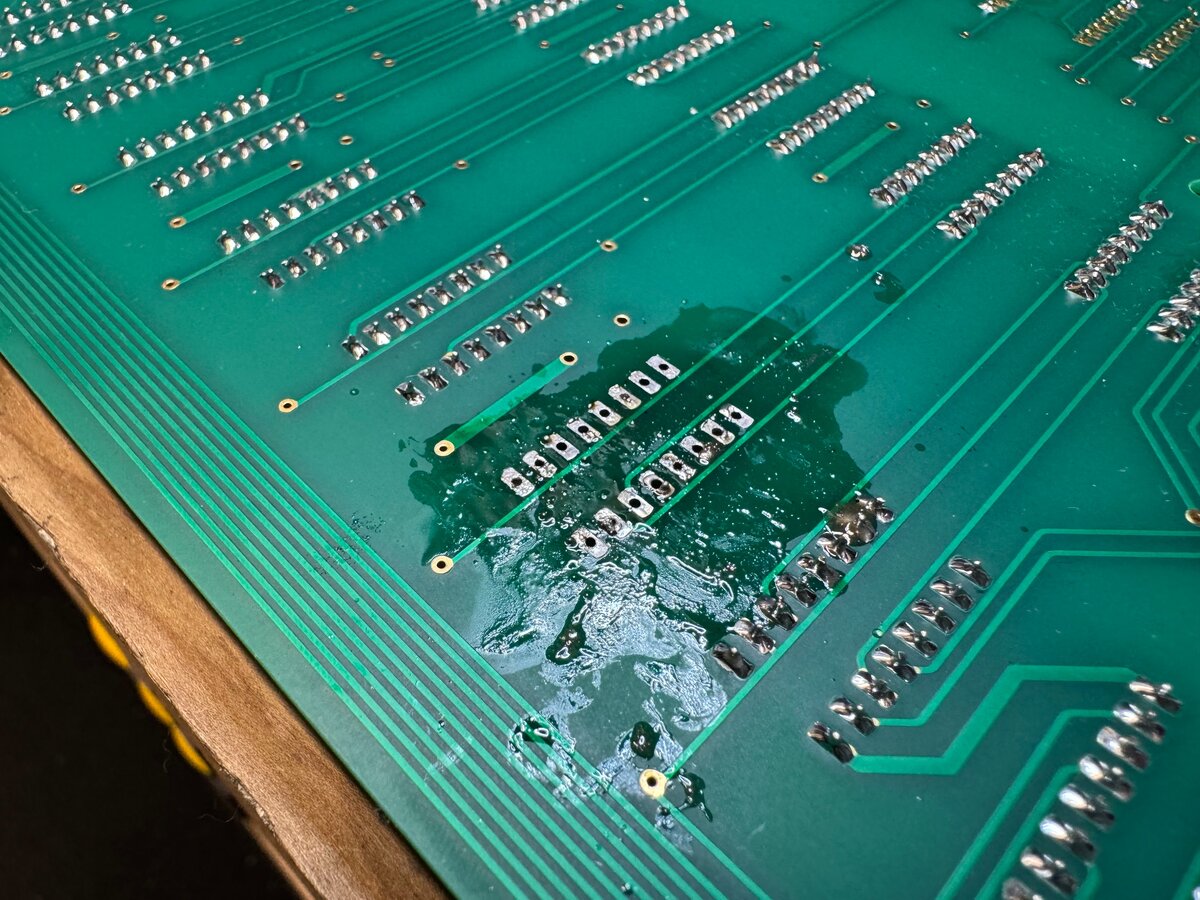
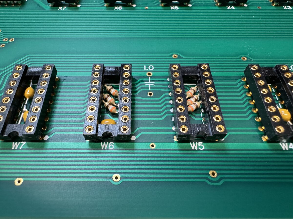
You can see the grayed pads here.
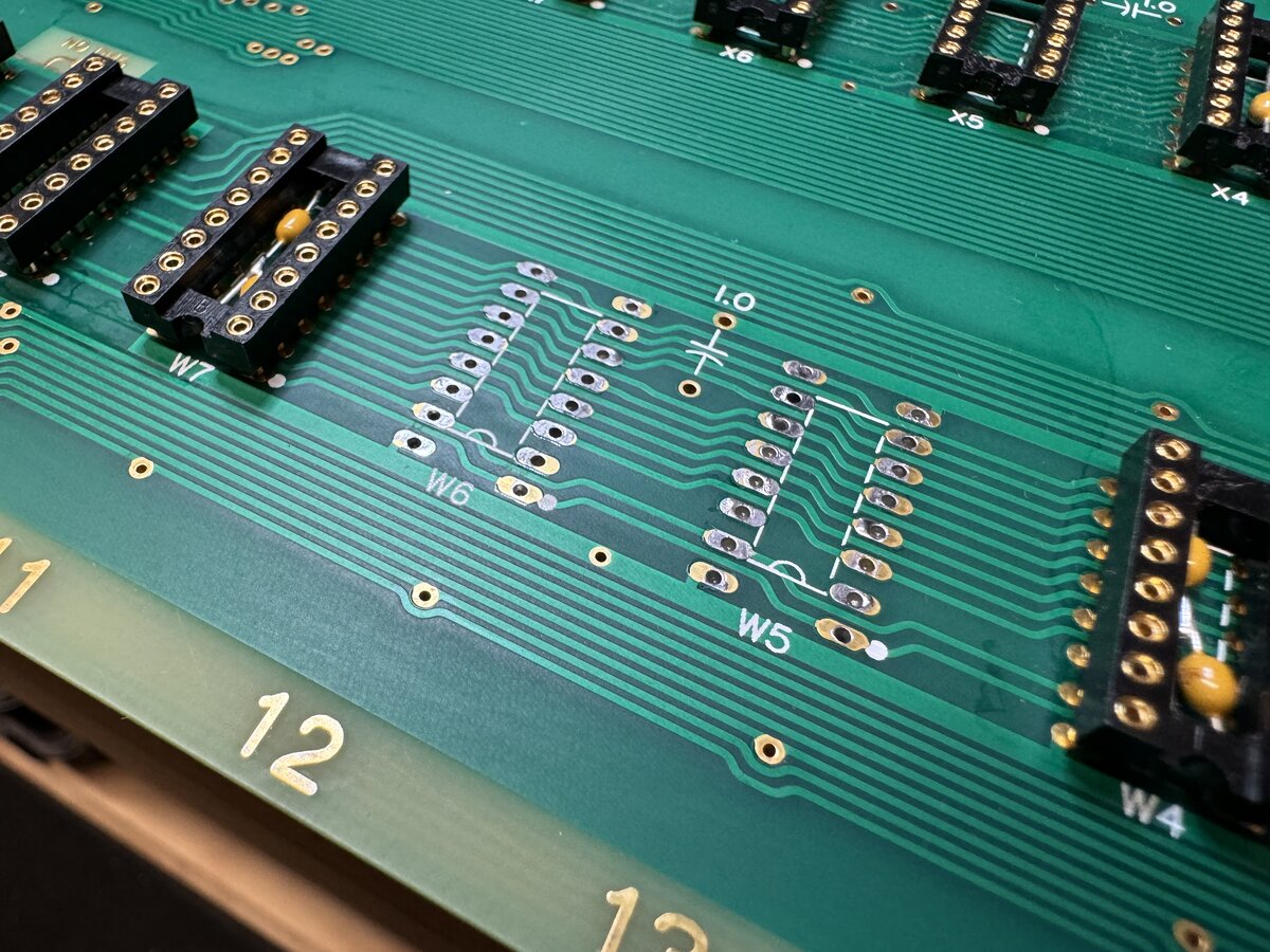
Here is one of the sockets with the resistors installed.
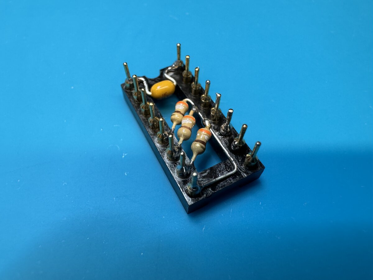
The final result.
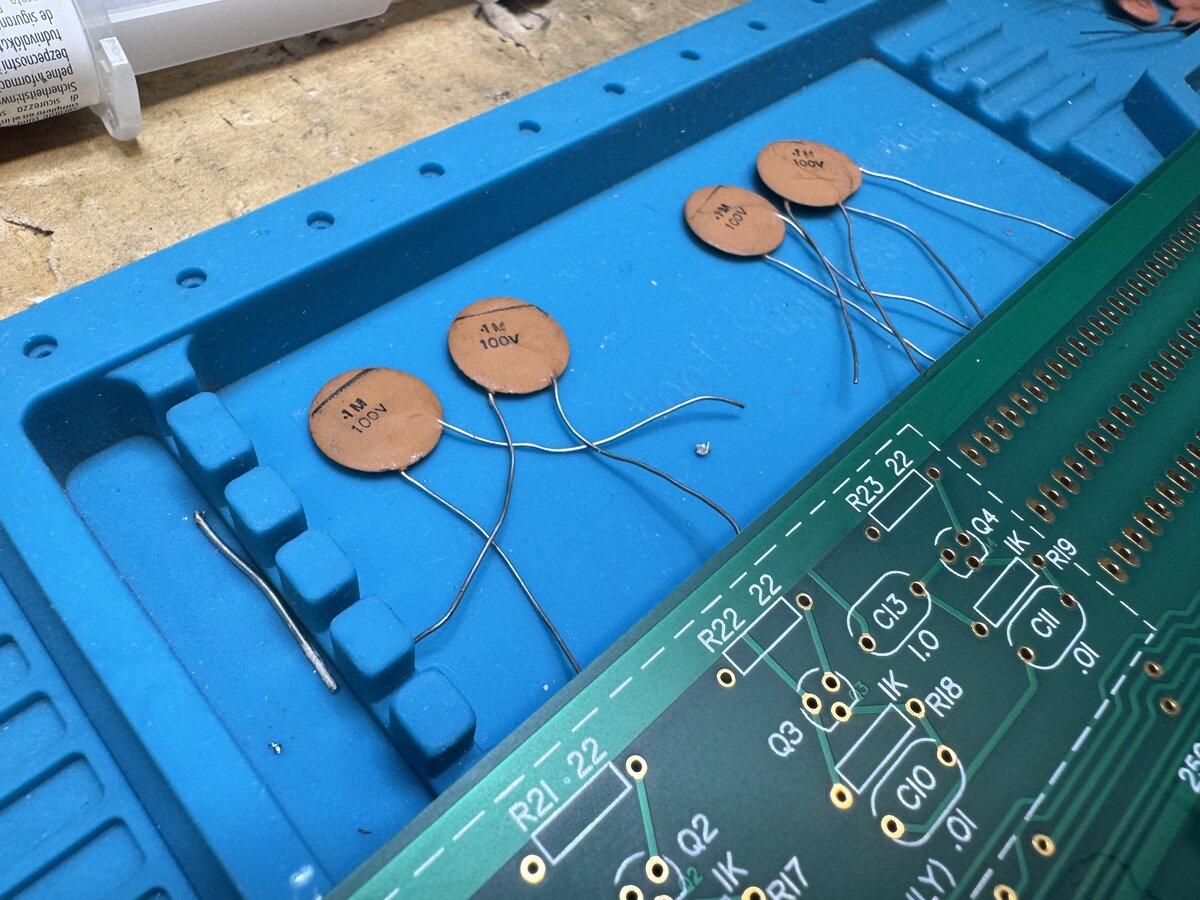
Decoupling capacitors
For these, I had bought old ceramic disc capacitors. These are weird beasts. They came in various sizes. I measured all of them, and unfortunately several were as much as 20% under spec. For decoupling capacitors, it’s ok to be higher, but not lower, especially given the above-mentioned issues with the Apple-1 not having enough decoupling capacitors. So I decided to use the ones that were close to spec.
I decided to make things look as good as possible, by using capacitors of similar size in each section. I managed to insert some capacitors with the leads going in diagonally, but for most capacitors I had to bend the leads to make them fit. Here are the capacitors in the memory section.
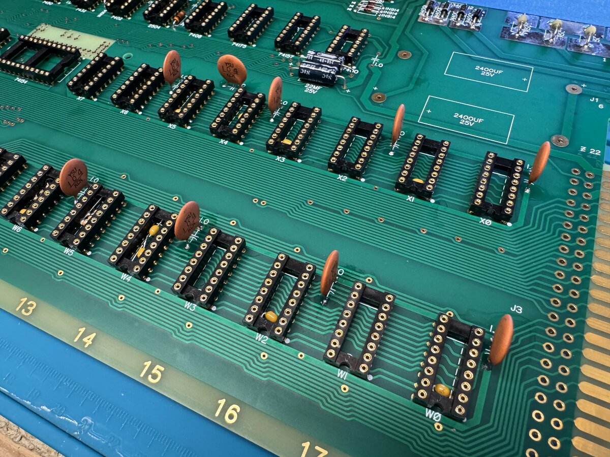
You have to be careful with these old ceramic capacitors: when bending a lead, I broke some of the outside packaging of one of them. Also, it is very easy to just bend them back and forth once installed, just as a matter of course when handling the board or soldering further components, as the leads are very thin. This might, eventually, cause some leads to break.
Other components
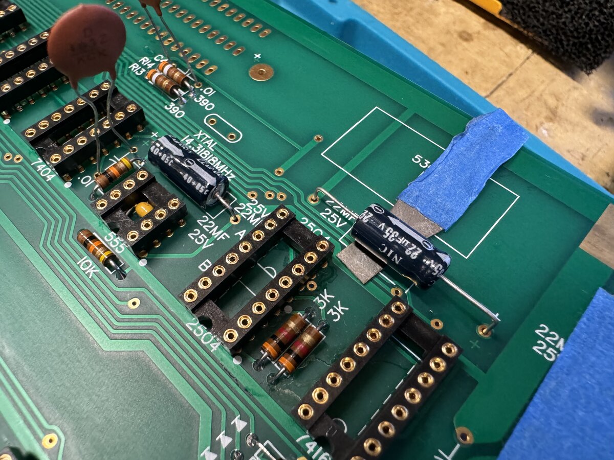
I also installed the remaining small capacitors. I carefully bent the leads, and also used a spacer.
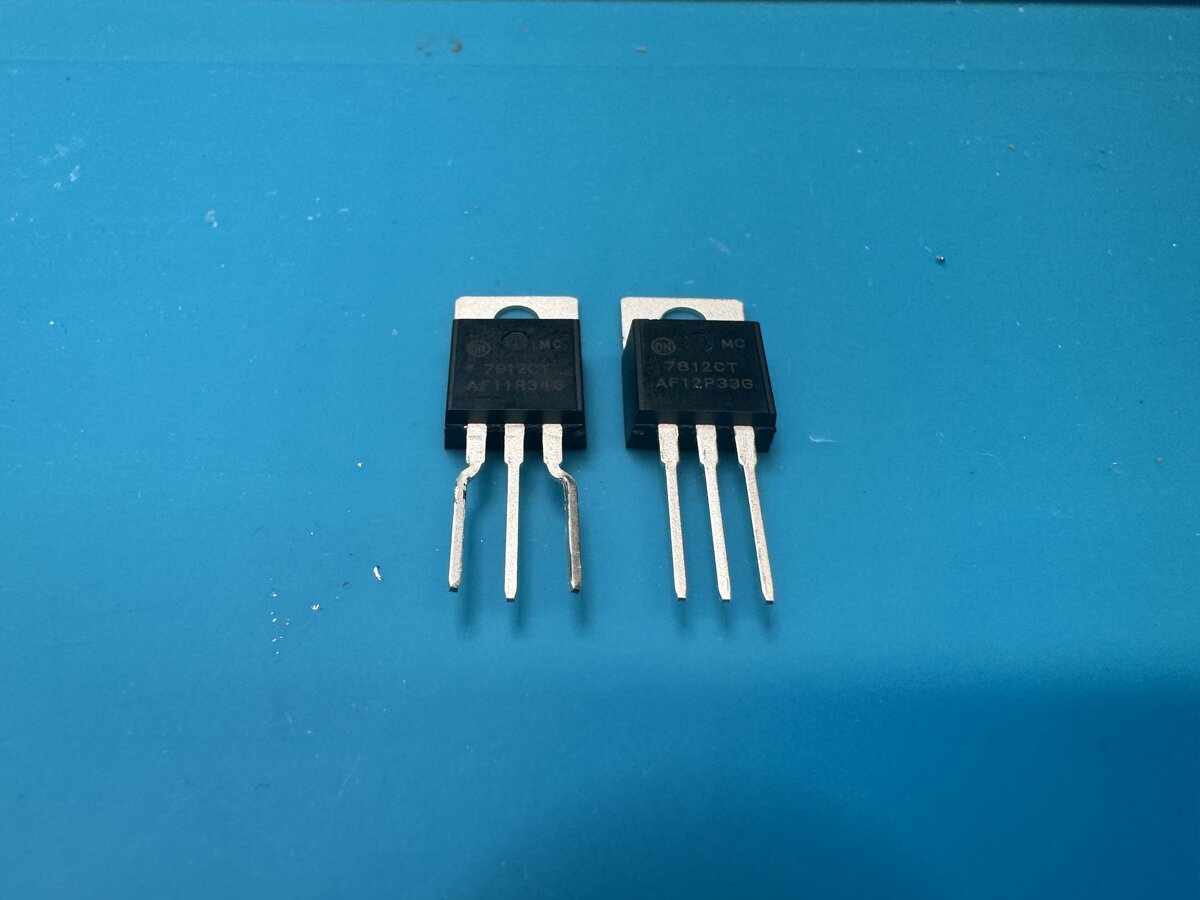
I then installed the smaller regulators. The pins needed to be bent with pliers to fit the holes.
I also installed the transistor and the video connector. Note the orientation of the connector: the vertical plastic part should go toward the outside of the board. The same applies for the similar 6-pin Molex connector for the power supply (I had initially wired my power cable exactly the wrong way and had to fix it).
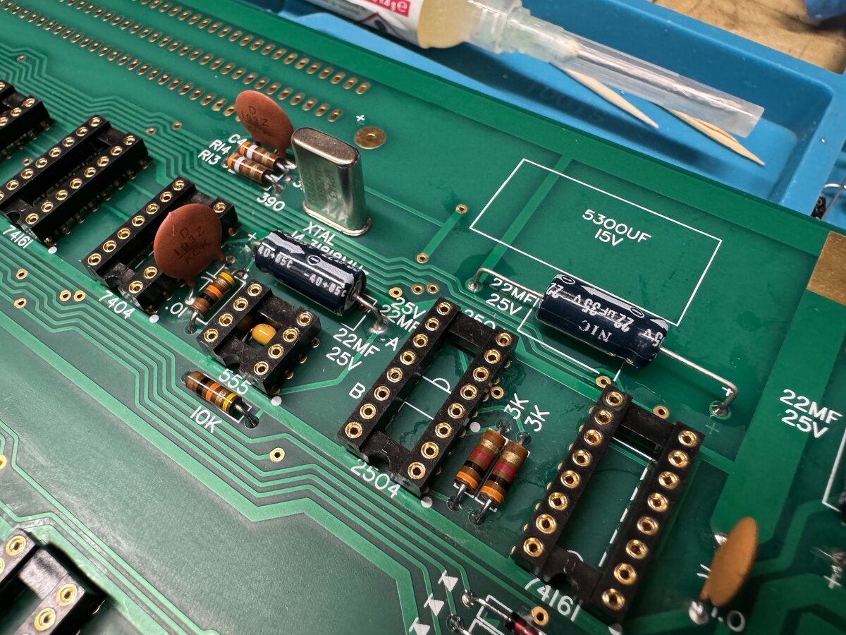
Here is a section with resistors, IC sockets, capacitors, and the quartz installed.
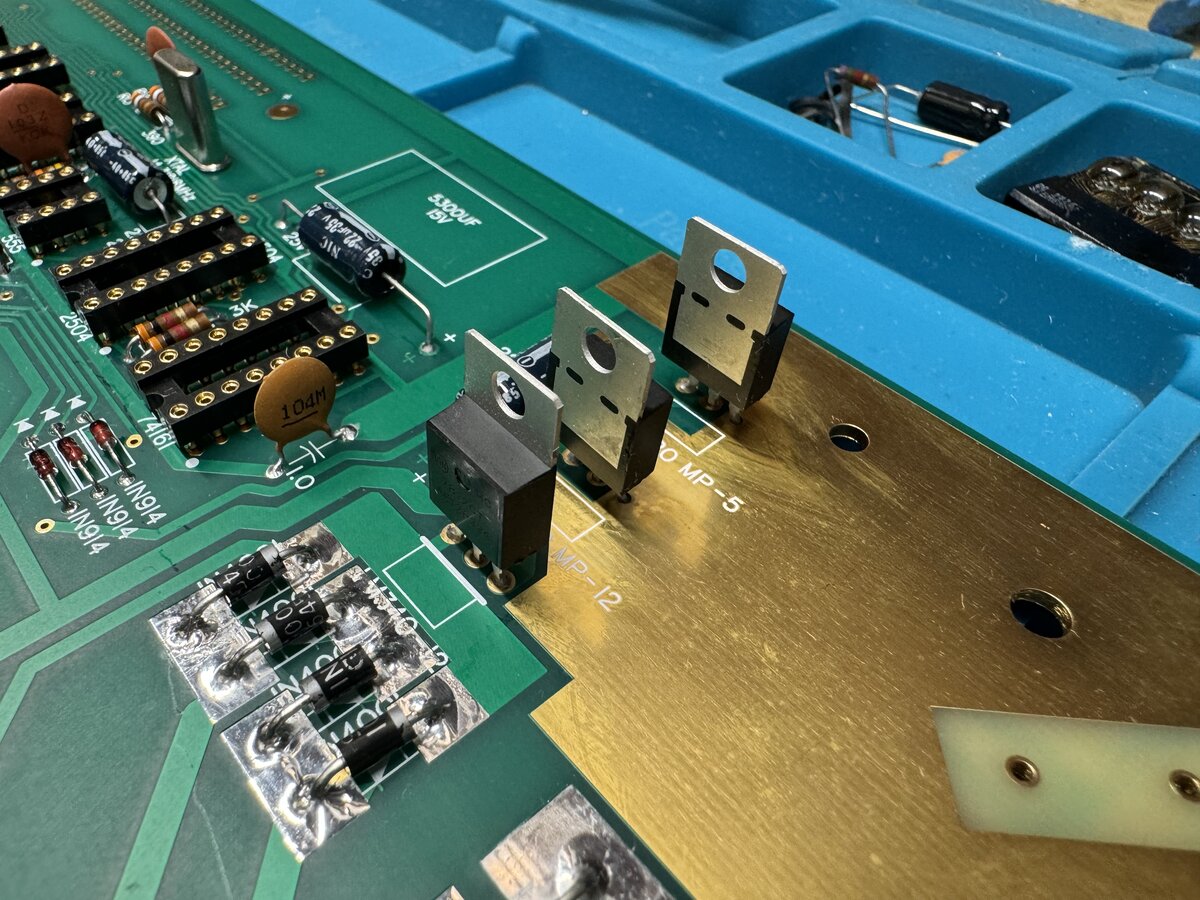
Another viewpoint with the small regulators.
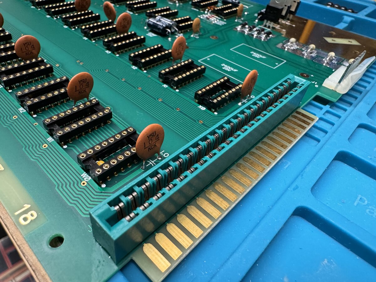
The edge connector was also installed. Note that its black markings go away with isopropyl alcohol! It’s not a problem. Also, the side with numbers and the one with letters are marked on the connector, so you might want those to match, even though the connector is, as far as I can tell, symmetrical.
Cleaning the board
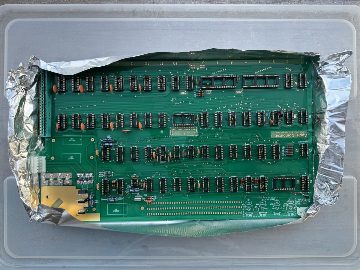
Once all of this is done, you can clean the board of flux thoroughly. I had already done some spot cleaning. The reason to do this now is that most components are still low-profile, and cannot be damaged with isopropyl alcohol. I used a flat tray lined with aluminium foil, filled it with isopropyl alcohol, and let the board soak for a few minutes. I then used a toothbrush to clean the board. I used compressed air to dry it. I also have KimWipes to clean the board, which come in handy in many cases.
Last components
Finally, you can install the last components. For the large Sprague capacitors, Uncle Bernie, again, has some nice tips. I used double-sided 3M tape to affix the capacitors to the board. This provides some mechanical stability, and also makes it easier to solder the capacitors.
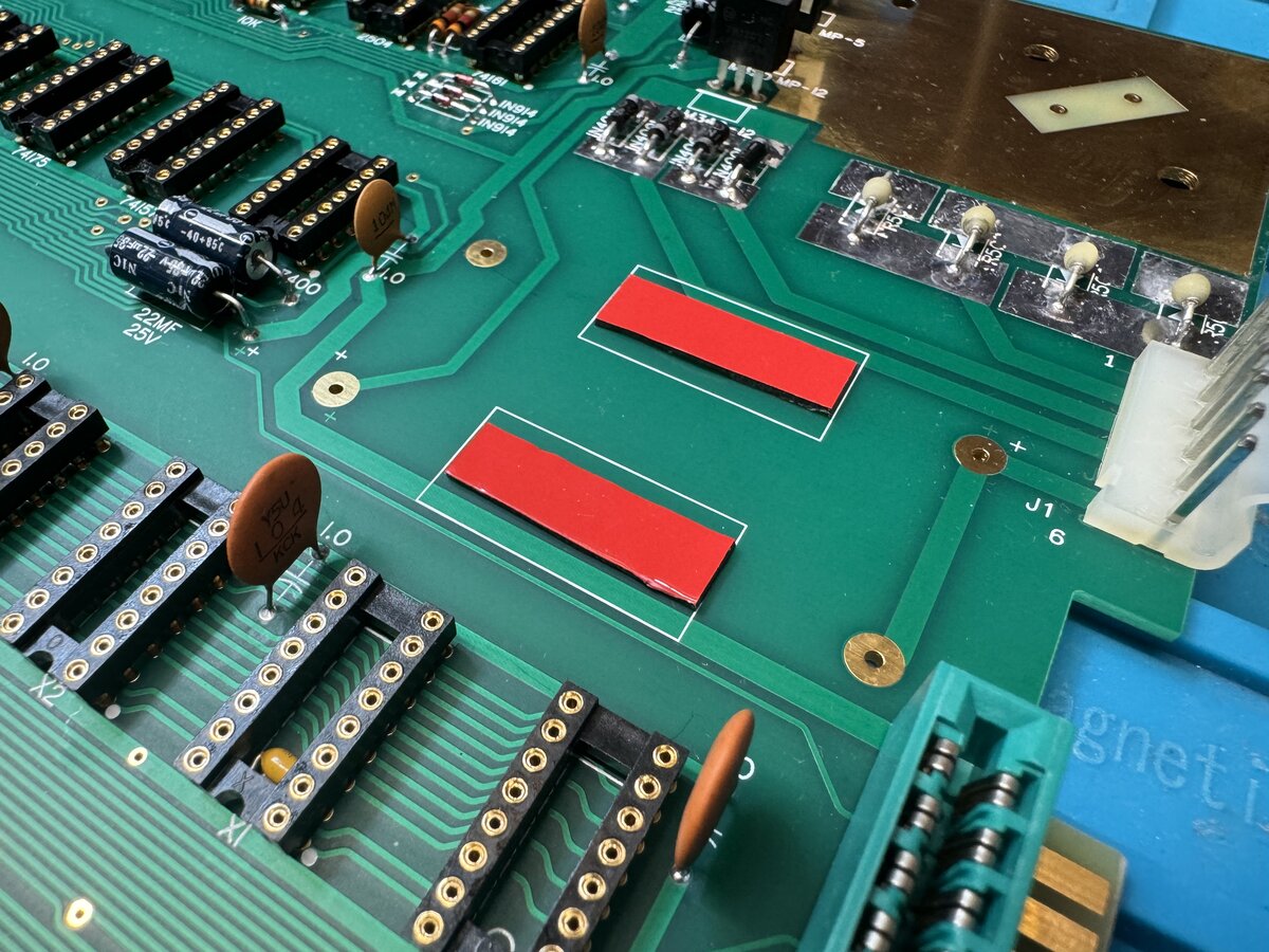
Here is one of the capacitors positioned.
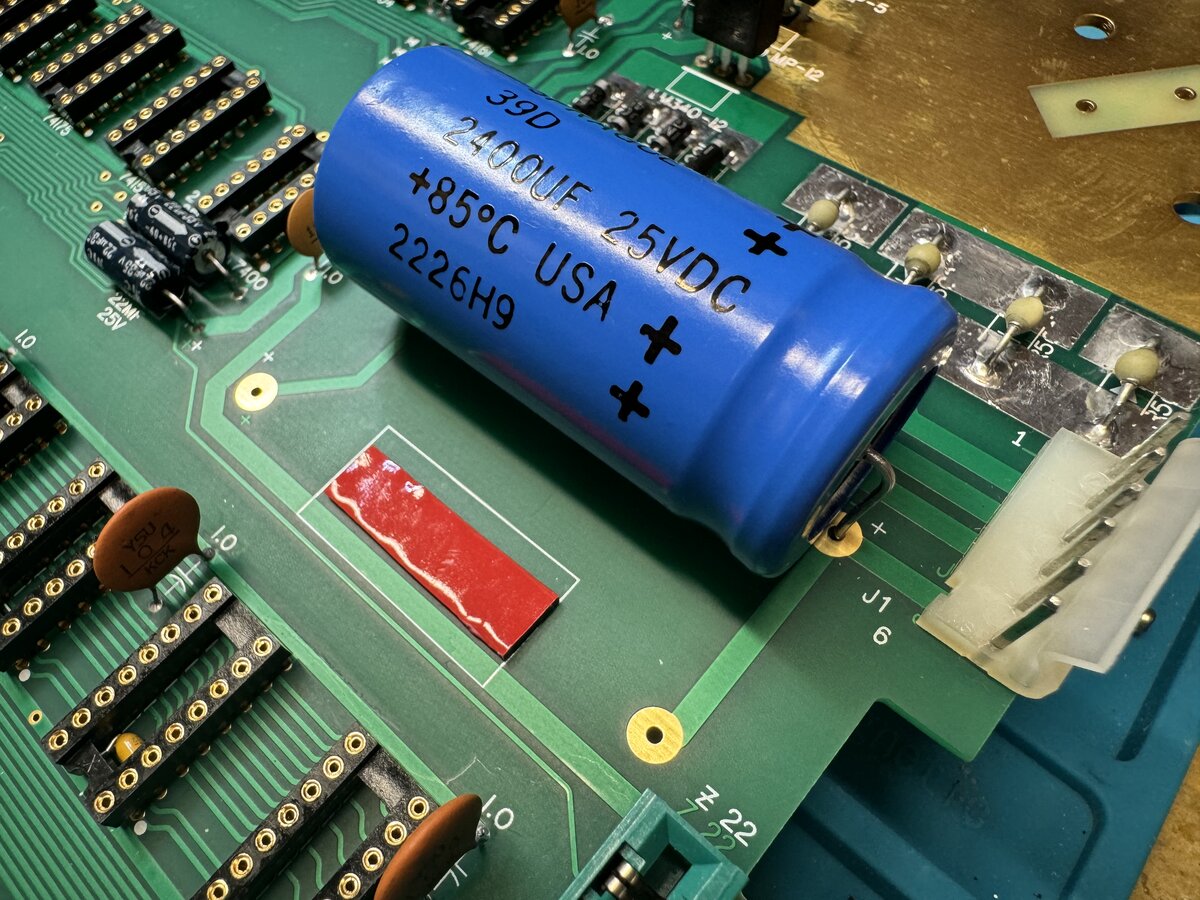
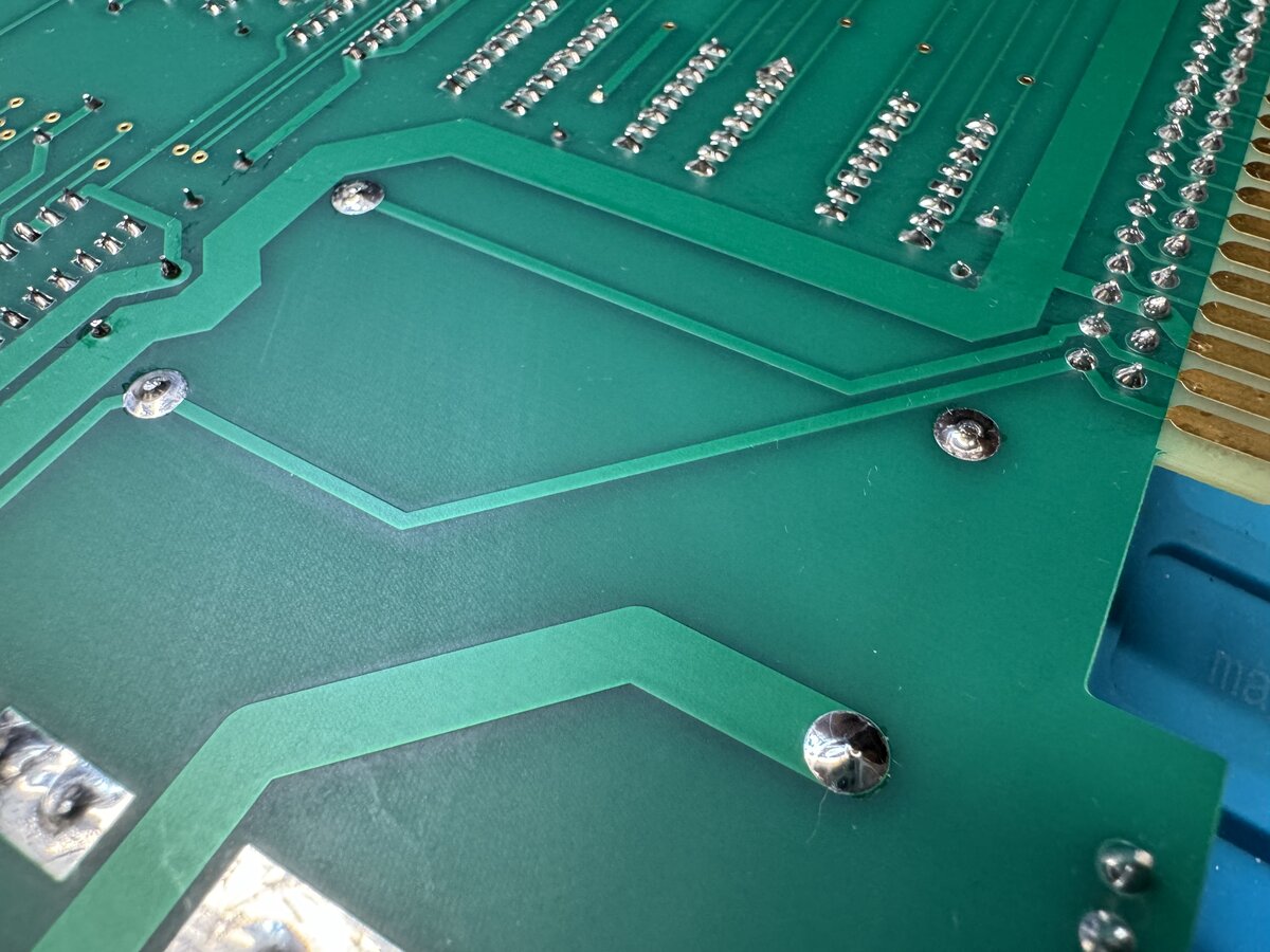
Here are some nice solder joints under the board, covering the pads entirely.
Here are two of the Sprague capacitors installed.
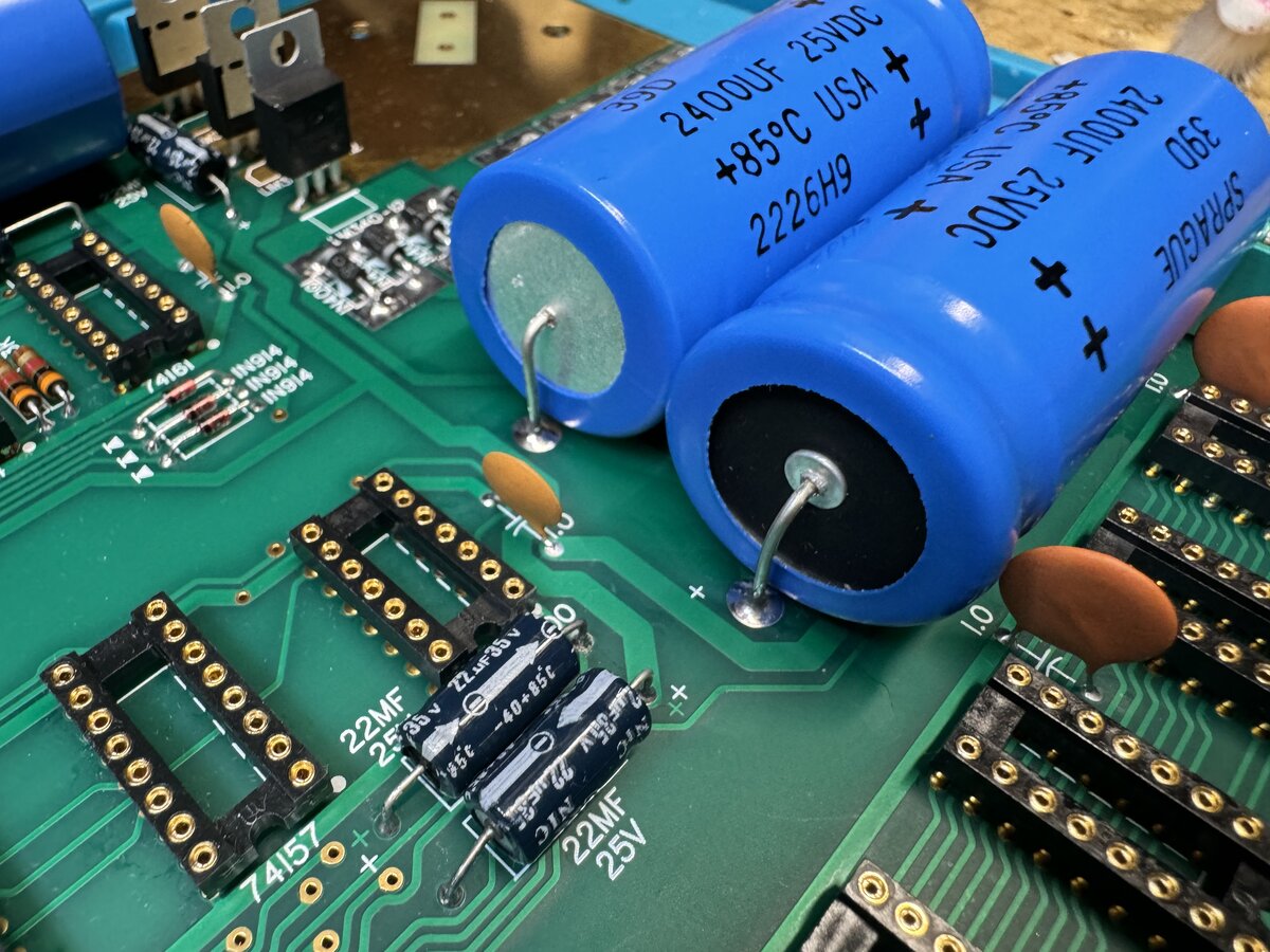
I also soldered the remaining reliability decoupling capacitors that cannot be installed inside sockets due to the fact that said sockets do not provide access to the correct voltages.
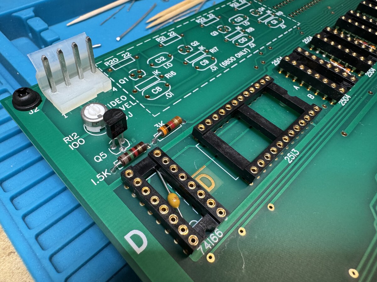
I soldered the trim potentiometer for the video output, and I checked its pinout using a multimeter.
For the large LM323 regulator, which is fitted with a large heat sink, I used thermal paste.
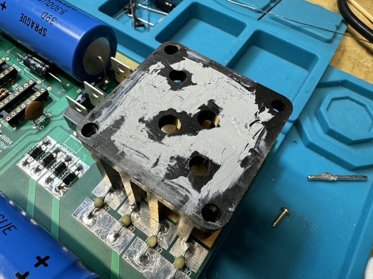
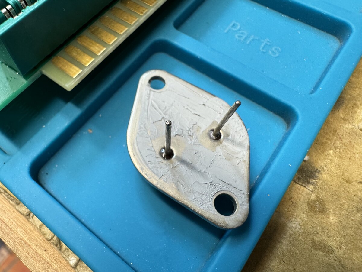
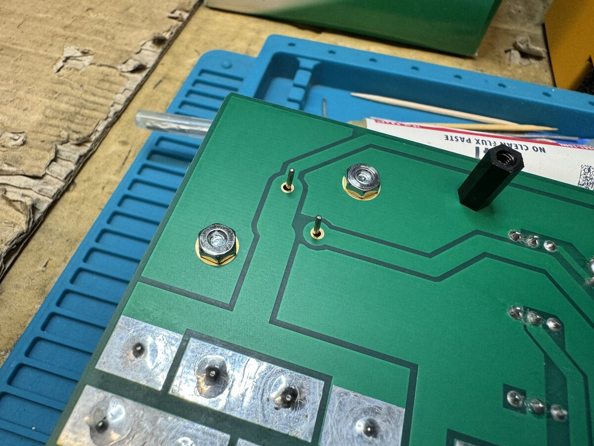
I used temporary screws to hold the regulator and heat sink in place while soldering it. I later replaced the screws with proper ones.
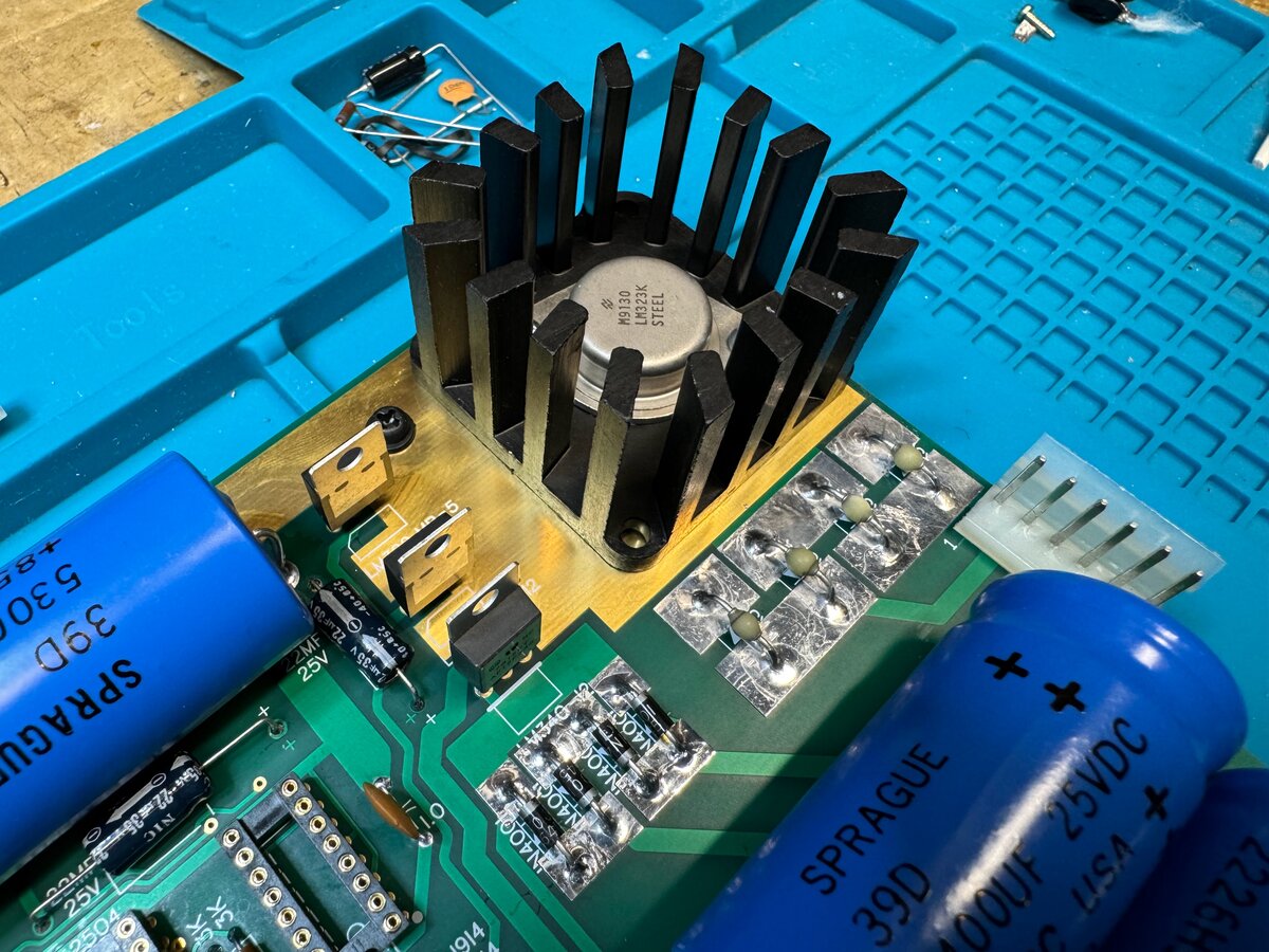
Here is the LM323 installed in the power section of the board.
There are a few solder bridge jumpers to install. I protected the golden tracks around for safety. You have to install the ones marked 6502, and the “No DMA” one.
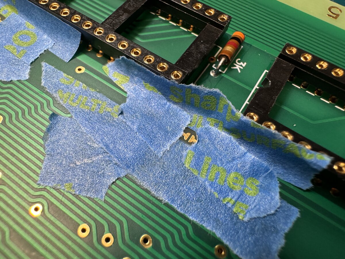
I checked the bottom of the board with a magnifying glass for any type of issue: cold joints, solder bridges. And I did find one solder bridge, which I fixed!
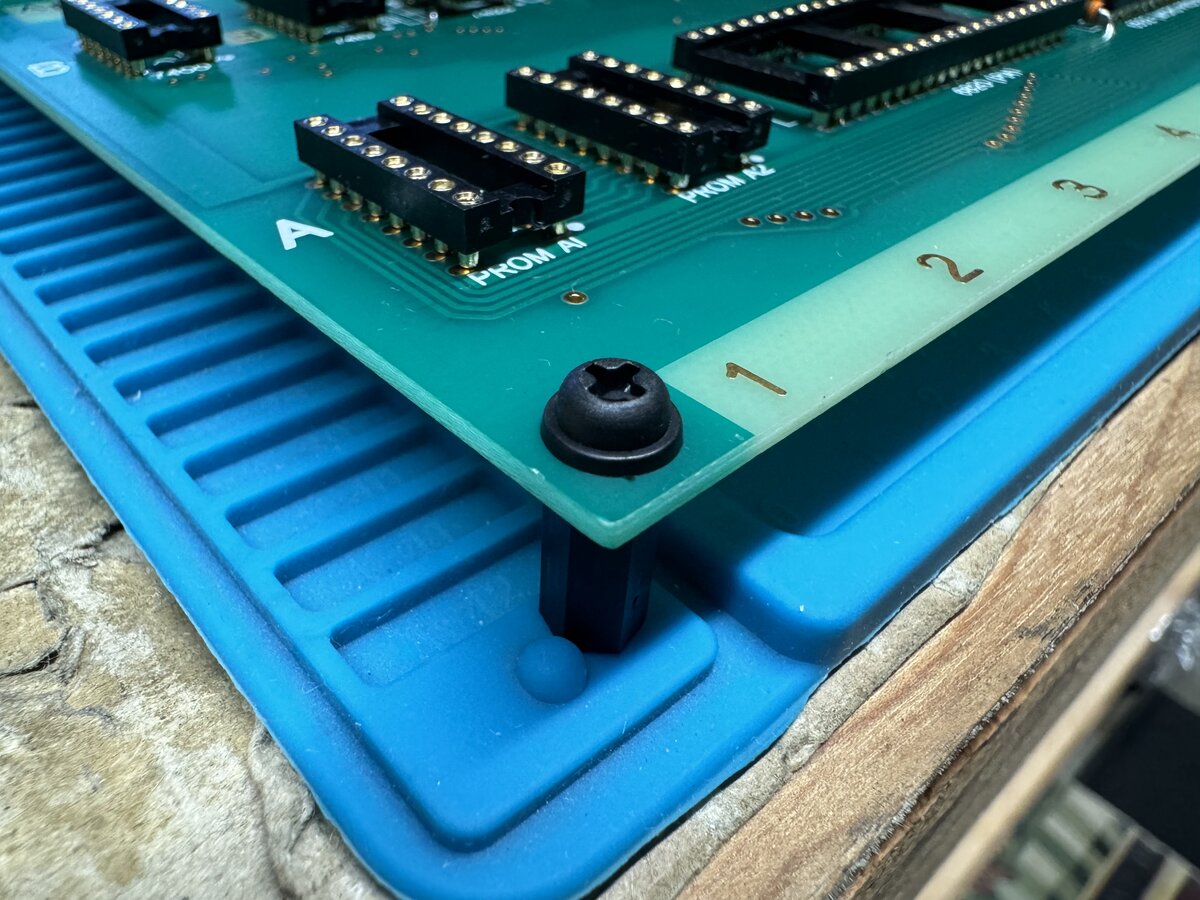
I installed some plastic spacers. I might put something more sturdy in the future.
First power-up
With all the components except the ICs in place, it was time to perform a first power-up!
I discussed the power supply in a previous post. It was ready to go. I plugged it, turned it on, and hoped no smoke would come out from the power regulators and capacitors. I measured voltages on all IC sockets chips and the keyboard connector: they were all good!
This step might sound a little paranoid, but the last thing you want is to fry ICs that are hard to find and expensive. Also, it is a confidence booster.
Testing the 2519 replacement
I discussed testing a large number of the chips in a previous post. But the Retro Chip Tester Pro cannot test the Signetics 2519, or its replacement board. But I wanted to check that it worked before risking putting it on the Apple-1 board. So I made, again, a custom tester for it, using a Raspberry Pi Pico. I wrote some simple software, in C, to test that I could write 40 6-bit words into the shift register, and read them back in “recirculate” mode. Here is my tester. I needed to use a stack of IC sockets to raise it, and I connected also GND to pin 7 of the 7400 socket.
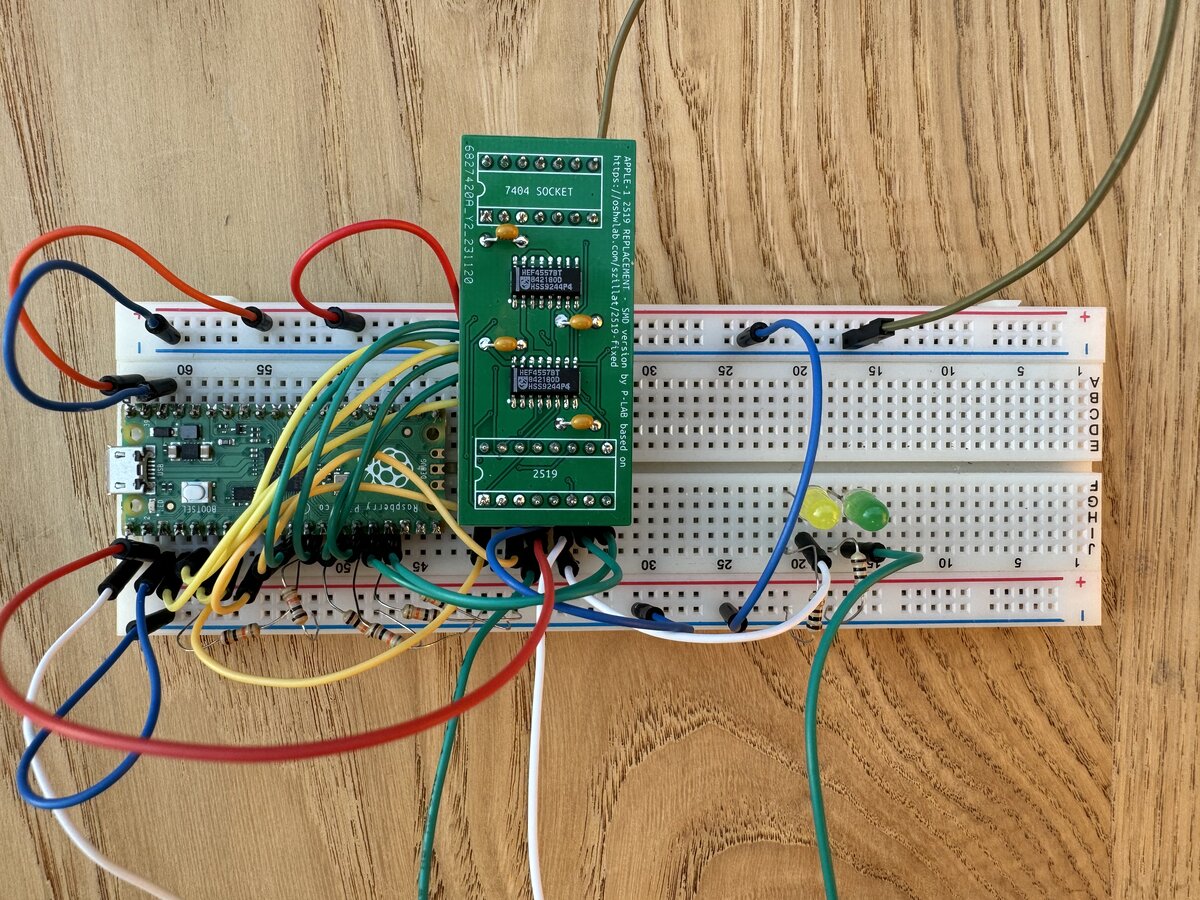
It didn’t work at first. Of course, I made numerous mistakes in my test program. Finally, I got some results, but they indicated failure of some bits. I took out the board and examined it better under a magnifying glass, and noticed some poor solder joints. I fixed them, and then my tests passed!
NOTE: The 2519 board could be put underneath the board, with appropriate sockets. For now, I am 99% ok with it on top.
UPDATE: I have pushed the source code for the tester to GitHub.
Integrated circuits
I finally installed all the ICs. I had initially ordered the 74xx series ICs from Unicorn Electronics. Note that those are the plain 74xx series, not the “newer” 74LSxx series. In any case, because I later separately acquired a lot of 74xx series chips (see Part 3: The Retro Chip Tester), I went through them and picked some older and nicer ones when I could.
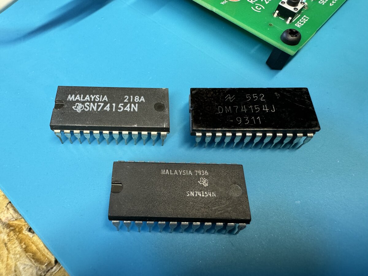
I installed all the chips. This went well, except I bent some pins on a DRAM chip. I had a spare, so I used that one (and the one with bent pins will now be a spare).
Thd Apple-1 has an interesting feature: a memory map section on the board, which is configured with jumper wires. The output of the address decoder outputs a signal for each 4KB block of the 64 KB of memory, and you can map memory and devices to these blocks. Here is the memory map. The following table shows the typical memory mapping for the Apple-1:
| Label | Memory/Device | Address | Notes | On connector |
|---|---|---|---|---|
| Y | Woz Monitor PROM | 0xF000 | Typically unchanged | No |
| Z | 6820 keyboard interface addressing | 0xD000 | Typically unchanged | No |
| R | Cassette interface PROM and hardware mapping | 0xC000 | Typically unchanged if used | Yes |
| S | Auxiliary | - | Typically custom | Yes |
| T | Auxiliary | - | Typically custom | Yes |
| W | Second onboard 4K bank of dynamic RAM | 0xE000 | Sometimes changed | No |
| X | First onboard 4K bank of dynamic RAM | 0x0000 | Typically unchanged | No |
This is how things are configured typically on the board:
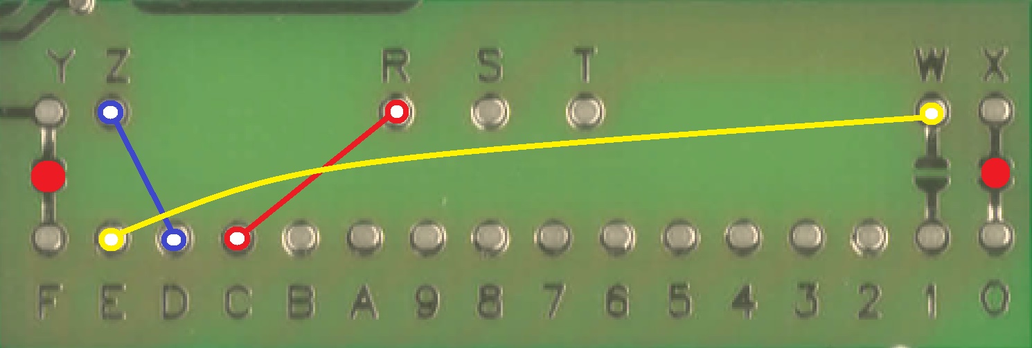
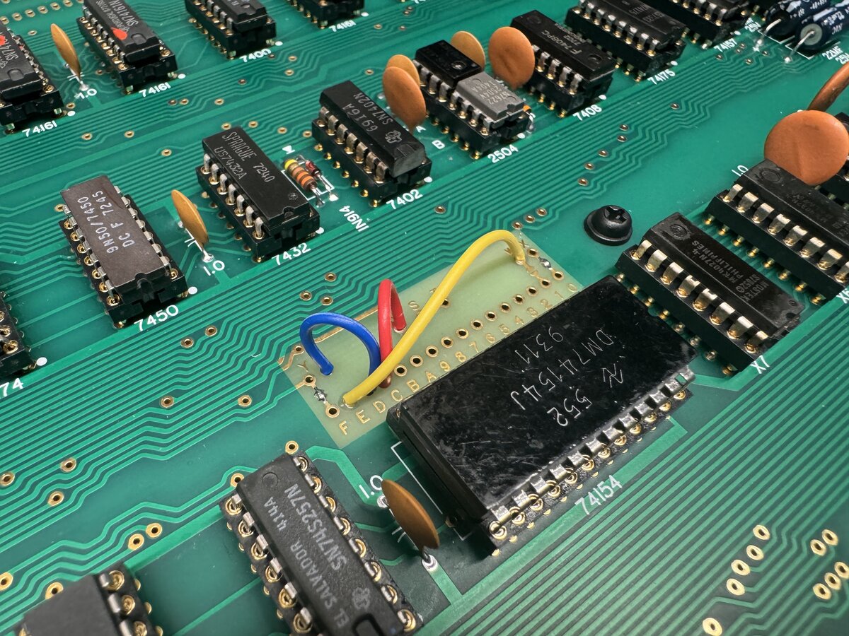
I soldered the memory map jumpers following this standard setup.
Conclusion of part 4
This major step required research, care, and patience. A couple of small challenges had to be overcome, but the board is now fully populated and includes the “reliability mods”.
As usual, you will find more pictures in this photo album:
Part 5 covers the monitor, keyboard, power-up, and troubleshooting.

Comments powered by Disqus.