This is part 5 of a series of posts about building an Apple-1 reproduction in 2024 (and 2025). See also:
- Building an Apple-1 Reproduction in 2024 - Part 1: Components
- Building an Apple-1 Reproduction in 2024 - Part 2: Power Supply
- Building an Apple-1 Reproduction in 2024 - Part 3: The Retro Chip Tester
- Building an Apple-1 Reproduction in 2024 - Part 4: Assembly
- Building an Apple-1 Reproduction in 2024/2025 - Part 6: C Programming
- Building an Apple-1 Reproduction in 2024/2025 - Part 7: The Audio Cassette Adapter
Hitachi monitor
It’s nice to have the main board populated, but I needed a way to connect to the video output, or else how would I know if things were working? For this, I had two options:
- An LCD monitor with composite input that I used with my VIC-20.
- A 1975 Hitachi monitor that I bought at a flea market this year (see also Part 1).
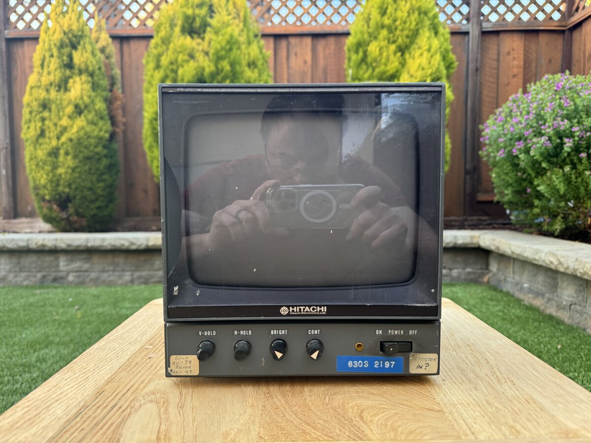
Of course, the Hitachi monitor would be perfect for the Apple-1, but I hadn’t really tested it. So first, I tried to connect it to my VIC-20. At that point I realized that the Hitachi doesn’t have standard RCA or BNC connector on the back. Fiddling with an RCA cable, I did manage to see some image on the Hitachi, although rotated 90 degrees. This indicated that the monitor was at least partially working!
Searching online, I found out more about the connectors on the Hitachi: those are older-style “UHF” connectors. Luckily, I found some NOS BNC adapters on eBay (BNC(F)/UHF(M)), and ordered a couple of them. I actually only needed one, but I wanted to have a spare, or one for the output connector, for looks.
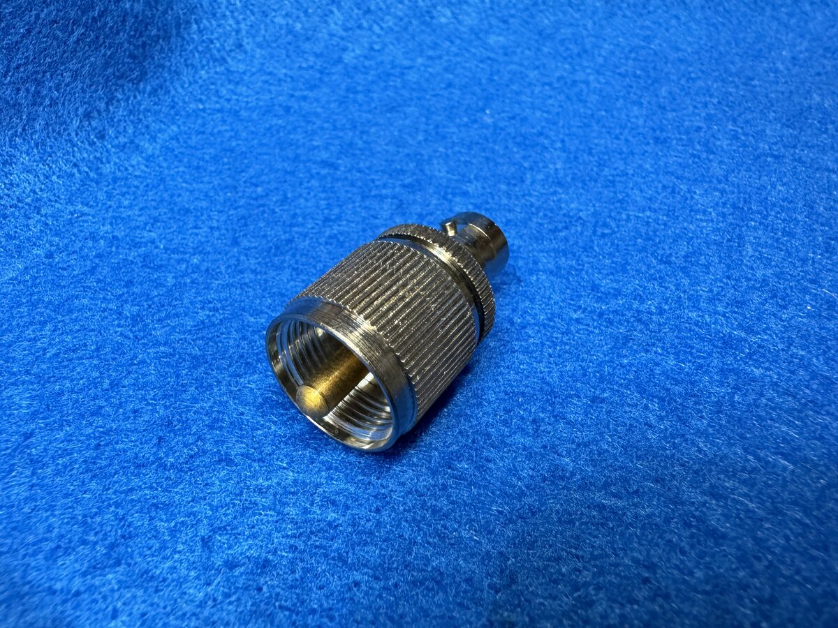
Luckily, they fit perfectly, and they were in excellent NOS condition.
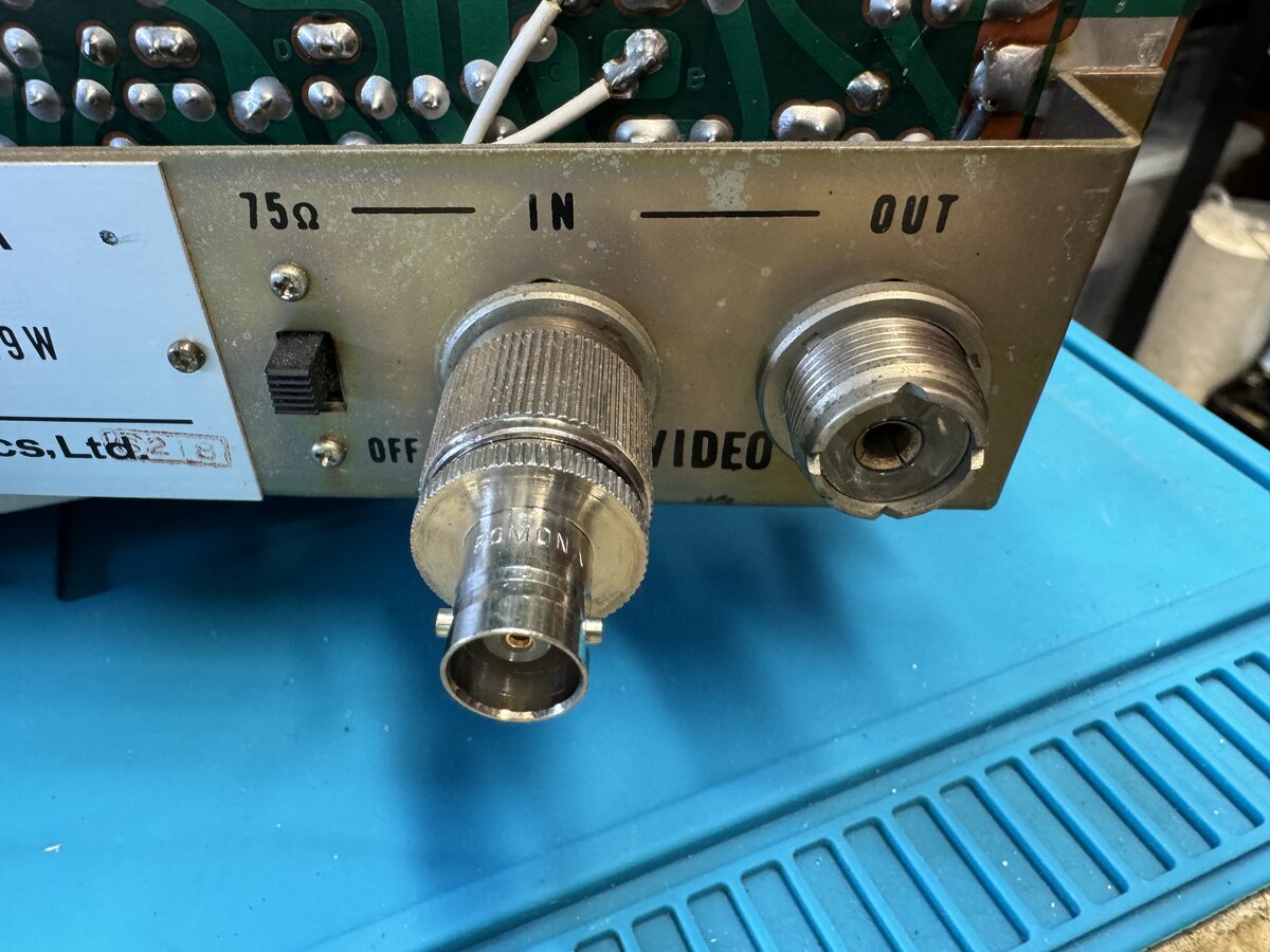
I used the 75 Ohm setting of the monitor.
I opened up the monitor. The back of the monitor opens easily with 4 screws.
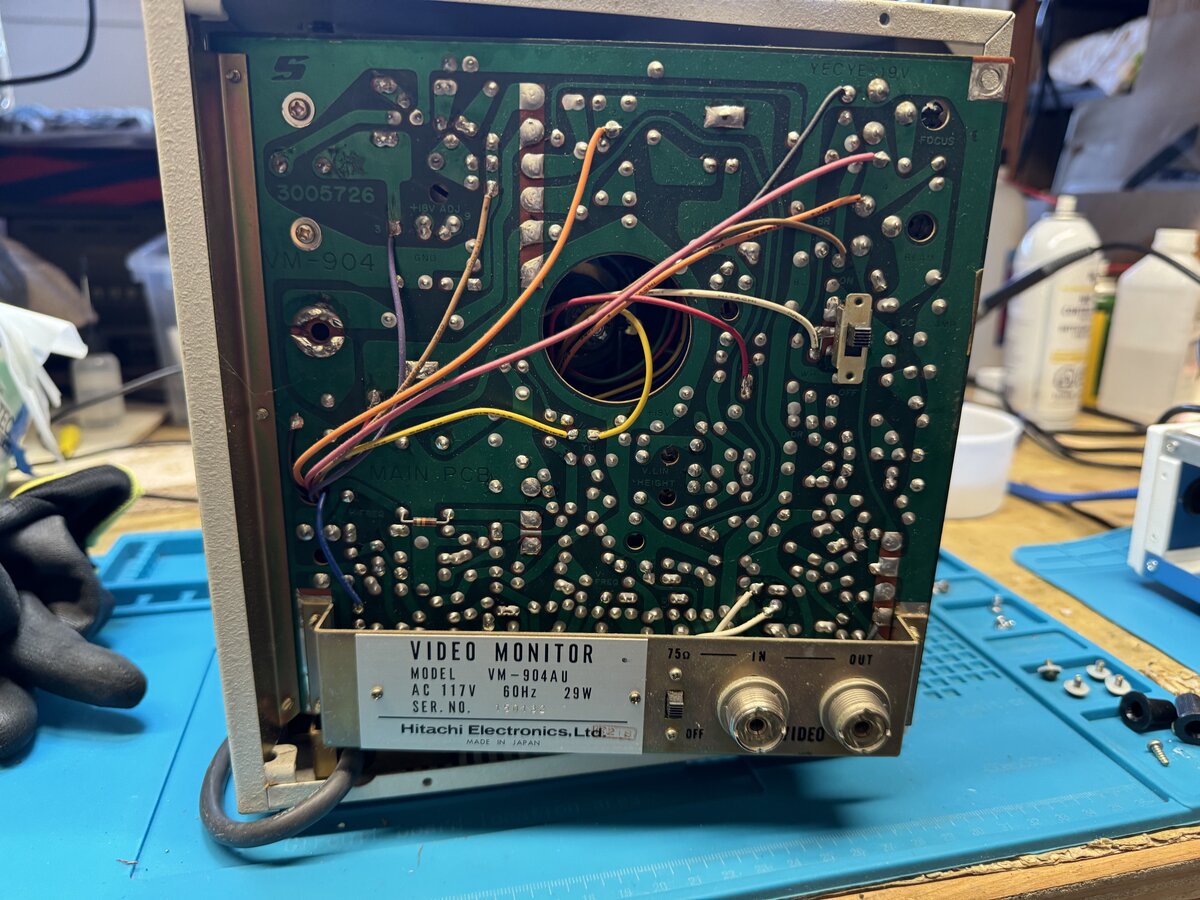
From there, another 2 screws allow you to swivel open the main PCB.
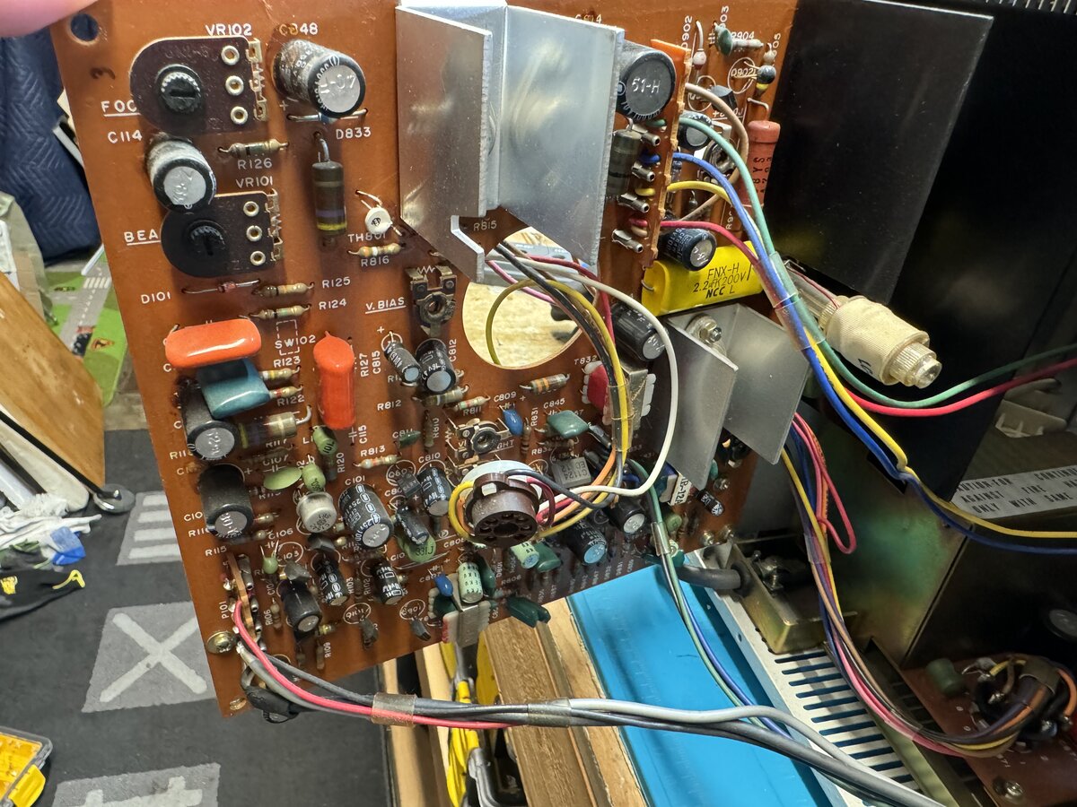
You can access the back of the CRT (Cathode Ray Tube) from there.
PSA: CRTs can store a significant electric charge even when unplugged. Be careful when working around them. Don’t touch them if you don’t know what you are doing.
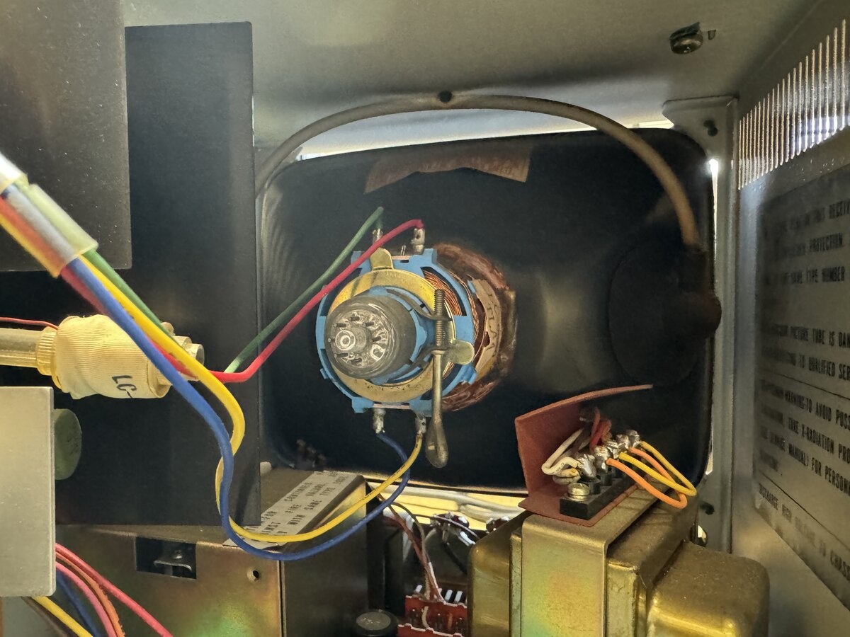
I removed the knobs and front panel:
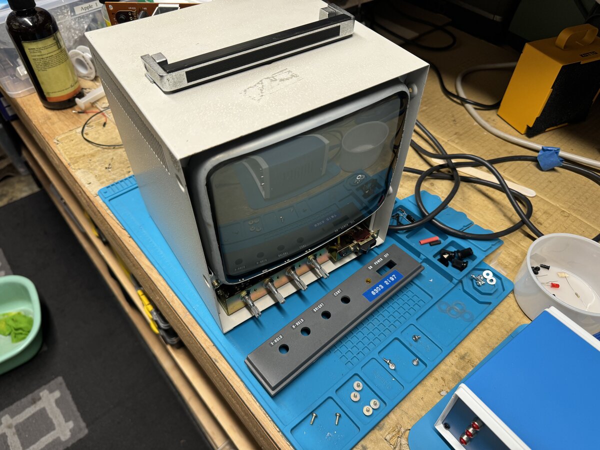
The main front panel was lined with crumbling foam tape which I cleaned.
I cleaned the inside of the monitor with compressed air.
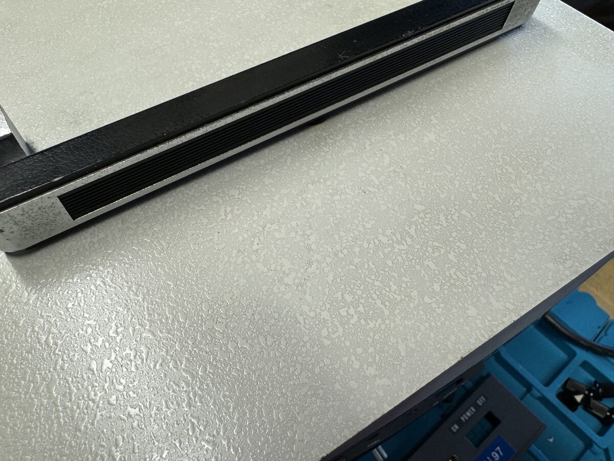
I used Hoppe’s #9 to remove the hardened glue residue on the top cover and sides.
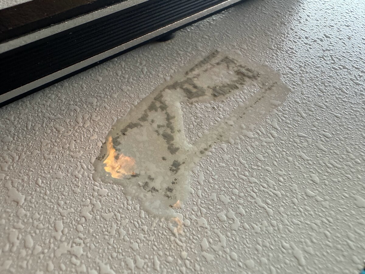
I cannot recommend enough the following products and materials:
- Hoppe’s #9
- plastic razor blades
- Goo Gone
Most people might be aware of Goo Gone, but personally I only discovered Hoppe’s #9 thanks to my work on typewriters. It’s originally a gun cleaning product, but it has other uses, and works marvels where other products fail. You have to be a little careful with Hoppe’s #9, as it can remove paint. But I have found that on plastics, and even on most painted surfaces, it can remove all sorts of stains and hardened materials as safely as can be.
I followed the following process:
- apply Hoppe’s #9 with a q-tip
- let it sit for a while
- carefully scrape with a plastic razor blade
- wipe
- repeat
This removed the glue residue entirely.
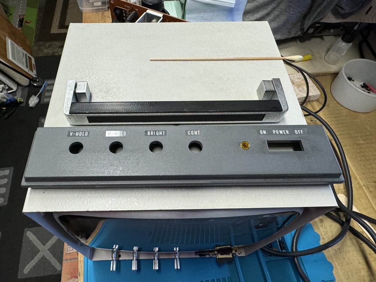
I also cleaned the buttons cover. I used some plastic rejuvenator on the plastic parts, which helps a little for the looks.
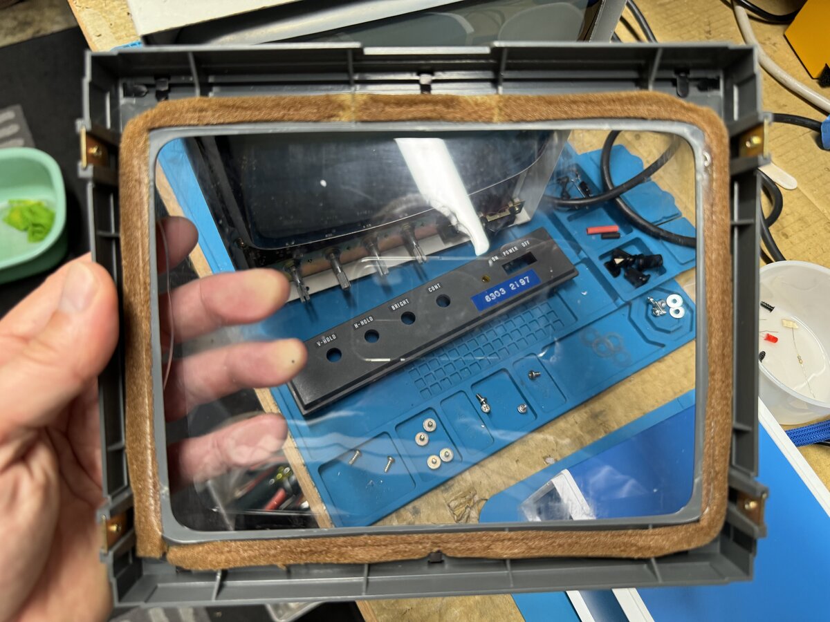
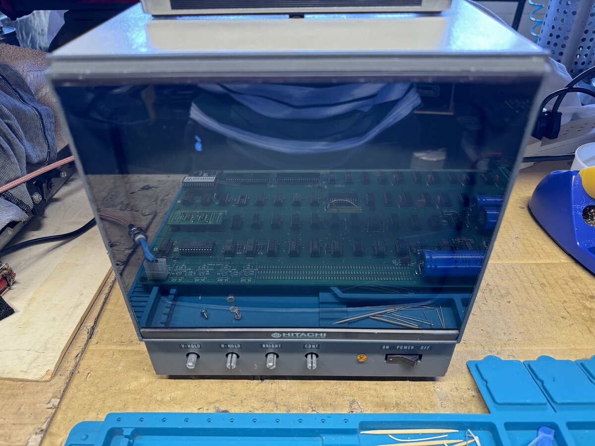
The front panel of the monitor was broken. This was tinted plastic. I went to Tap Plastics and got a piece of the only tinted plastic they had, for about USD 11. This was thicker, but I went with it anyway. They cut it to a perfect size based on my original plastic part. It is definitely too thick, and a thinner piece would be better. But unless you know about it, you won’t notice that the bevels are not quite straight.
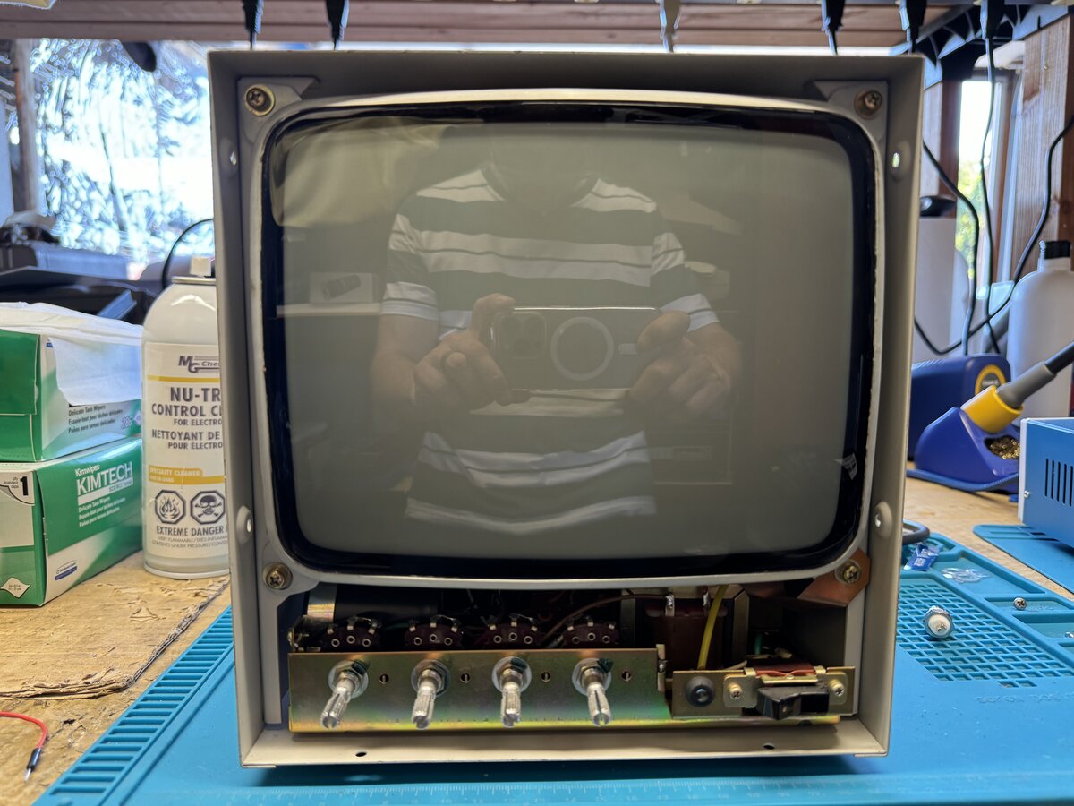
Here is the monitor cleaned but without its front panel.
Here is the new tinted plastic installed:
I mentioned above that the image on this monitor, during a quick initial test, appeared to be rotated 90 degrees! I wondered if:
- there was a setting for this (unlikely)
- or whether it was just the yoke that someone had rotated
Once the monitor was open, I was able to access the yoke. I compared the yoke position with a picture of a similar monitor I found online. It seemed to confirm that the yoke was rotated 90 degrees. I loosened the screws that keep the yoke in position, rotated it (carefully, with gloves), and got a properly-oriented image!
First power-up
With a working monitor, it was time for the first real power-up of the board with all of its ICs populated.
Mike Willegal, pioneer and hero of the Apple-1 reproduction scene, used to recommend powering-up the Apple-1 sections separately: first the terminal section, and second the computer section. Uncle Bernie, in the context of his kits, has recommended against doing this, and going straight for a full power-up. I decided to follow Uncle Bernie’s advice: even though I was not working from a kit, I had tested most chips with the Retro Chip Tester. It seems that half-populating the board and powering it up is also not entirely risk-free.
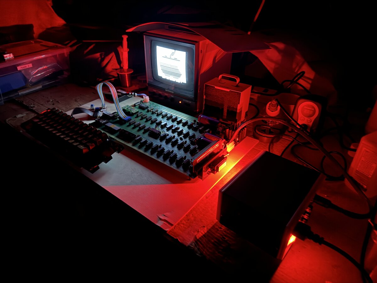
I plugged the power, and I saw something on the Hitachi monitor! But I didn’t see the clean, blinking pattern you are supposed to see. There were characters, but they were flickering in a funny way. Unfortunately, I don’t have pictures or videos of this state of affairs, as I was too busy and excited.
Indeed, you are supposed to see an alternated series of “@” and “_”, with the “@”s blinking at the cursor blinking rate. This, at least, is the most common state of the video section after a power-up, but it can also be a little different as it is not the result of a proper reset logic.
I used my vintage HP oscilloscope to measure some signals:
| Component/Pin | Measurement | Observations |
|---|---|---|
| 74123 pin 13 | 496 ns | a little long, but pretty close |
| 555 pin 3 | 4.4 µs (225.255 kHz) | definitely wrong! |
| Φ3/Φ4 | ~500 kHz | good |
| 6502 pin 3 | ~1 MHz | good |
Here is the problematic reading on the 555:
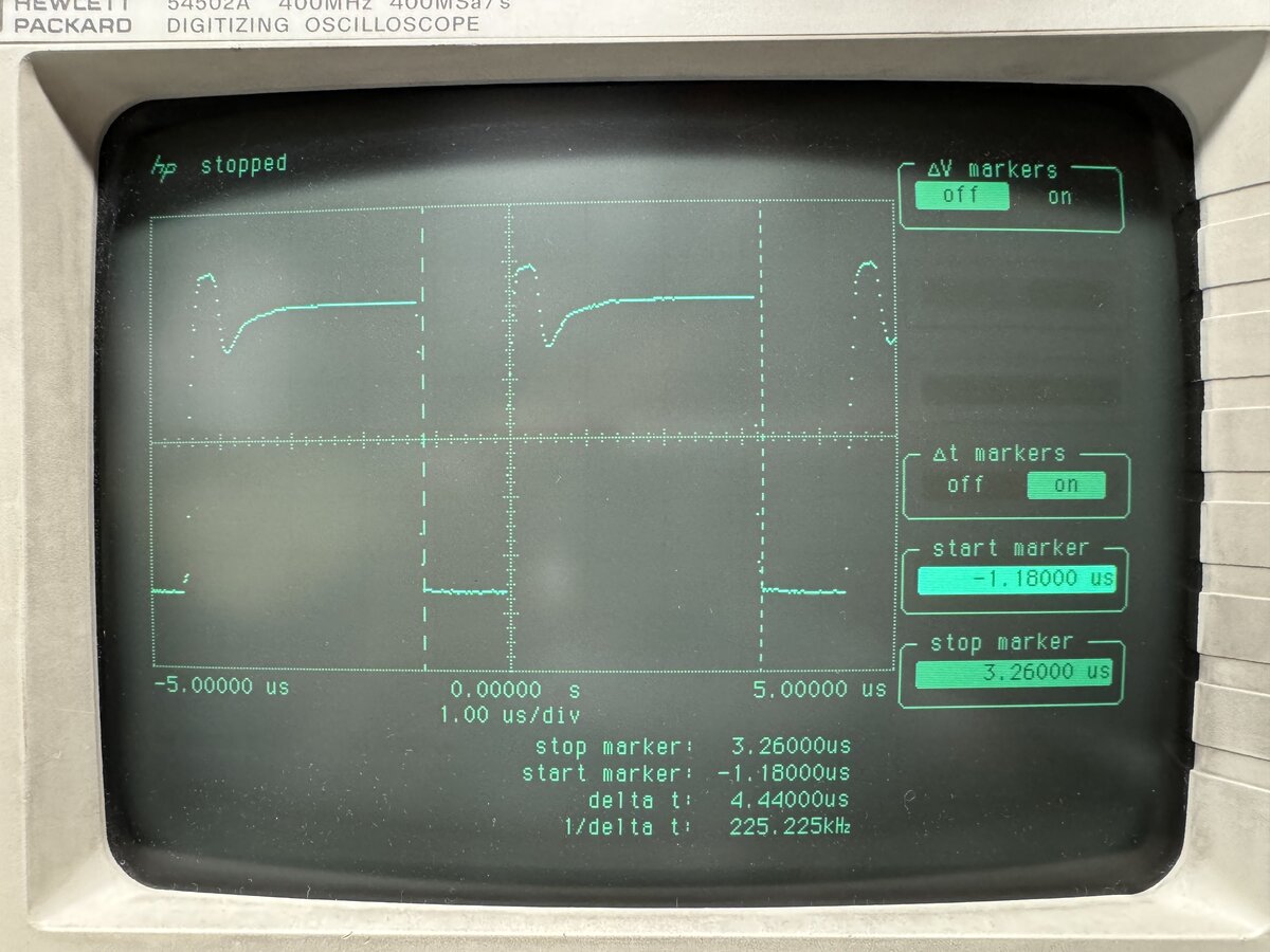
I read here that the “theoretic time period is 457 msec” for the output of the 555. So something was definitely wrong.
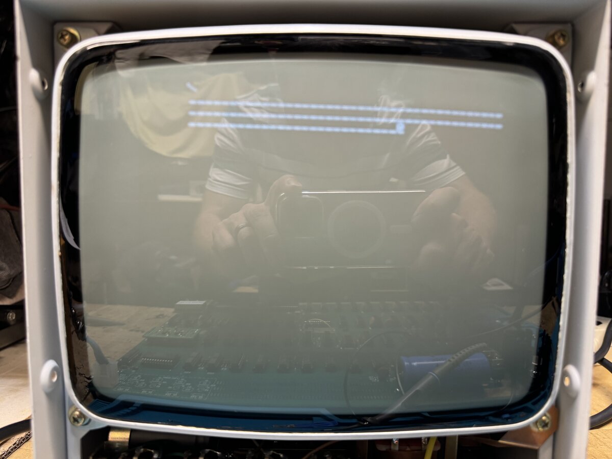
I tried out to power up again. Using wires, I activated the CLS and the RESET signals on the keyboard connector, carefully in order not to cause shorts. This caused the famous (to Apple-1 fans) \ and @ to show!
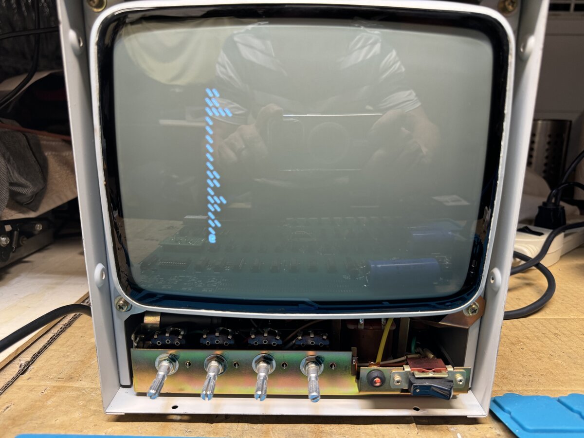
However, the @ was blinking weirdly. I then also used a wire to hit the STROBE signal connected to +5V, and I saw some _s show up. This was great news, as it meant that the CPU was reading from the keyboard connector, and writing to the video section! In other words, it indicated that CPU, PIA, keyboard connector, and display section were all working to some degree at least!
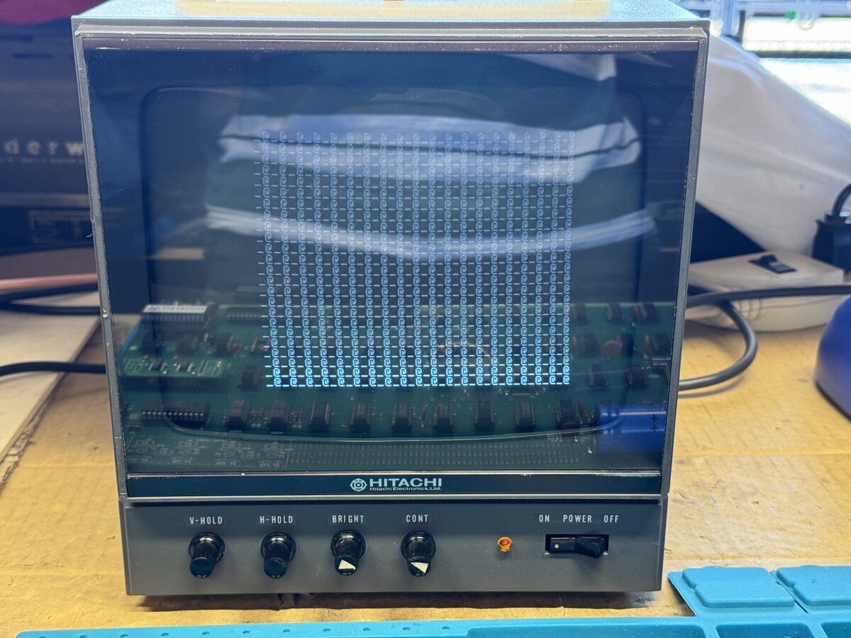
So there was just something wrong with the cursor logic. I tried the obvious first: swapping some related ICs to see if anything changed. Nothing did. I then swapped the 555, and nothing changed. With the 555 removed, I measured in-circuit (which was fine since the 555 was removed) the resistors and electrolytic capacitor around it, and found that the 22 μF capacitor was bad! I removed it, measured it again to confirm that is was bad (and it was), put a new one in, and the blinking worked!
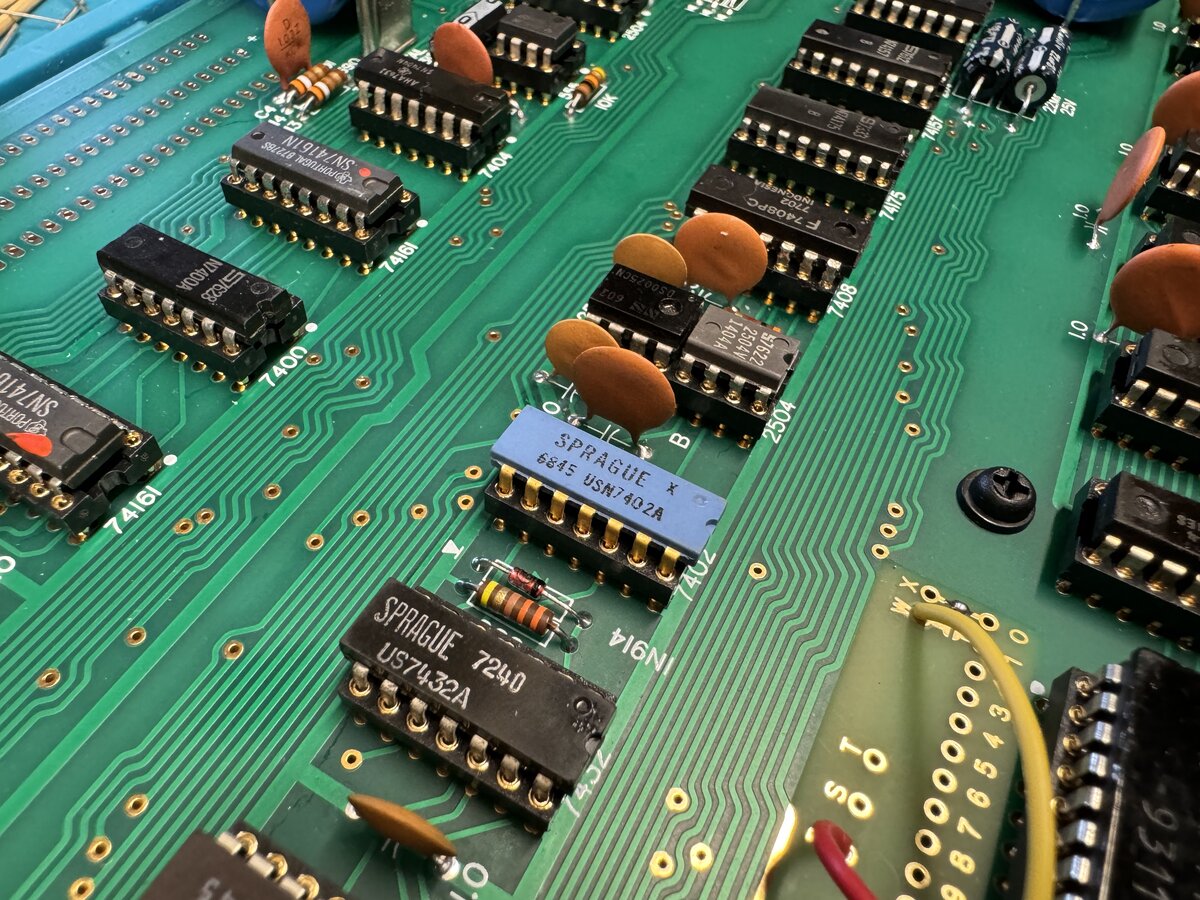
Since things appeared to be working, I decided to put in some older or cooler chips, like this 1968 blue and gold Sprague 7402:
Keyboard
In order to proceed further, I needed a keyboard. Earlier in the project, I had considered building a modern Datanetics keyboard reproduction. In fact, I had already ordered components for that purpose.
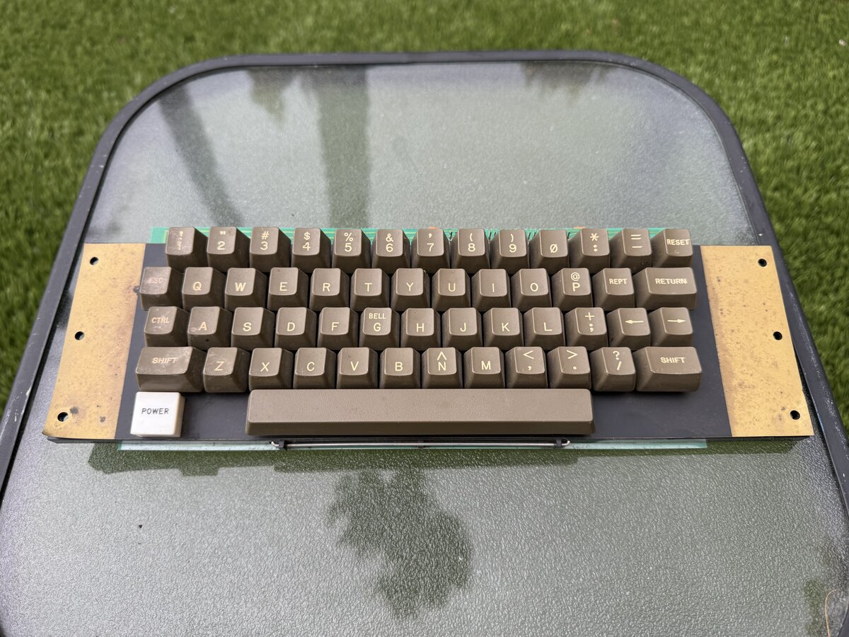
But in August 2024, I found an Apple II keyboard. Note that there are several iterations of the Apple II keyboard. Here is mine:
I didn’t know if it worked, but I had to try it. I started by partly disassembling the keyboard to clean it. Here is the controller board. Sometimes the keyboard encoder fails, but luckily I found out later that mine was good:
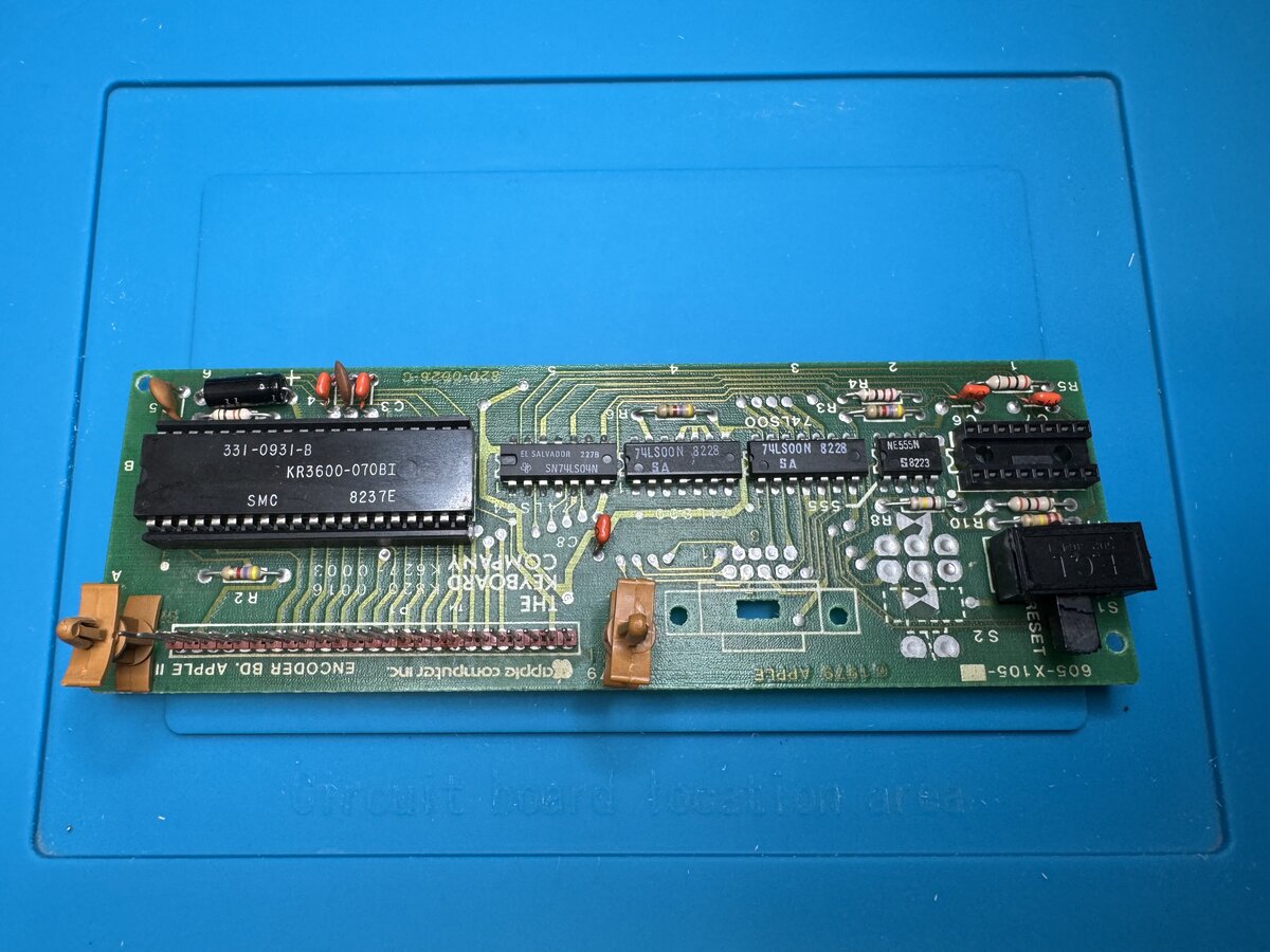
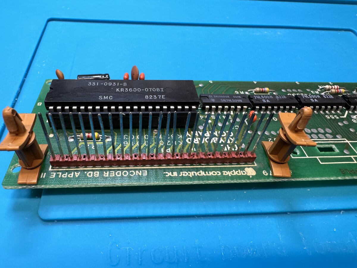
It was hard to pull out the two boards apart, due to this connector being pretty tight:
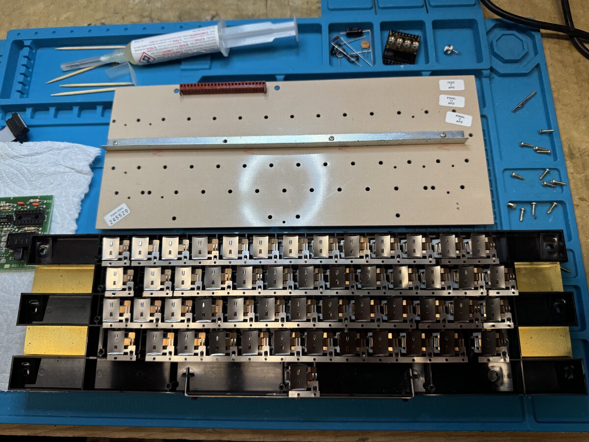
I removed the board under the keys, for cleaning, and also to see how this keyboard was made. As you can tell, you don’t have individually-packaged switches, but a series of contacts:
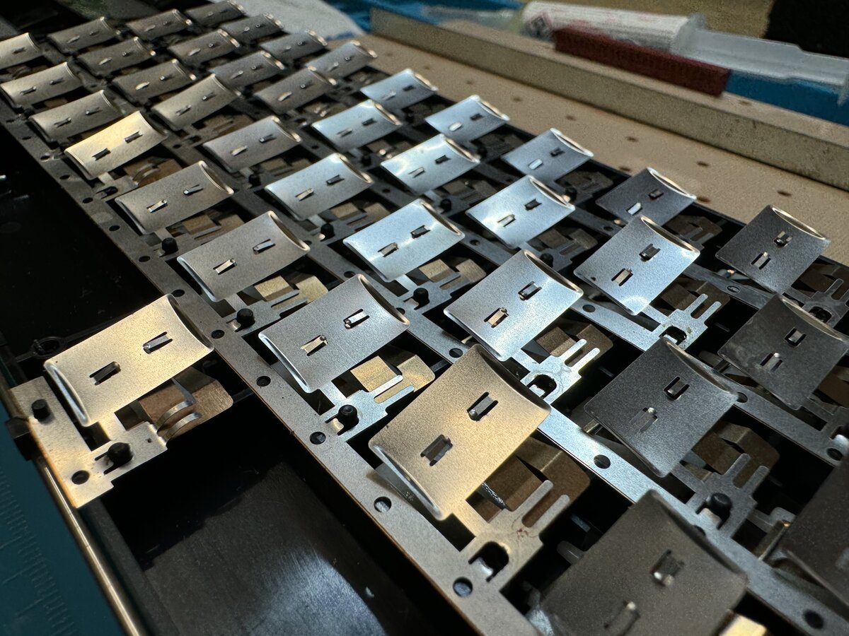
Here is a close-up of the contacts:
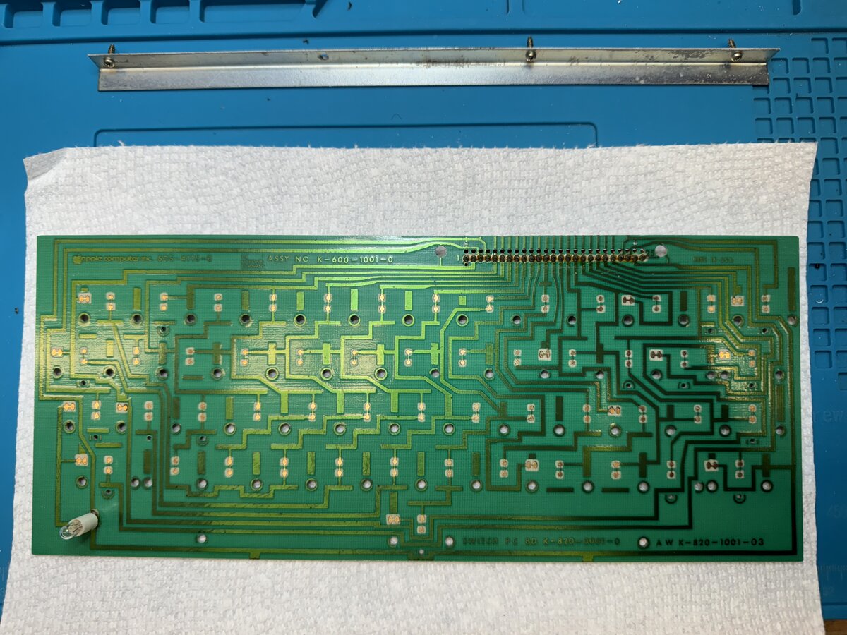
Here is the PCB behind the contacts:
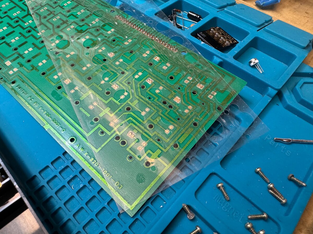
There is a clear maks around the contacts:
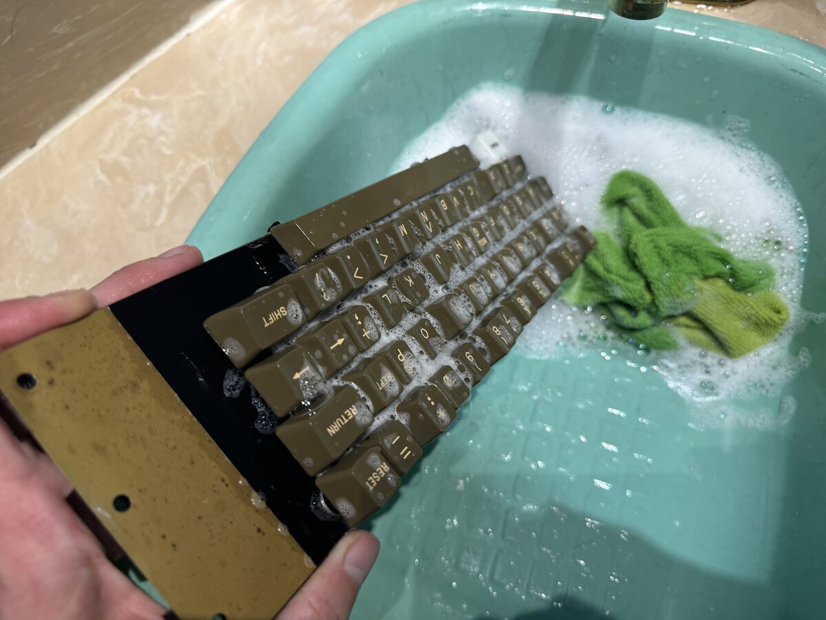
I didn’t want to remove all the key tops, so I decided to just use water and detergent to wash the whole thing. Then I used compressed air to remove all the water, and let it dry.
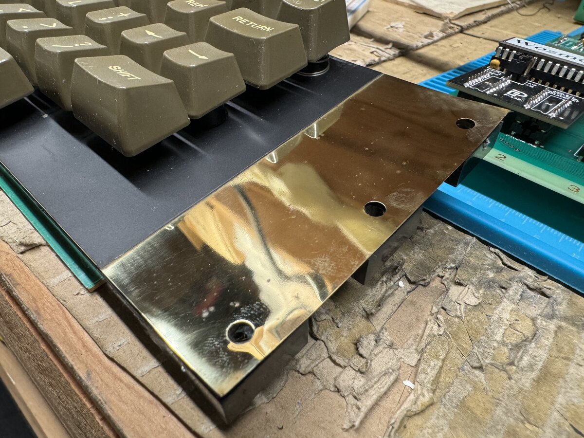
For looks, I later polished the sides of the keyboard, which are made of metal on a membrane (copper?). this looks better than before, where that has significantly corroded.
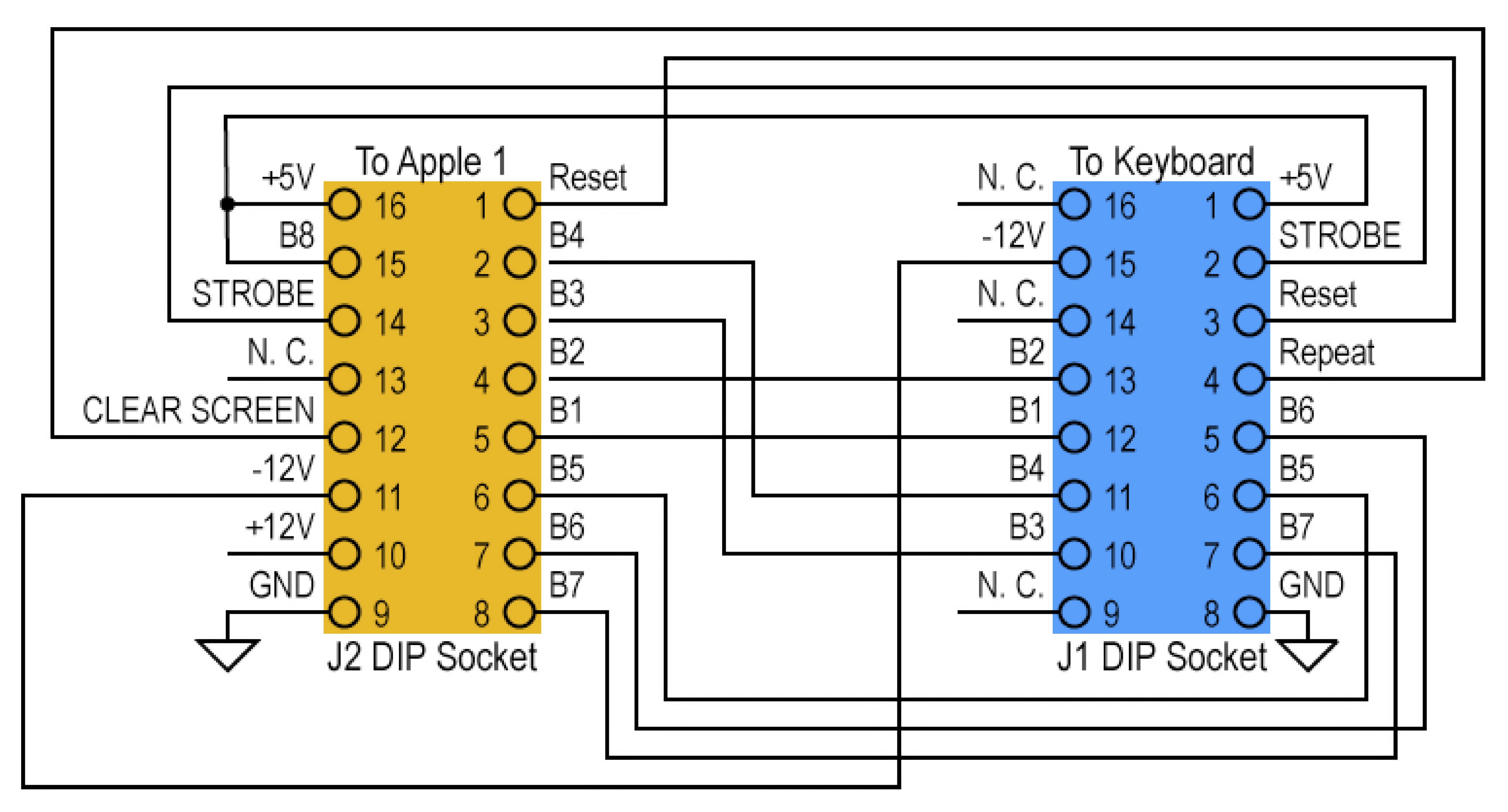
One thing to know is that the connector for this keyboard and the Apple-1 are identical, but the pinout is different. This means that you need to use an adapter. This is easy to do, based on the following diagram made by Wendell Sander, another hero of the Apple-1 scene, in 2010 (which I colorized a little for readability):
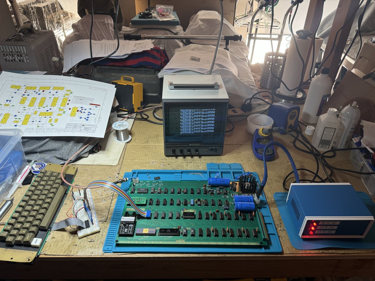
I first built the adapter on a solderless breadboard. Although I didn’t take good pictures, you can see the breadboard on the bottom left of this image.
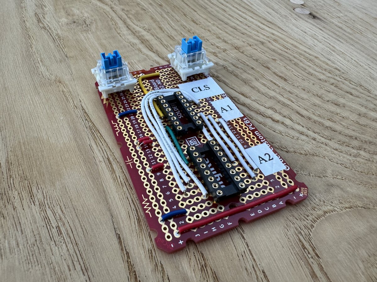
Later, I redid it using veroboard. Here is the veroboard version:
Here is the bottom of it:
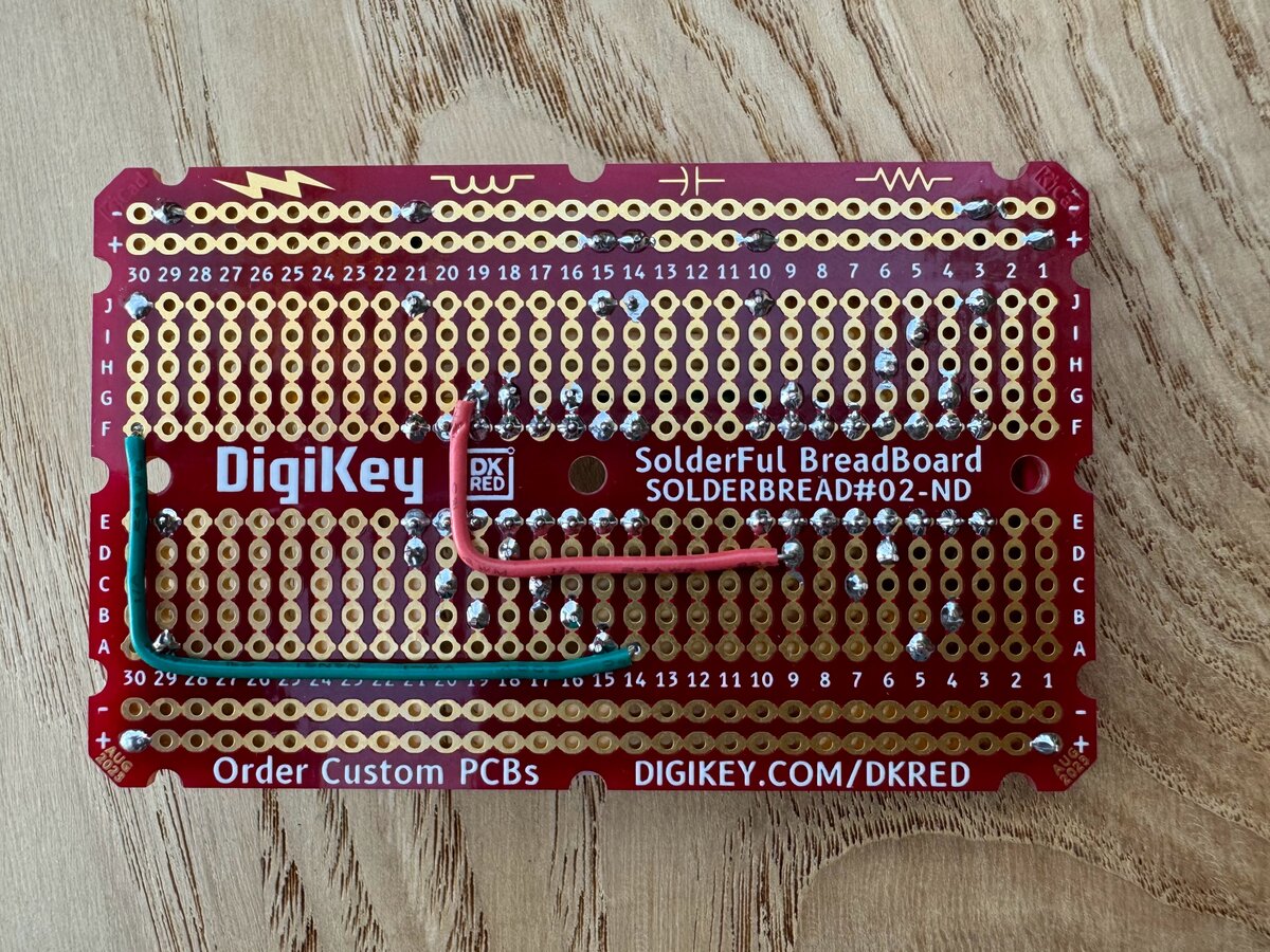
Both the adapters worked! I know they are very simple, but still, it’s always nice when things work the first time.
I had no difficulty making the keyboard connector: you just need to get the correct connectors, a flat ribbon cable, and to sandwich the ribbon in the connector. This requires serious force, but it worked without any issue.
At some point I will design a PCB for the adapter, or use an existing one if I find one. It shouldn’t be hard to do.
As soon as I knew that both the terminal and the keyboard worked, I swapped by PIA with the cool-looking CM602 from Bulgaria:
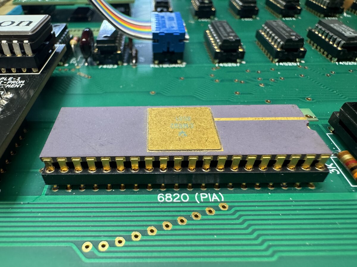
While I bought it untested, it seems to work flawlessly. I like it because, while I am not a gold person in general, the gold cover, line, pins go well with the gold machine sockets and the ENIG PCB.
Now ideally you would want a white ceramic 6502 CPU as well, but those fetch up to USD 2,000 on eBay, so no thanks. I am happy with my 1979 6502A.
First programs
As soon as I had a working keyboard, I entered the test program from the Apple-1 manual. And it worked! Here is the relevant part of the manual:
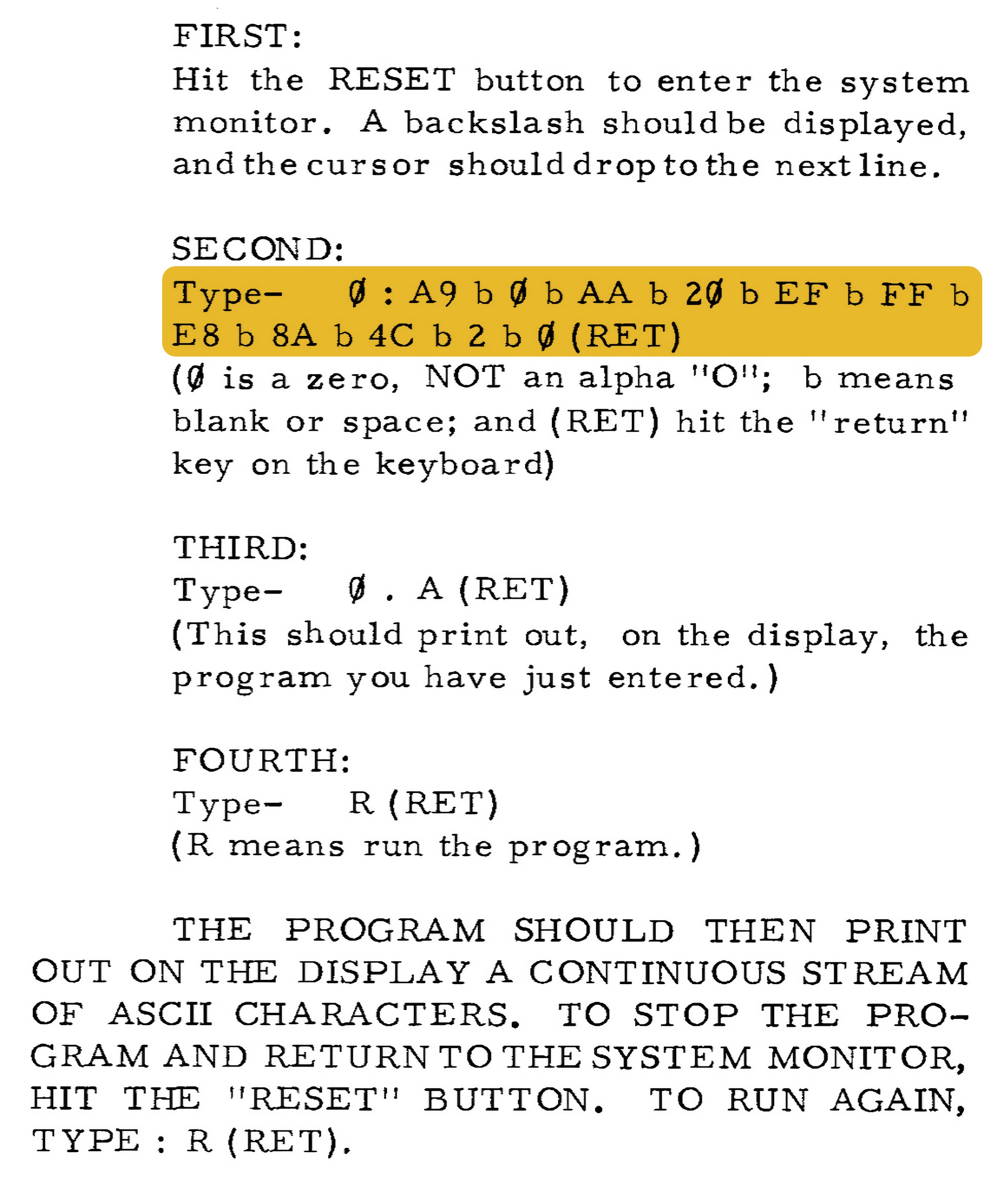
After that, I tried a small memory test shared by Uncle Bernie:
1
2
3
4
5
6
7
8
9
10
11
12
13
14
0280: A9 00 85 00 A8 49 FF A2
: E0 86 01 91 00 C8 D0 FB
: E8 E0 F0 90 F4 49 FF 8D
: 3F E0 8D C0 EF 8D 6A E5
: 8D 95 EA CA D0 F1 88 D0
: EE 49 FF 8D 3F E0 8D C0
: EF 8D 6A E5 8D 95 EA A2
: E0 86 01 D1 00 D0 11 C8
: D0 F9 E8 E0 F0 90 F2 AA
: A9 AE 20 EF FF 8A B0 B5
: 51 00 20 DC FF A9 C0 20
: EF FF 8A 20 DC FF 98 20
: DC FF A9 A0 20 EF FF 4C
: 80 02
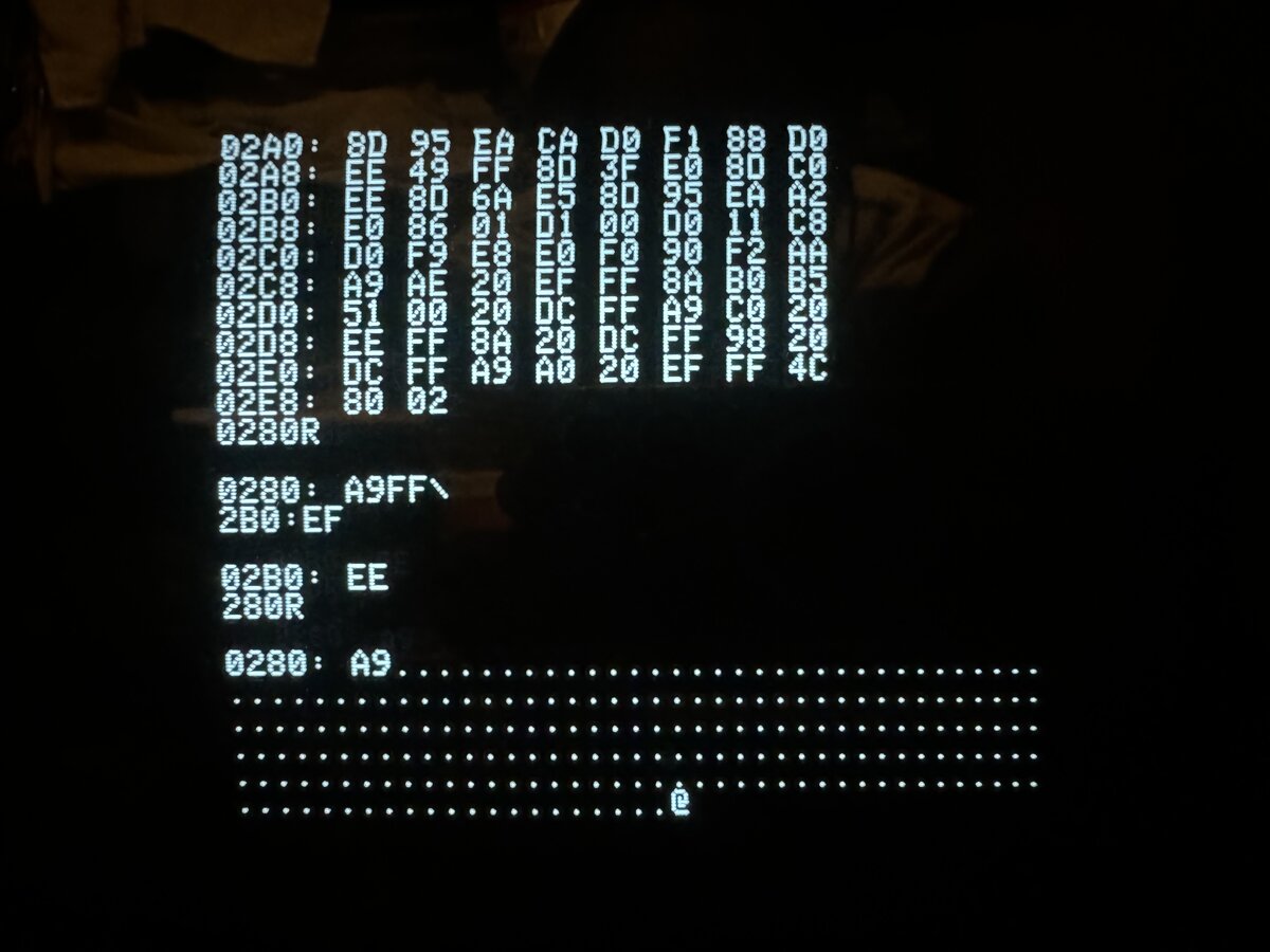
It took me a while to enter it by hand, and it didn’t work the first few times due to typos. But eventually it ran!
EPROM board
It is not fun to enter programs in hex by hand. So I had ordered PCBs for the simple EPROM board designed by Macintosh_nik.
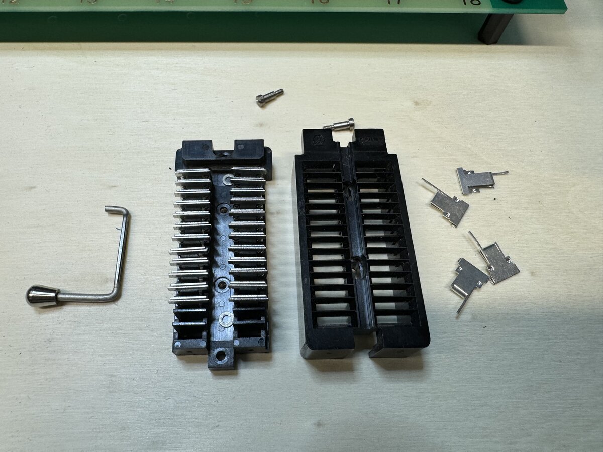
This fits at most a 4 KB EPROM (2732). I assembled it, realized the 2 ZIF sockets I had had 28 pins while the PCB fits a 24-pin socket only! I opened up one of the ZIF socket, as I realized I could remove extra pins from it, but then realized that it was not necessary as I could solder a 24-pin machined socket, then plug the ZIF socket in!
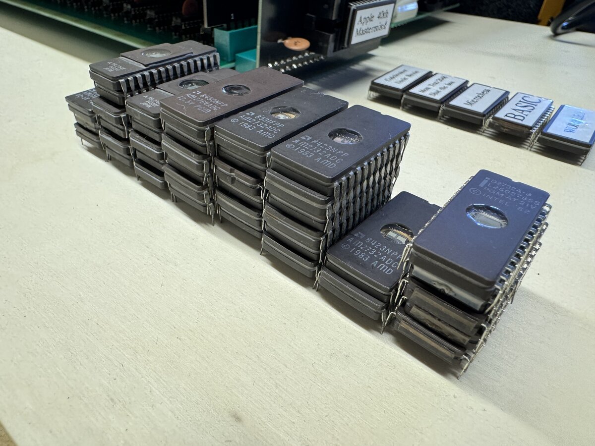
I made some address decoder wiring changes, so that my EPROM could be at location E000-EFFF, which is the regular location for BASIC, in particular. I have a stack of EPROMs:
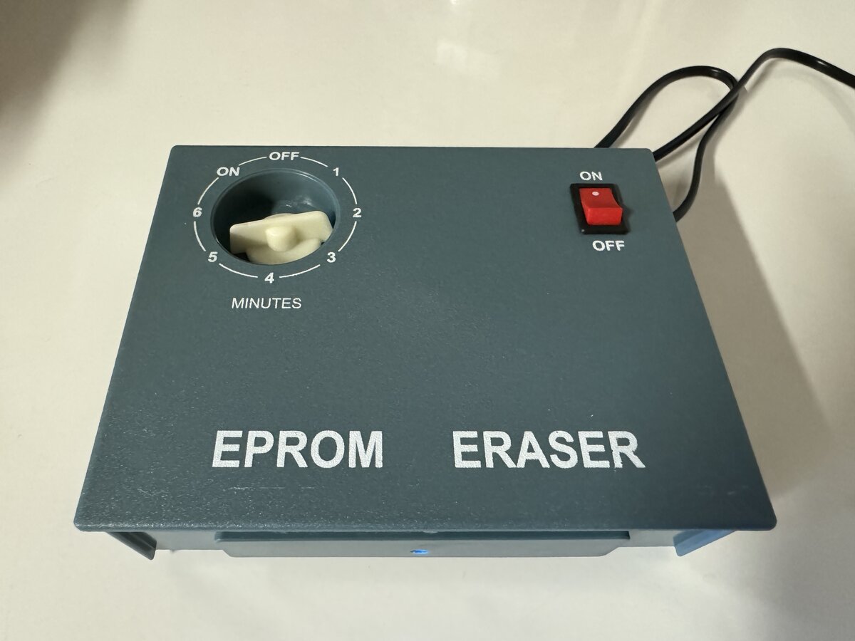
I did try to read all EPROMs before erasing them, but I doubt there was anything valuable on them. Here is the cheap EPROM eraser I used:
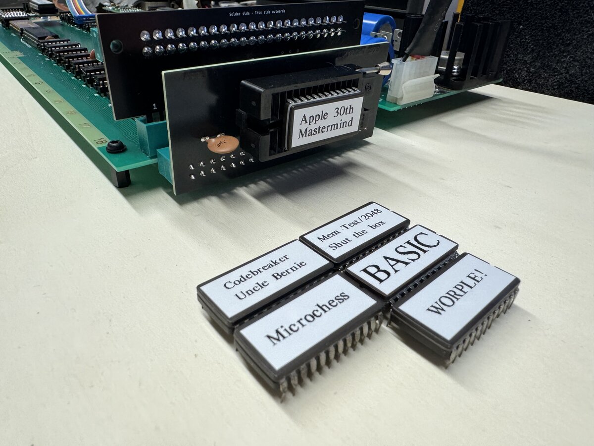
I programmed some EPROMs with binaries provided in online forums, including:
- BASIC
- WORPLE!
- Apple 30th/Mastermind
- Memory test/2048/Shut the box
- Codebreaker
- Microchess
I hit a snag where things didn’t work perfectly, then realized I had incorrectly reassembled the ZIF socket. Another mistake was to put the EPROM the wrong way around. Luckily, nothing bad happened to either the EPROM or the board! Here are some EPROMs I programmed and the EPROM board:
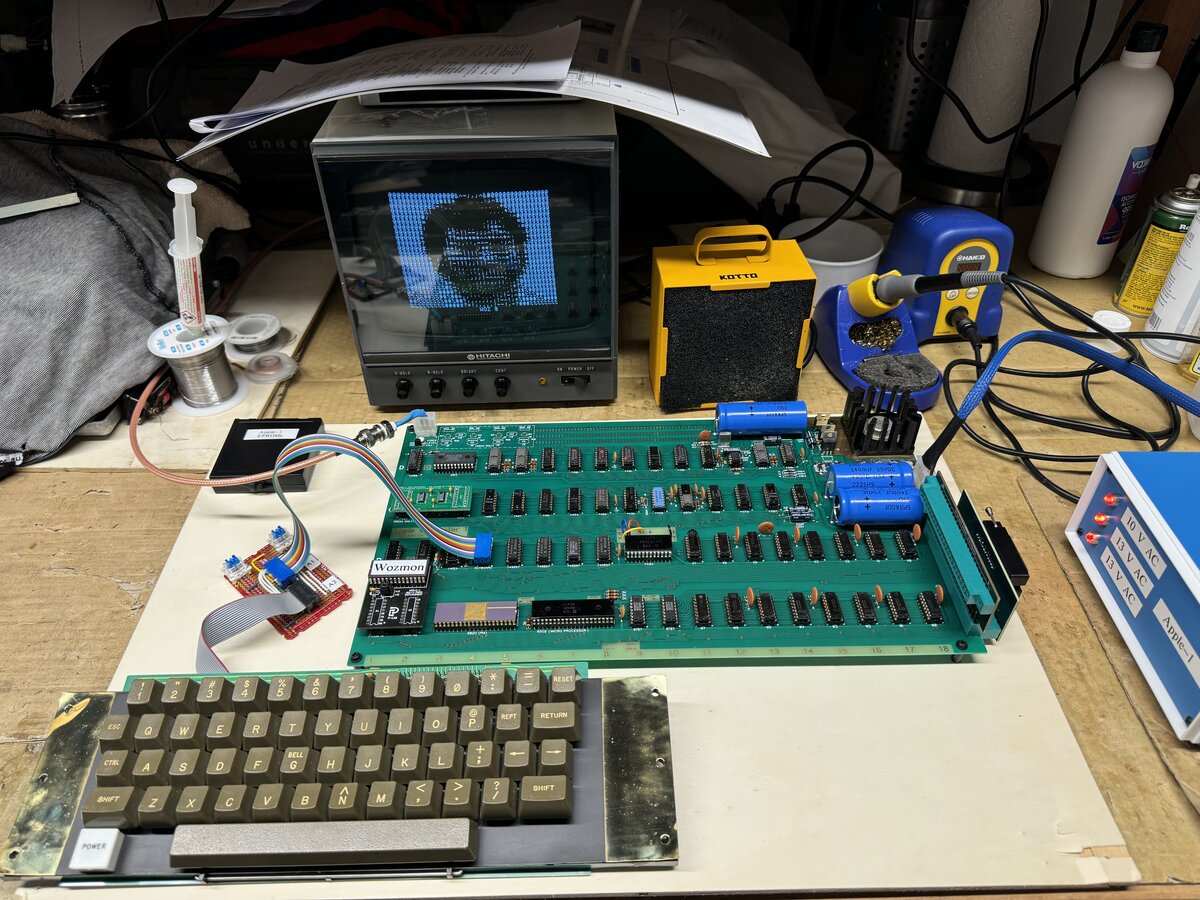
It is fun to play the 30th anniversary demo, which shows a series of pictures including Woz, Steve, and newer Apple products, all in ASCII art. Here is Woz on screen.
Video fix
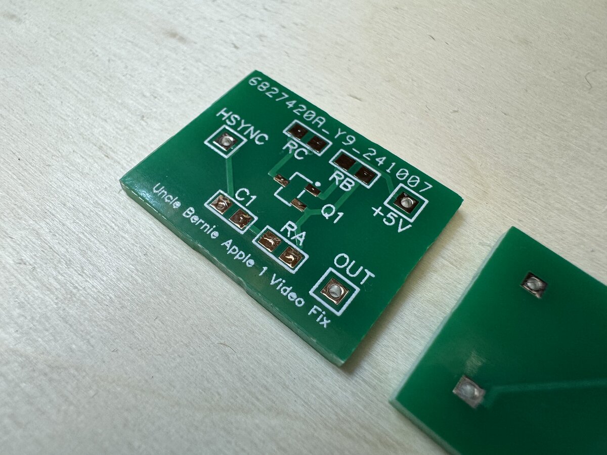
The Apple-1 video is notoriously not great, because the NTSC signal is not up to spec. Uncle Bernie has a fix, which involves soldering a transistor and a few other components. I figured that I would design a small PCB for this. In fact, this was my first PCB design in decades! I designed it with EasyEDA and ordered boards from JLCPCB. I used:
- 805-size SMT capacitors and resistors
- SOT-23 BC858CL transistor
Here is the tiny resulting PCB:
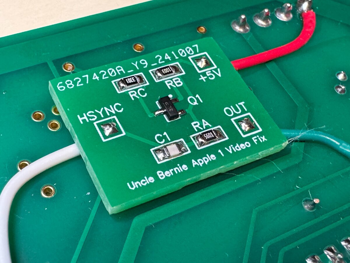
Here is the PCB populated and attached with double-sided tape to the back of the main board, and how it makes for a neat solution:
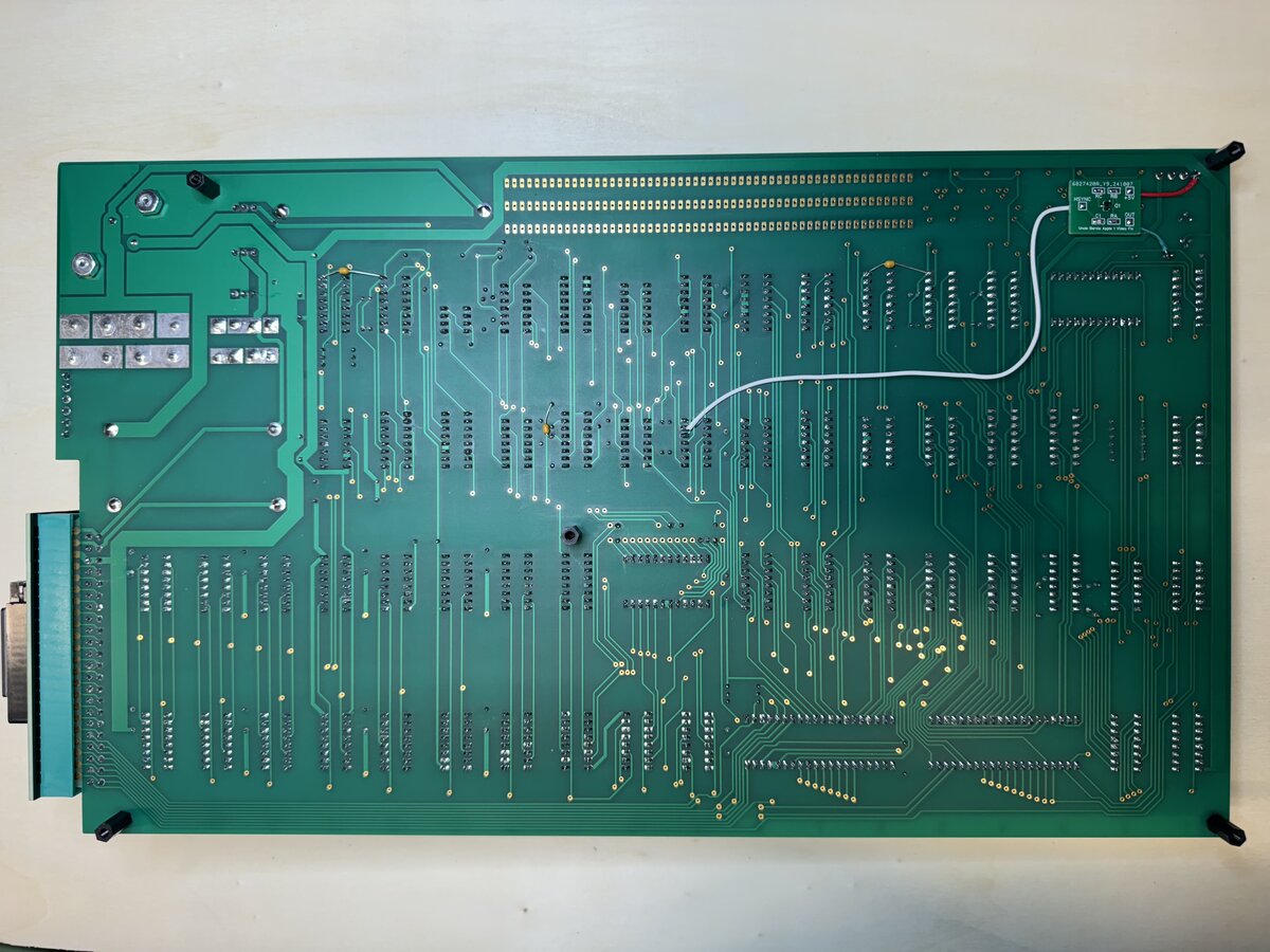
You can see how tiny the PCB is compared to the main board:
I was happy to see that indeed, the fix worked, in that it centered the image much better on the monitor:
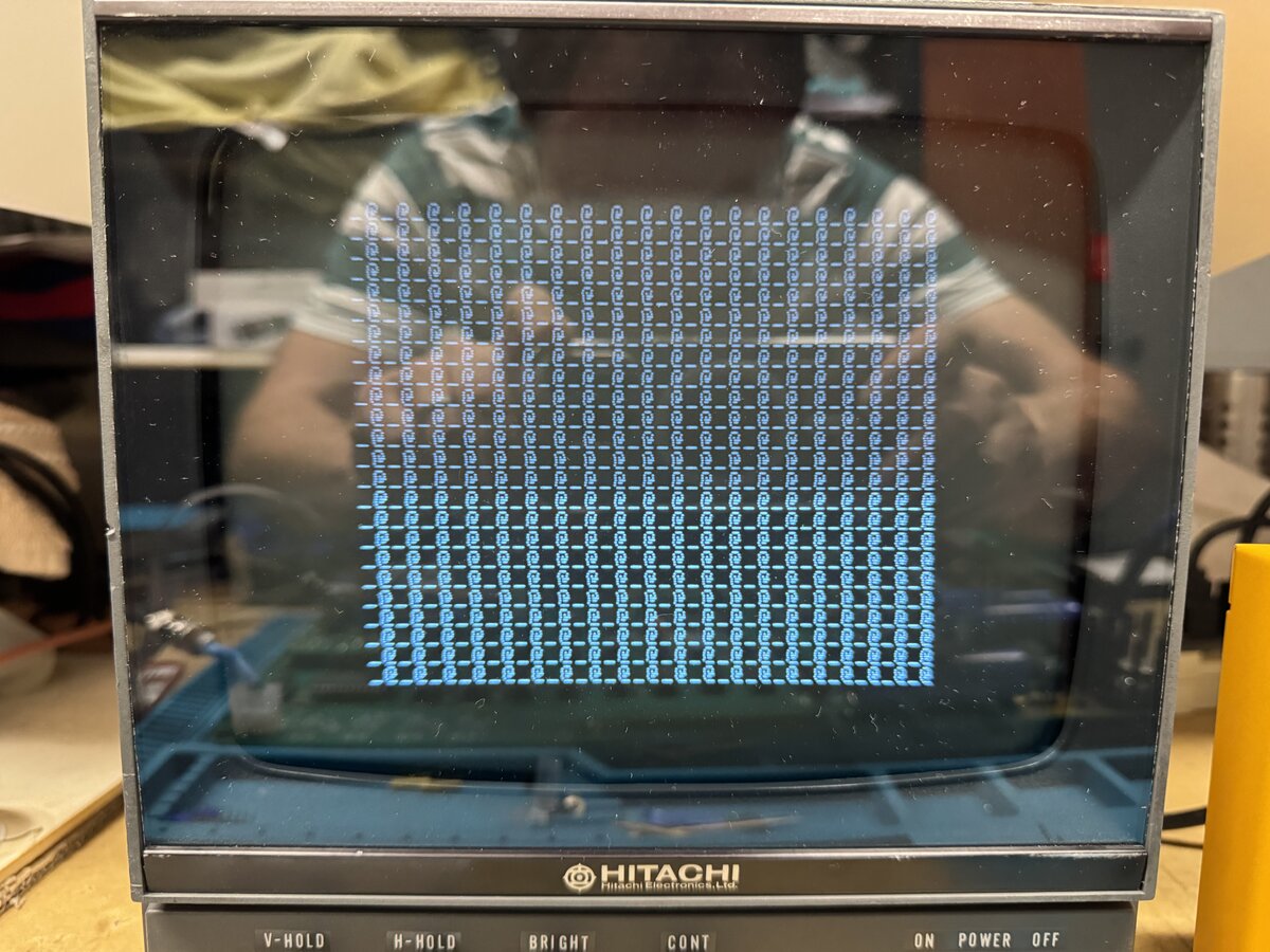
Unfortunately, there was a problem: in some cases, especially when scrolling a lot of text on screen, the image wobbles. This is quite visible on the left side. This was also visible with the LCD monitor, although you can’t tell based on a picture:
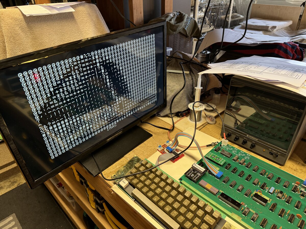
I tried to change the values of the components, in particular the capacitor. Using 33 pF was not worse, but using 220 pF was definitely worse! Either way the wobble remained. I tried a 75 KΩ resistor instead of 100 KΩ, but there was no visible difference. At this point, I gave up fixing this, at least temporarily. I still don’t know if this is due to the design of the fix, the transistor I chose, my PCB layout, wires, or something else. I left the fix in, as it is ok, but not perfect. It is easy to disconnect it.
2519 replacement variant
I used the 2519 replacement board designed by Szillat and P-LAB. This worked great, but I had the issue that the small-package 14557 shift registers are not available from major electronics components stores (or only in very large quantities). I had to buy those on eBay, and they are not reliably available there either. However, the SOIC-16 Wide chips are easily available (mouser, DigiKey). So I recently I redesigned the board to handle the larger chips. I managed to do this without making the board larger, partly by putting all the decoupling capacitors on the opposite side. I made it black to keep with my “black replacement board” theme.
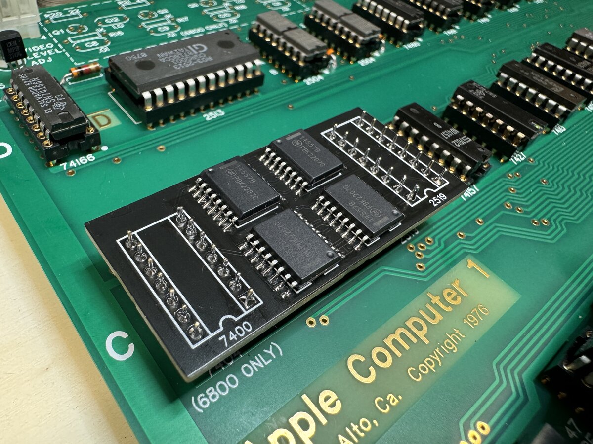
View from the top:
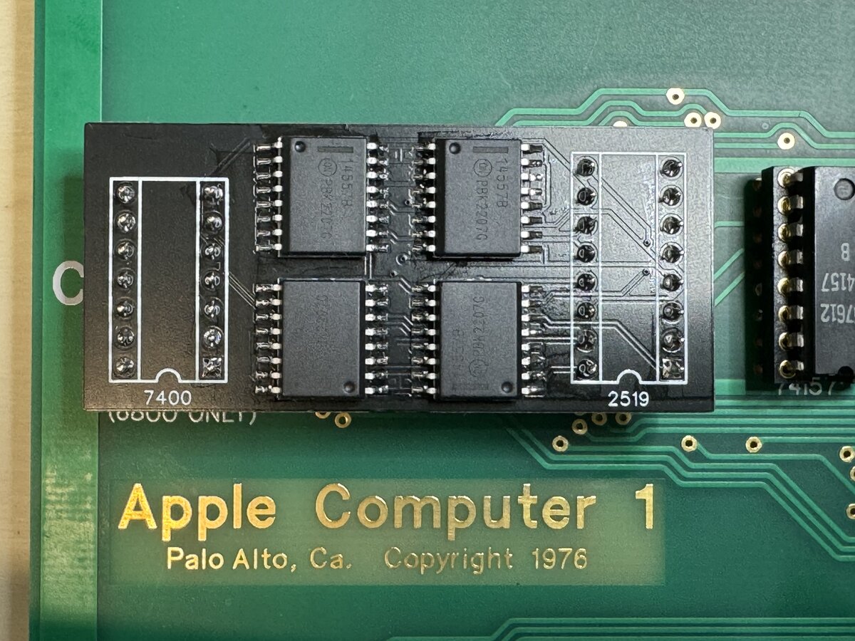
Here is a close-up of the chips on the new board:
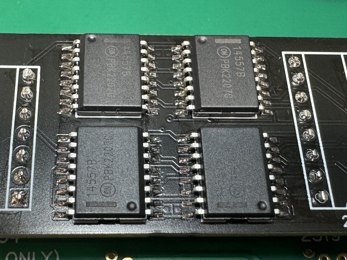
Compare with the original version:
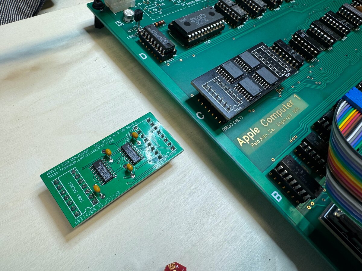
The project is available on GitHub.
Here is the outline of the board:
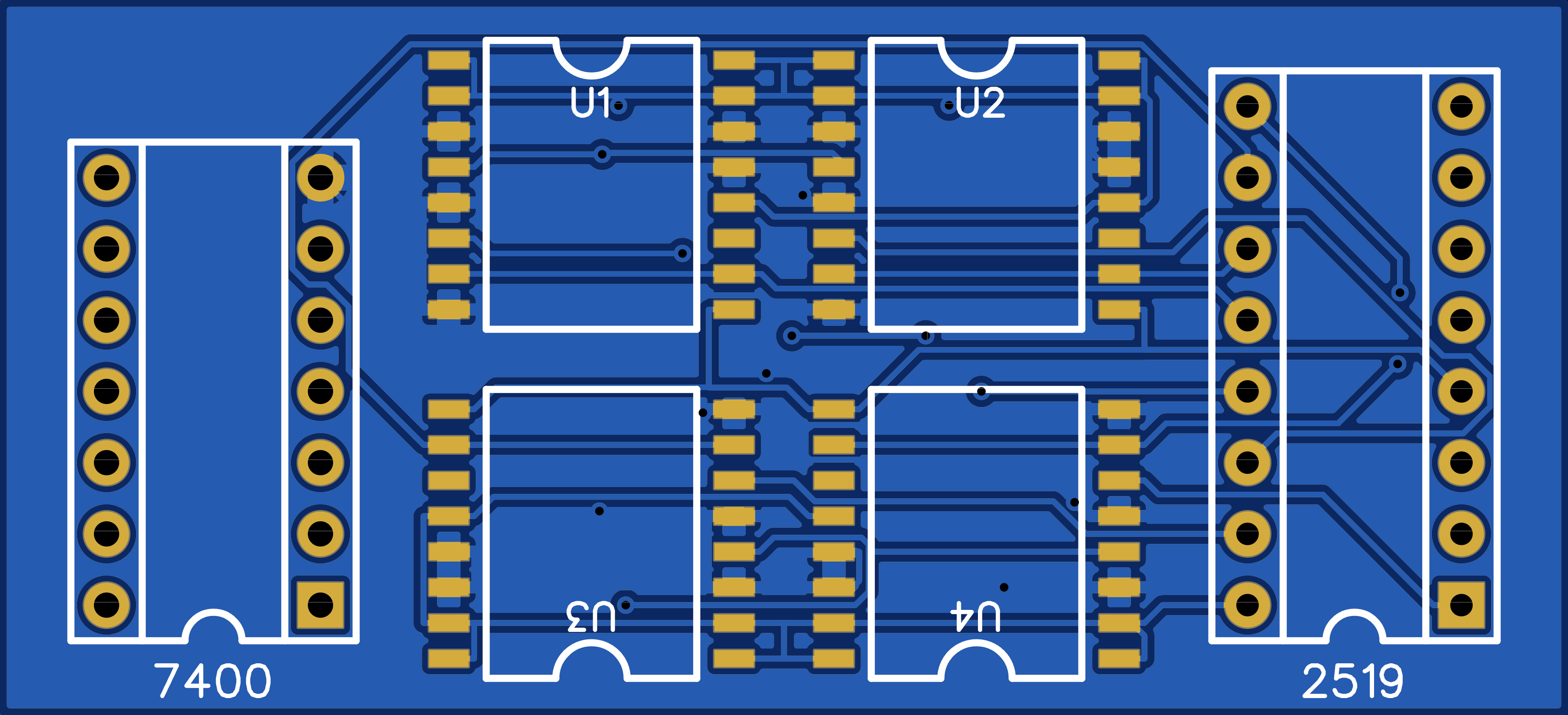
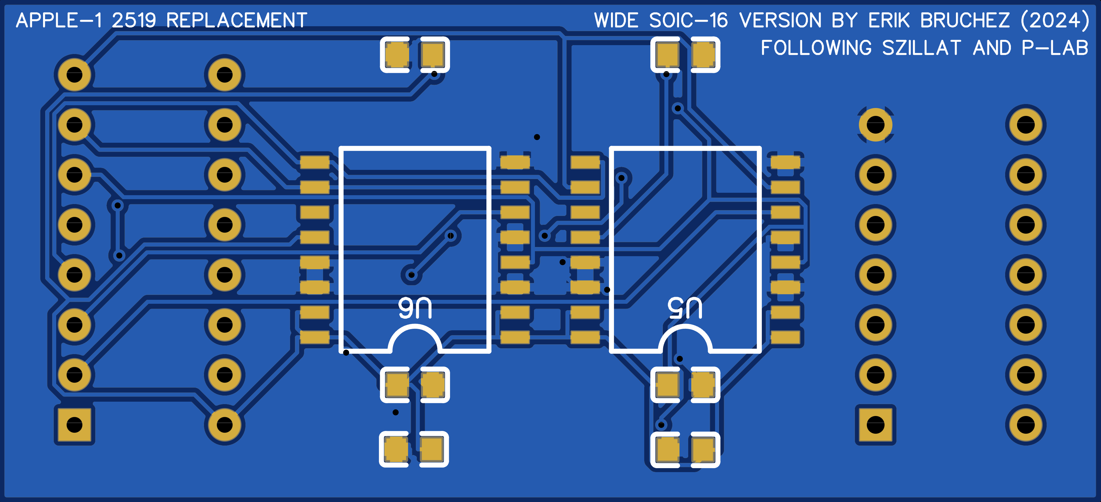
I was kindly pointed out by P-LAB that there were some small issues with my PCB, including missing vias and traces that are too narrow. I fixed those in EasyEDA, but haven’t yet ordered new PCBs. This said, the current one works!
PROMs
I had omitted buying PROMs for WOZMON, as I couldn’t find blanks and I was not sure I could program them myself easily anyway. So I had used that EPROM daughter board, which works really well.
But incredibly, I got offered a set of free PROMs from an Apple-1 community member, shipped all the way from Germany! I am very grateful for this kind gesture. Here they are:
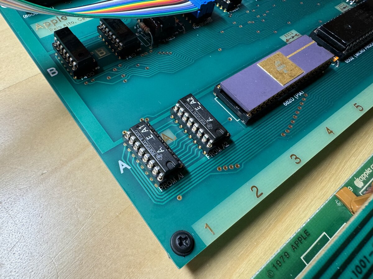
Conclusion of part 5
This part covered some of the most exciting aspects of the project, and it ended with a well-working Apple-1 reproduction!
As usual, you will find more pictures in this photo album:
Part 6 covers programming the Apple-1 in C.

Comments powered by Disqus.