
This is part of a series of posts about building an Apple-1 reproduction in 2024 (and 2025). See also:
- Building an Apple-1 Reproduction in 2024 - Part 1: Components
- Building an Apple-1 Reproduction in 2024 - Part 2: Power Supply
- Building an Apple-1 Reproduction in 2024 - Part 3: The Retro Chip Tester
- Building an Apple-1 Reproduction in 2024 - Part 4: Assembly
- Building an Apple-1 Reproduction in 2024 - Part 5: Monitor, Keyboard, Power-Up
- Building an Apple-1 Reproduction in 2024/2025 - Part 6: C Programming
Introduction
The Apple-1 was very short-lived and made in small quantities (less than 200 units). Unlike other computers of the days, it never got to have many peripherals. However, Steve Wozniak did design an audio cassette adapter (known simply as the “ACI”), which allowed the Apple-1 to save and load programs and data to and from standard audio cassettes. This was the Apple-1’s “storage” in modern parlance — that is, some kind of persistent memory.
The idea of using an audio recorder to keep computer data is simple: you encode each bit of data as a short sound. Specifically, in this case, according to the ACI manual:
a 1 kHz cycle (representing a ‘one’ data bit) or a 2 kHz cycle (representing a ‘zero’ data bit)
It’s a miracle that something this simple worked, especially with an electronic circuit containing only four chips in addition to the PROMs. But it did, with some caveats about reliability.
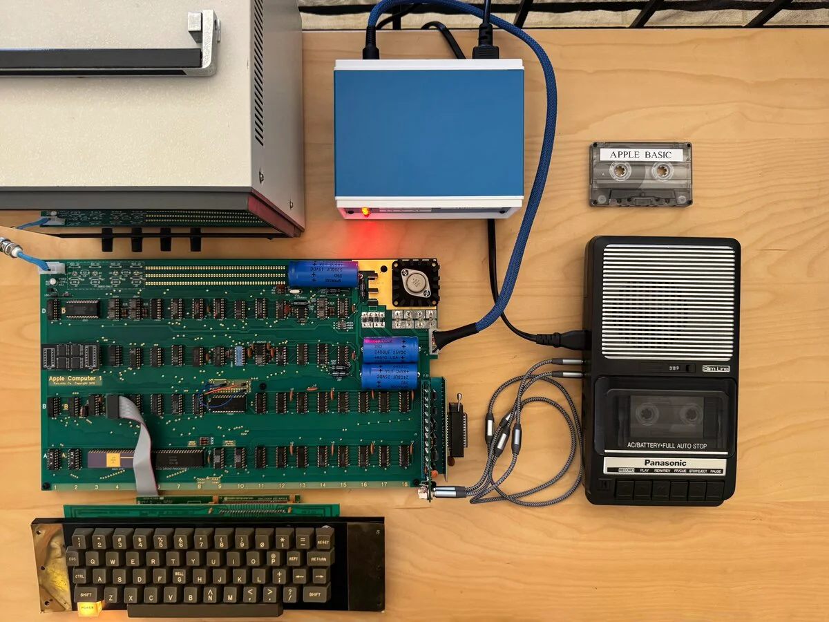
The ACI fits into the single expansion slot of the Apple-1. This still leaves the edge connector available for other extensions, but it is a reminder that the Apple-1 had relatively few extension capabilities by default, in particular compared to the later Apple II, which had eight expansion slots.
The PCB
I ordered the PCB from Mike Newton (AKA Mike Ng). It wasn’t as cheap as if I had one made directly from a PCB manufacturer, but it looks closer to the original. In fact, it is a beautiful PCB.
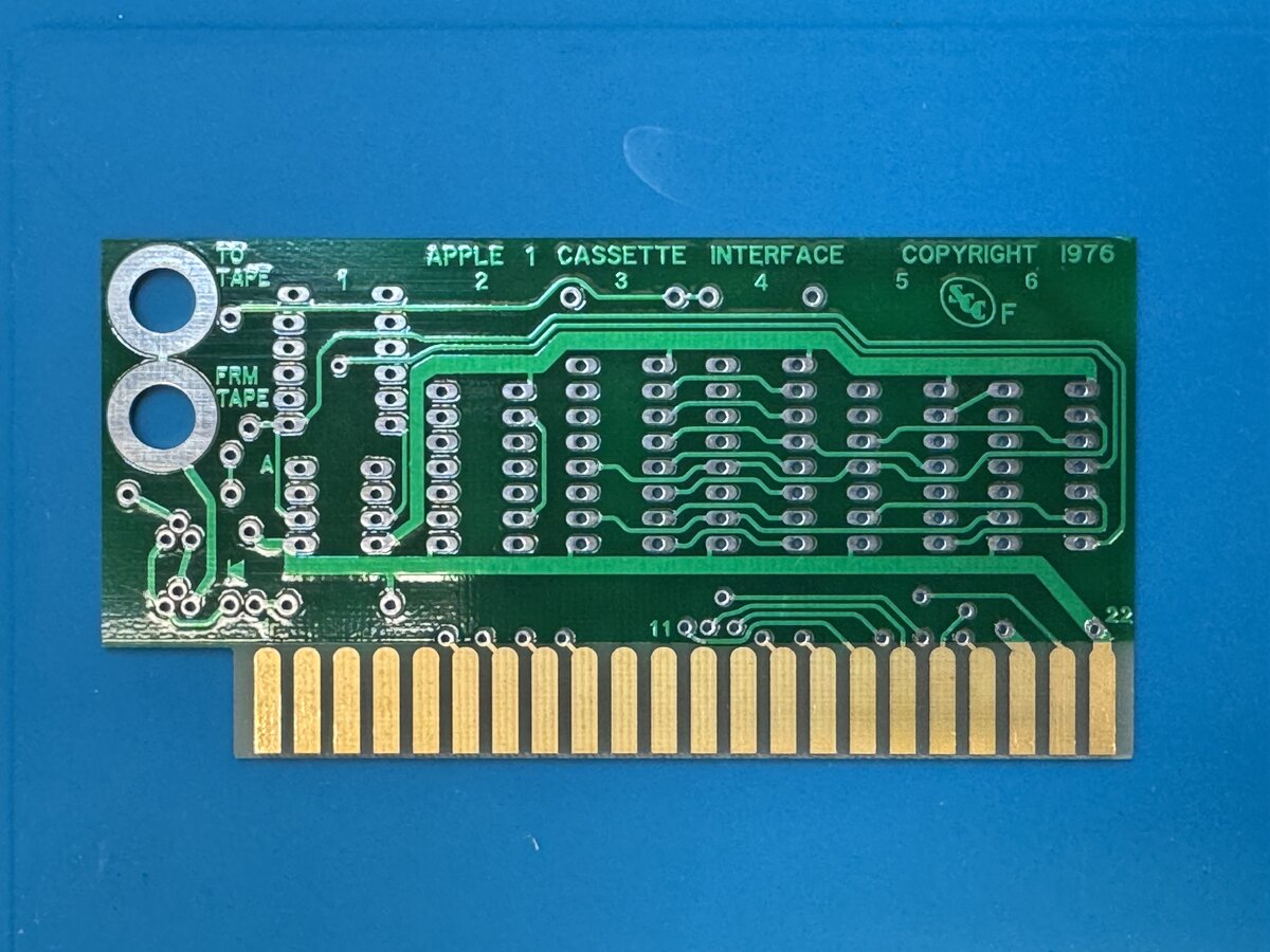
The PCB came not only with programmed PROMs, but also with a few spare components.
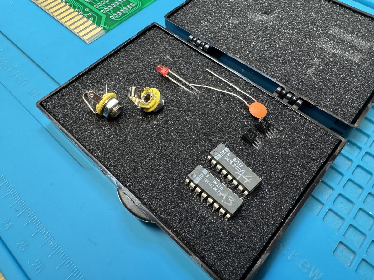
I happened to already have most of the components, but I appreciated them anyway.
Components
I had already acquired most of the components for the ACI while I was planning the acquisition of the components for the main board. There is not that much:
| Component | Comment |
|---|---|
| PROMs | I had two sets, one from Mike and one from Germany. |
| IC sockets | I used machined sockets, as I did for the Apple-1 main board. |
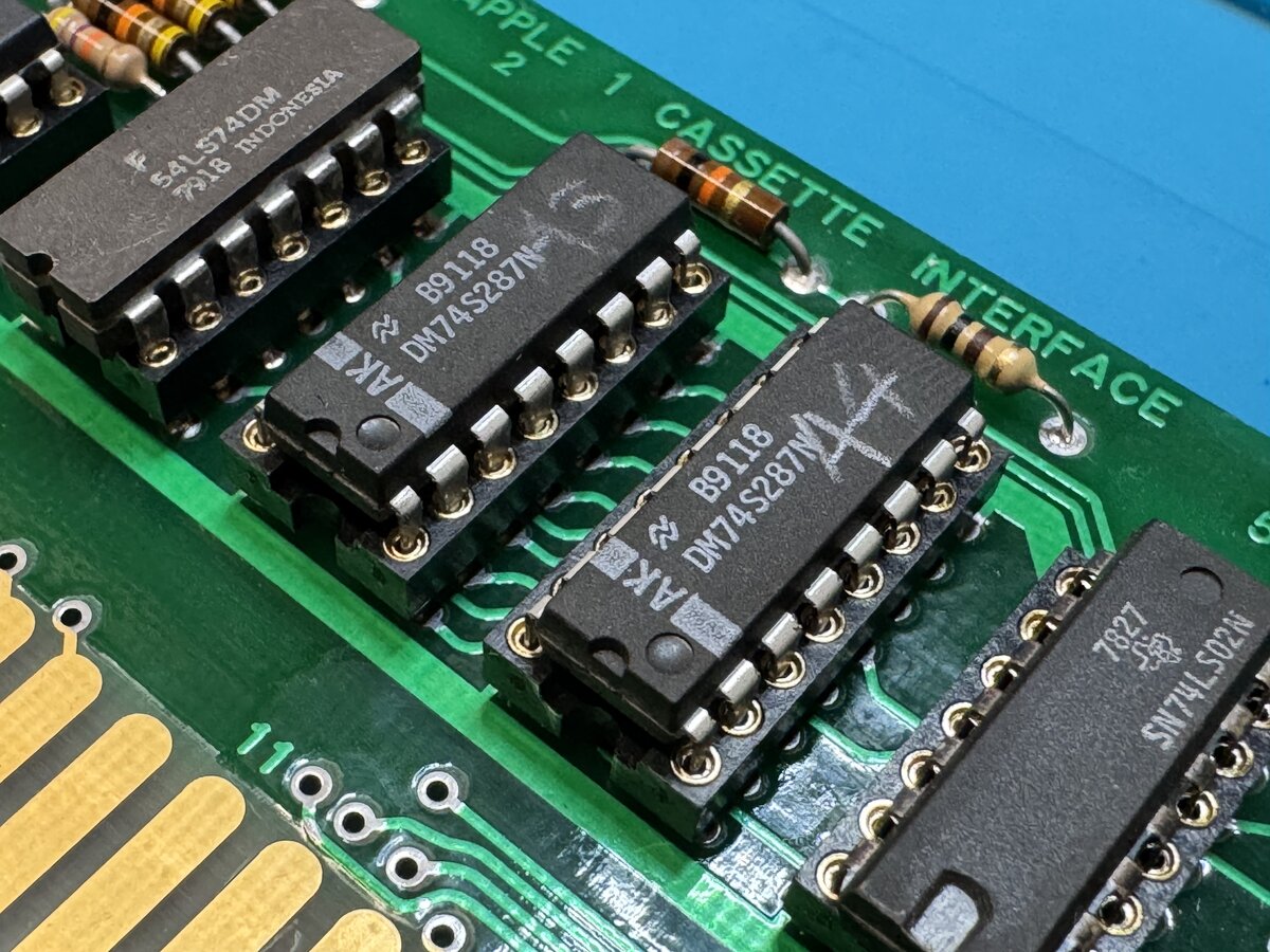
| 74 series chips | Unlike those on the main board, these are “LS”. |
| LM311 op amp | |
| 2 transistors | The 2N3904 is a proven modern replacement for MPS3704. |
| LED | I went with the 3 mm size instead of the 5 mm. I believe that the 3 mm size is more correct. |
| Resistors | See further notes below about the 10 kΩ. I tried to get Allen Bradley resistors when possible, for looks. |
| Capacitors | One is needed for the original design, and one more for the volume indicator mod. |
| Audio jacks | You can still buy the panel-mount audio jacks new, which I had done already, in addition to those I got from Mike. |
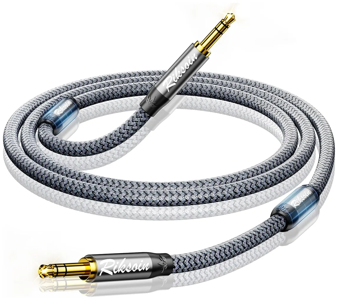
| Audio cables | I wanted to have some good-looking, flexible, short audio cables. So I ordered 2 feet long braided cables from Amazon, with 3.5 mm male jacks on both ends. |
ACI options
Resources
You might think that things are simple: get the PCB, components, solder, and voilà. However, there is more to it. Here are some resources that I consulted before proceeding with the build:
- Mike Willegal’s Mimeo Cassette Interface Assembly and Operations Guide
- On AppleFritter:
- San Bergmans’s page about the Apple-1 Cassette Interface
Input capacitor
Everybody agrees that a specific change needs to be made compared with the original. This recommendation was made by Mike Willegal’s in particular. It consists in increasing the value of the input coupling capacitor from 10 nF to 100 nF. The 10 nF value just seems to have been a bad design choice back in the days:
- Mike Willegal: “increase the value of the input coupling capacitor”
- Uncle Bernie: “It is absolutely necessary that you put the 100nF input capacitor mod in, as suggested by Mike Willegal.”
Decoupling capacitors
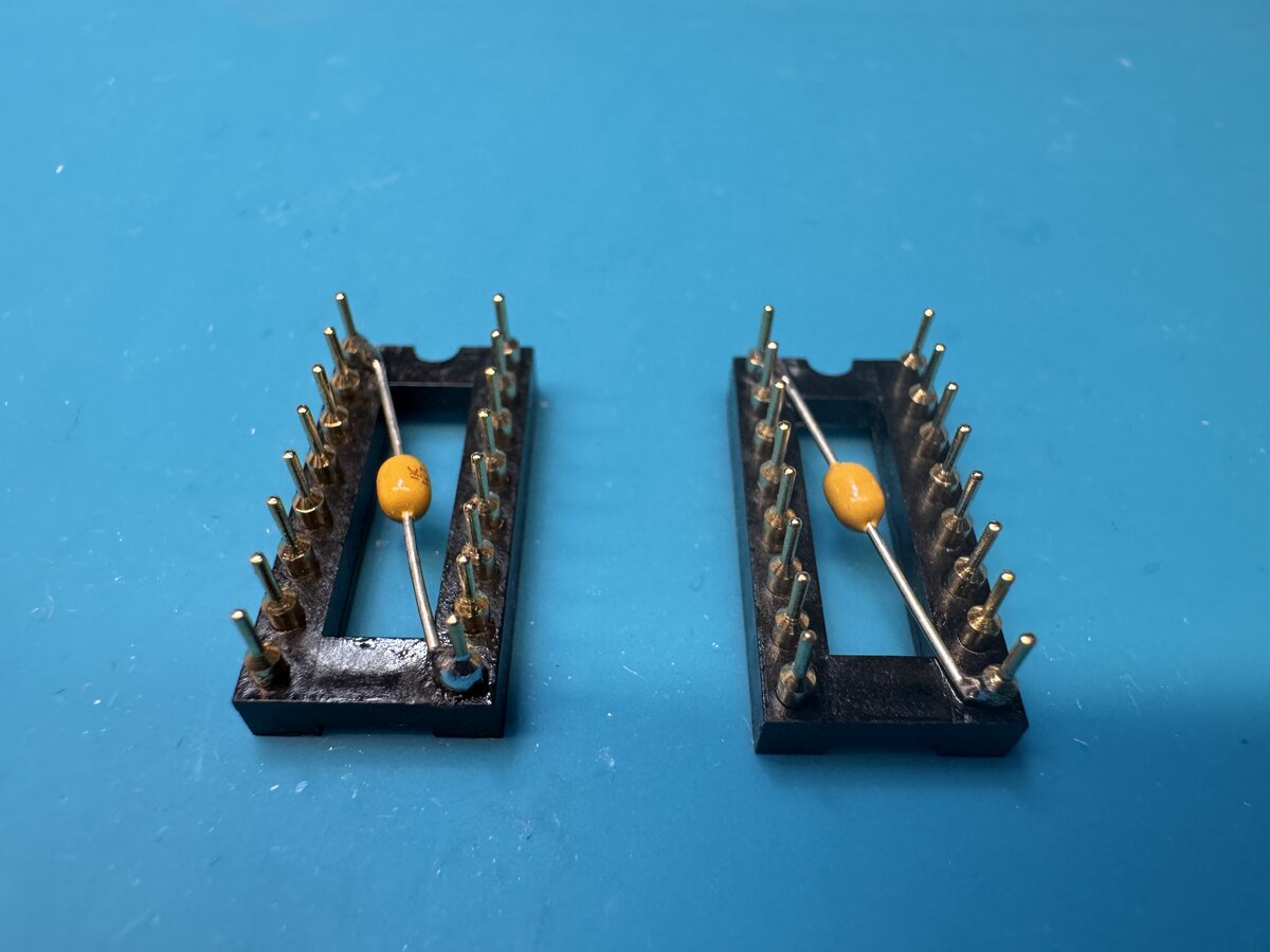
This might be minor, but I decided to add two decoupling capacitors for the PROMs. This is not strictly necessary, but it won’t hurt, and I am now confident about mounting capacitors into IC sockets.
10 kΩ resistors
The original ACI called for 1% 10 kΩ resistors. But Uncle Bernie commented:
The 1% spec probably was an attempt by Woz to make the ACI work better. The attempt failed. No amount of matching in these resistors can undo the catastrophic AC impedance mismatch which suddenly occurs at the comparator inputs when the cassette recorder is plugged in.
And:
But according to my opinion, it is not necessary to use 1% tolerated resistors for the four 10K ones. You can use 5% and 10% resistors (which I tried out). With 20% resistors (old carbon composition resistors perhaps) I’d recommend you to measure a bunch of them and pick four which come closest to each other. This “closeness” of the values among these four resistors (electronic professionals call this “matching”) most likely is the reason why Woz specified 1% tolerances.
So I just used my large batch of Allen Bradley 10 kΩ resistors. I measured a few and picked four that were close, understanding that this was probably not necessary, but there was no real drawback going through this just in case.
Gen1 or Gen2?
Uncle Bernie worked on an improved version of the ACI, which he calls “Gen2.” I looked into it, but unfortunately PCBs for it are not in the open and not available anymore from Mike Newton. So I decided to go with the “Gen1” version, which is the original version, but with some improvements.
Uncle Bernie suggested two types of ACI improvements:
- A fix for the volume indicator, which uses the unused half of the 74LS74.
- The use of larger PROMs, with improved software.
I decided to implement the first one, but not the second one, as I don’t have the larger PROMs anyway.
The audio volume fix requires cutting two traces on the ACI board, and adding some wires as well as a capacitor. Uncle Bernie suggested mounting that capacitor within an IC socket, but since the wire needs to go out, it is a little tricky. I decided to leave the IC socket unmodified, and to place the capacitor on the bottom of the board. I carefully bent the legs of the capacitor, and used heat shrink tubing to protect the legs and wires. This is more visible than Uncle Bernie’s solution, but a little less tricky to implement. However, I am pretty happy with how the small wires to the jacks came up!
In summary, compared to the original ACI, the list of changes is as follows:
- use the 100 nF input coupling capacitor mod
- add two decoupling capacitors for the PROMs
- for the volume indicator fix
- cut two traces on the ACI board
- replace the 100 kΩ resistor with a 5.1 MΩ resistor
- add the 1 nF capacitor
- add the necessary wires
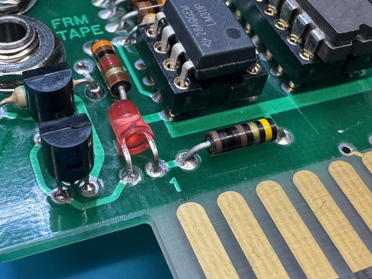
I didn’t have Allen Bradley resistors except for the 10 kΩ ones, so I used regular resistors, which I soldered a little more lightly so I could replace them later. In fact, I quickly got and soldered Allen Bradley 100 Ω resistors.
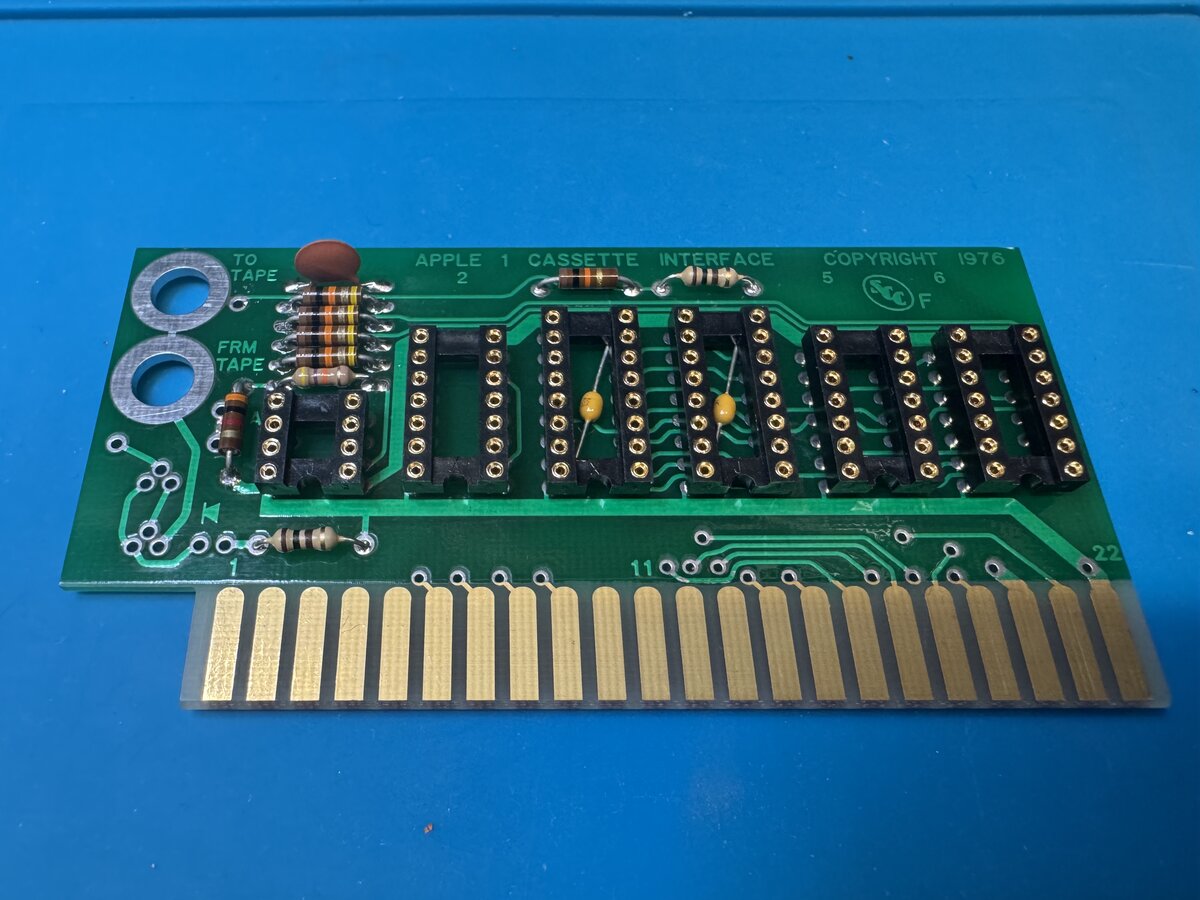
Here is the fully assembled ACI board without the ICs.
Note that I mounted the 3 mm LED bent, as I think most ACIs were made.
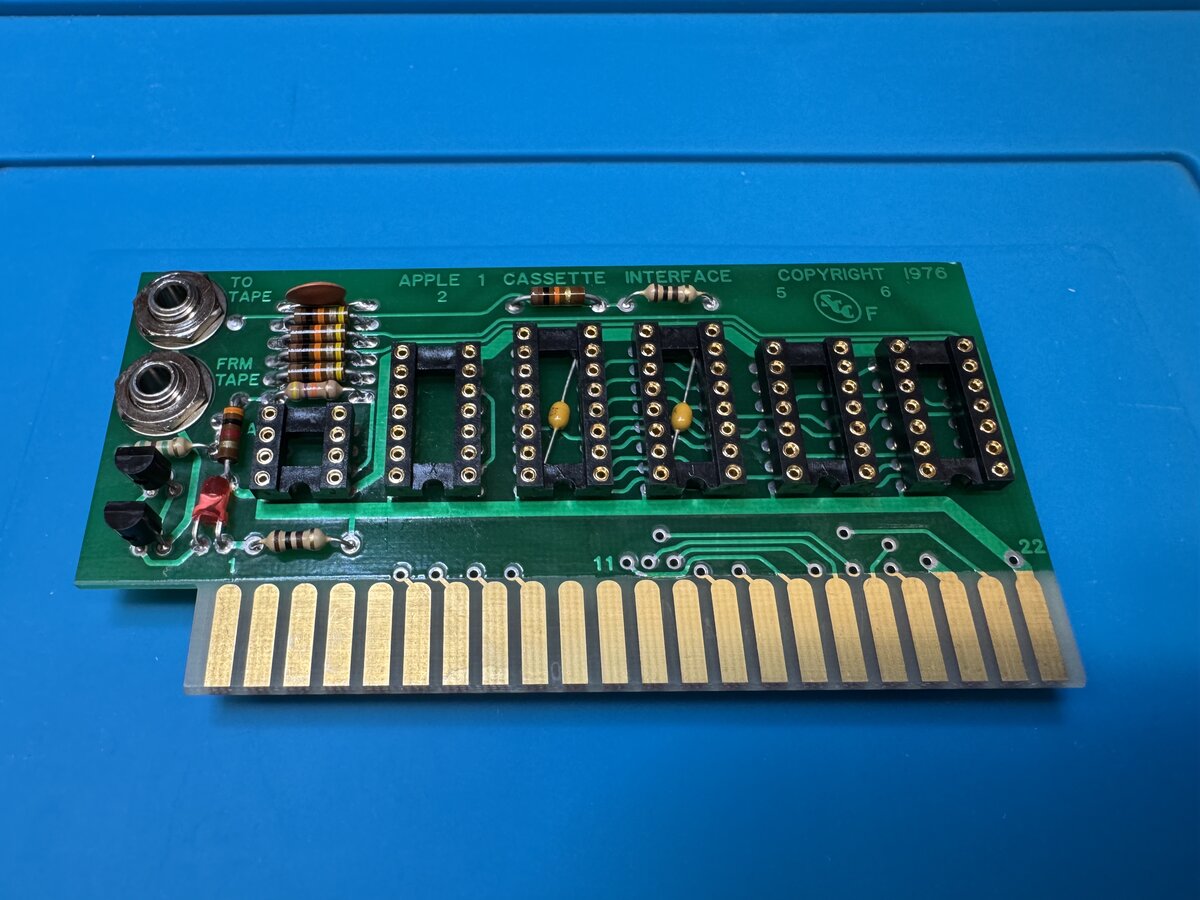
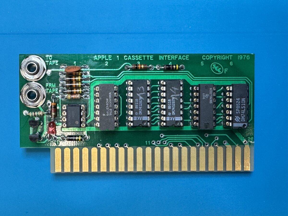
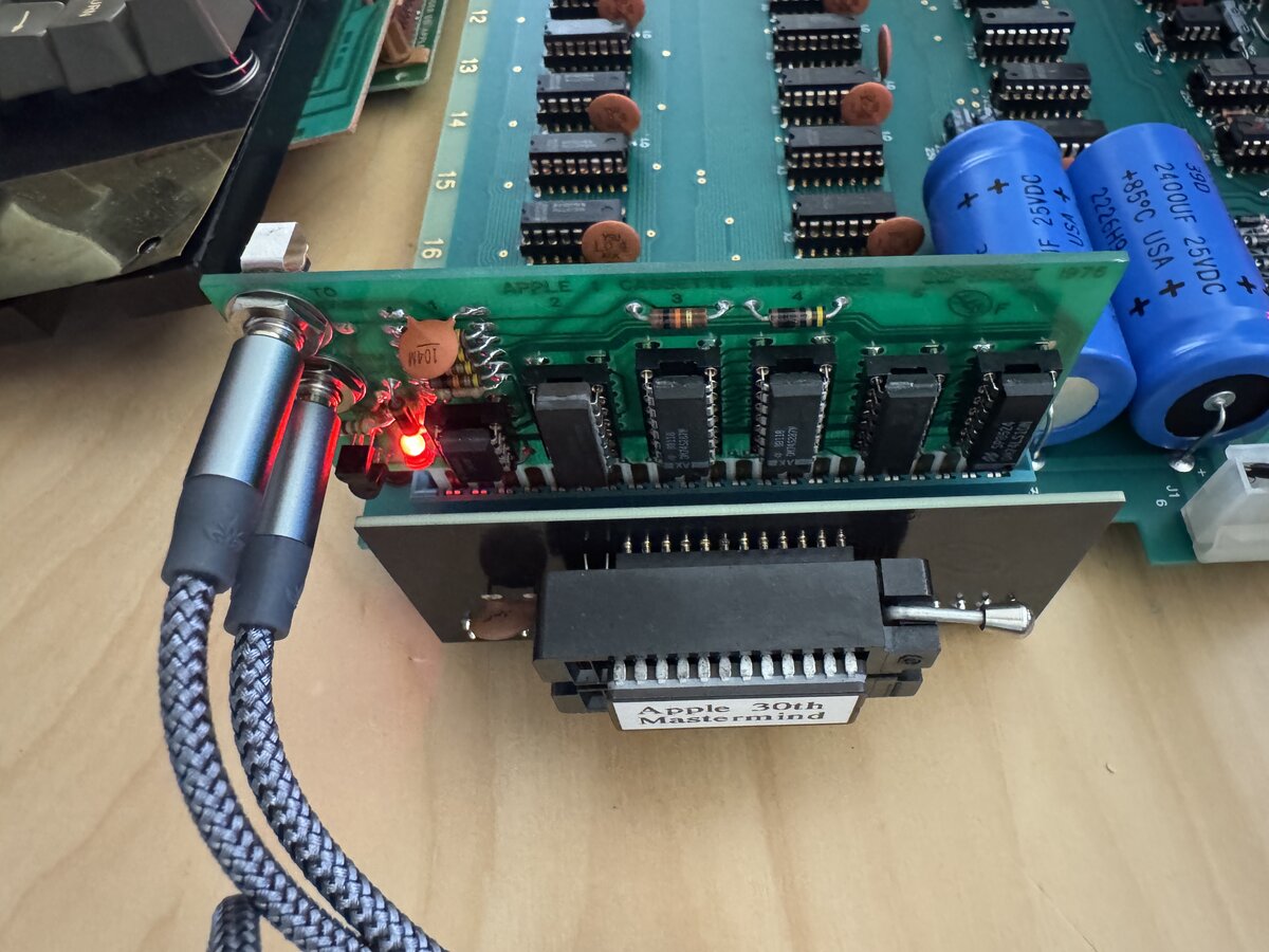
And here is the fully assembled board with the ICs mounted in their sockets.
Installing the ACI
The first thing to be careful about here is the orientation, facing outward.
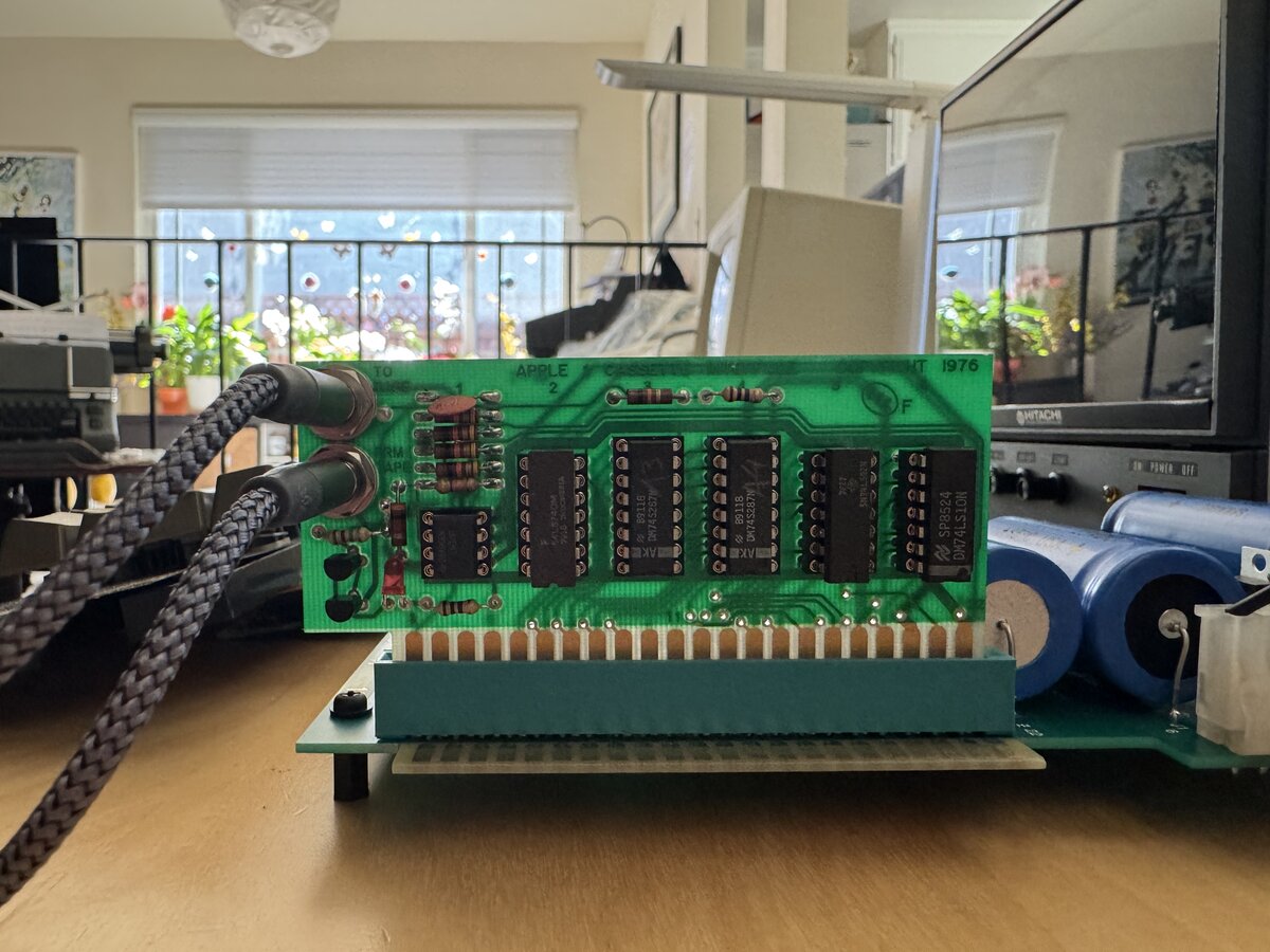
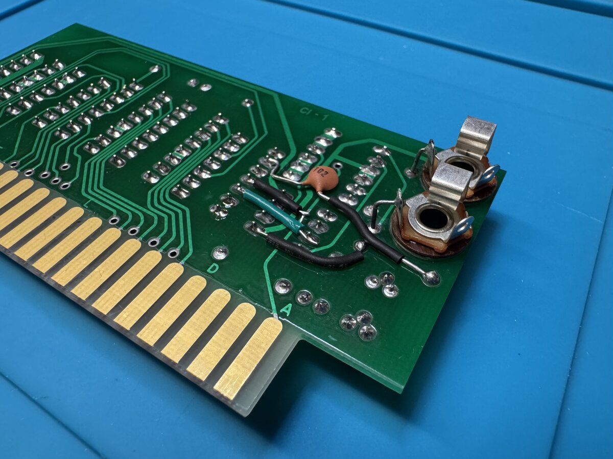
Here is the view from the other side. The mods are definitely visible, and there is surely a way to make them a little less conspicuous, but I don’t think that it’s a big deal. Remember that the Apple-1 was a hobbyist’s computer, designed to be modded and tinkered with.

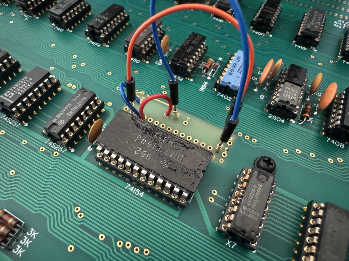
I had to update my memory map: I had set E000 to map to the EPROM, in order to have contiguous RAM in 0000-1FFF for my C code. So installed individual machined IC socket pins in the memory map section, so I could easily jumper them. It worked, although I am slightly concerned about the reliability of the jumper wires.
Testing the ACI
The ACI had its own software implemented into two PROMs on the board itself.
Those are simply mounted in the Apple-1’s address space at address C100. You run the ACI program from that address from Wozmon with:
1
C100R
The ACI program lets you read or write memory ranges from and to tape, using a slightly cryptic syntax similar to the Wozmon syntax for examining memory. Running this worked the first time, showing a * prompt: my soldering and the PROMs were good!
The most significant program written for the Apple-1 was probably Woz’s Integer BASIC, so it was natural to load that first. I had already run it from EPROM, so I knew it worked. But now I wanted to load it through the ACI.
Since I didn’t have a tape recorder at first, I connected the input audio cable to my laptop’s audio output. I played back the Apple-1 audio from the Internet Archive from my computer.
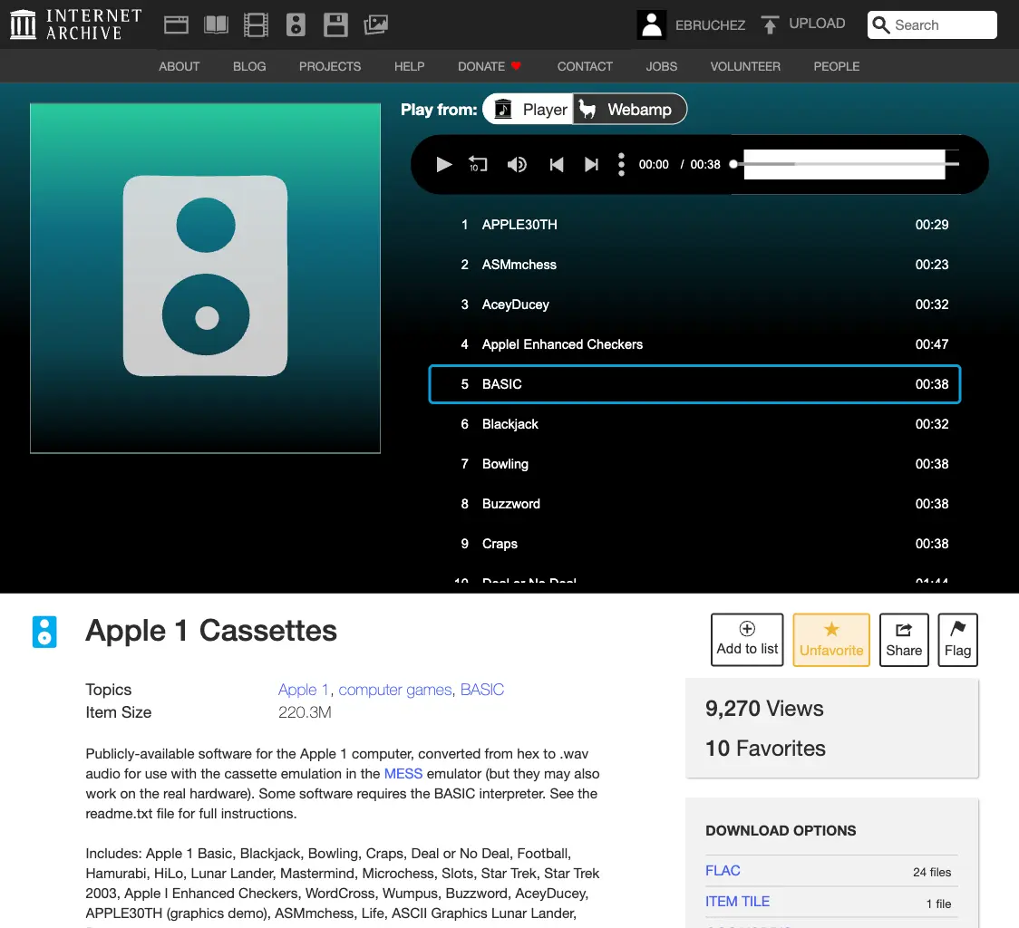
The volume indicator didn’t light up at first, so I checked the connections and found that I had forgotten to solder a pin of the 74LS74! I fixed that, and the indicator worked!
I played back the BASIC source from my computer, from archive.org. I used the following command:
1
2
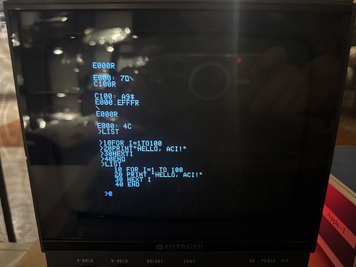
C100R
E000.EFFFR
This reads 4KB form the audio and writes it at address E000. The trailing R means “read,” and E000.EFFFR means “memory from E000 to EFFF.”
At first, it didn’t quite work and running the resulting code at E000R crashed. I reset the computer, started again, but increased the computer’s audio volume a little, and then it worked! This also translated into the indicator LED being brighter and flickering less. I was in BASIC!
The tape recorder
It’s nice and all to be able to use a computer as an audio recorder, but not quite period-correct. So I decided to use a real tape recorder. Apple recommended a Panasonic recorder. Mike Willegal says it was a Panasonic RQ2102 and, “believe it or not, they are still available from Panasonic.” I am not sure they are actually still made in 2025, but I bought a used one on ShopGoodwill, for just over $20 shipped.
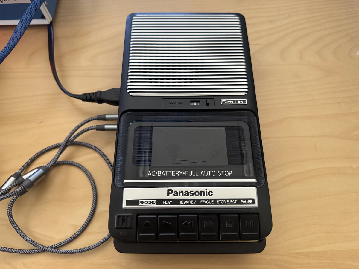
It turned out to be in clean and almost pristine condition.
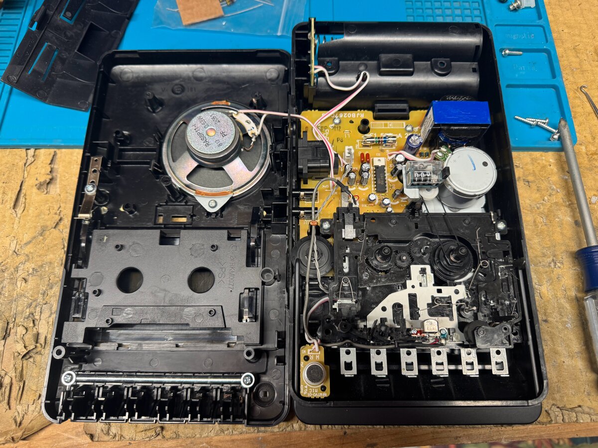
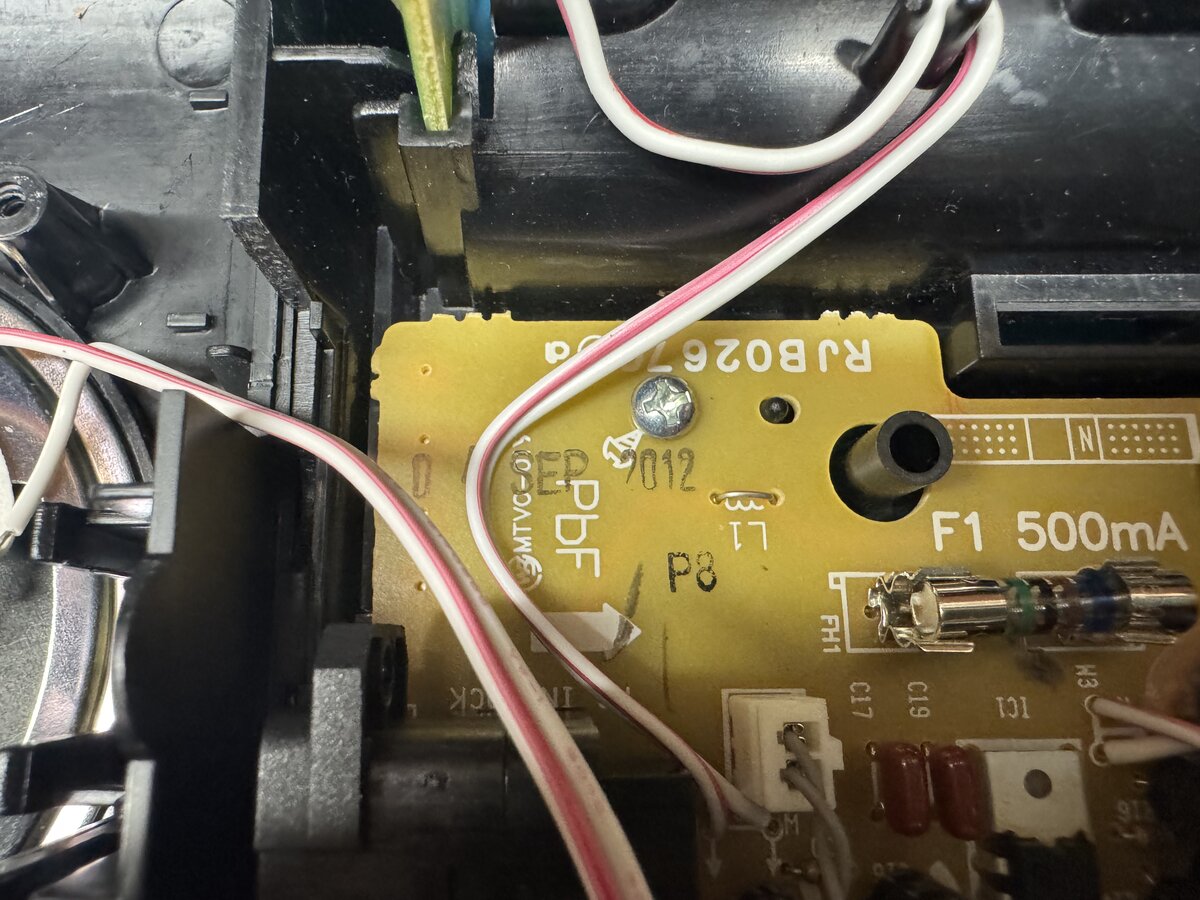
It was manufactured in 2012.
I plugged both the input and the output of the ACI into the tape recorder, as intended. The ACI has a 3.5mm female audio jack for input, and a 3.5mm female audio jack for output, and the tape recorder has corresponding female jacks as well.
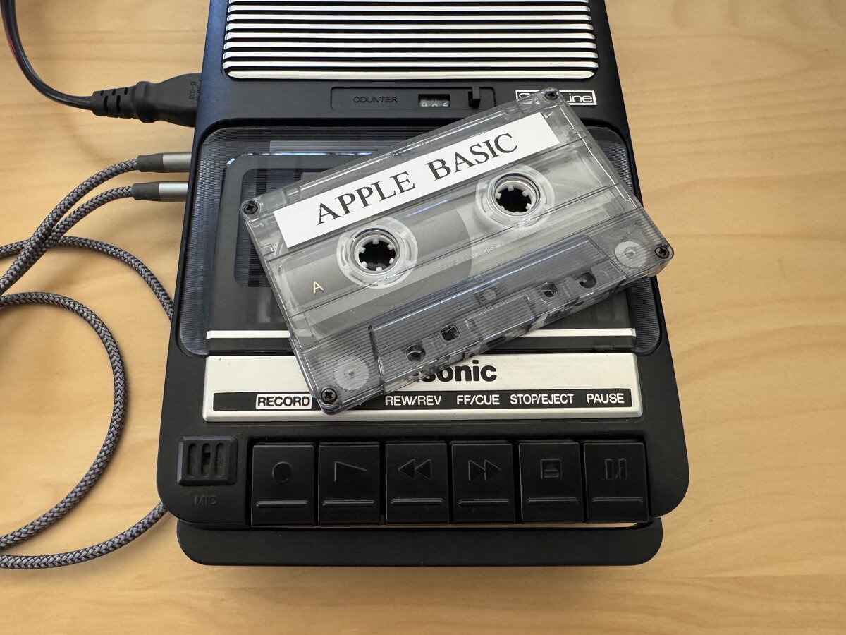
I wanted to load BASIC from tape, as a user would have done in the 1970s. There are a few ways to get a tape with BASIC on it.
- You can obtain a tape with the BASIC program already on it.
- You can make a tape yourself.
I chose the second option. But how? I could simply play the audio from my laptop and record it to the tape recorder. Instead, I did it the harder way: I reloaded BASIC from the computer into the Apple-1 as done above, and then saved it to tape from the Apple-1. I used the following command:
1
2
C100R
E000.EFFFW
As simple as that! The trailing W means “write,” and the E000.EFFF means “read from memory from E000 to EFFF.” I now had a tape with BASIC on it!
The next step was to write a simple BASIC program, save it to tape, and then reload it. I used a separate tape, to avoid mistakenly overwriting my BASIC tape. In the BASIC manual, Apple documented how to do this:
- write your program in BASIC
- press RESET to exit BASIC
- run the ACI program with
C100R - type
4A.00FFW800.FFFW - set the tape recorder to “record”
- press “RETURN” to start writing to the tape
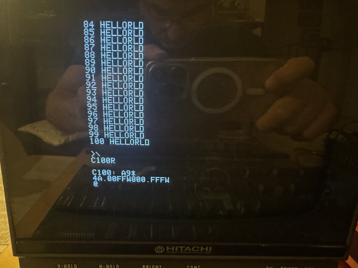
To read the program back, you run the ACI program again, type 4A.00FFR800.FFFR, set the tape recorder to “play,” and press return on the computer. Then you reenter BASIC not with E000R as usual, but with E2B3R. This enters BASIC without clearing the program memory. From there, it is as if you had just typed in the program read from tape.
It would be fun to do the same for my C program. You would need to do something similar to what is done with BASIC:
- identity the memory regions needed by the program
- add an entry point which doesn’t re-initializes the program’s working memory, in particular the heap
It’s probably an obvious thing to say, but the ACI does not remote-control the tape recorder, so you need to press the “play” or “record” buttons at appropriate times, as well as rewind the tape yourself. This is unlike big iron tape drives for the mainframes and minicomputers of the time, which were controlled by the computer.
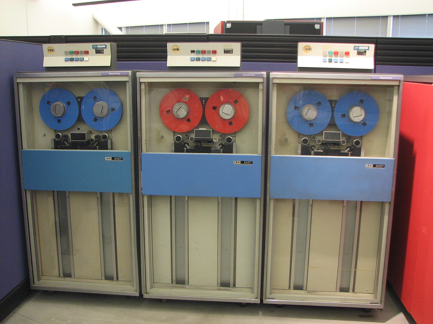
Photo credit: Erik Pitti, San Diego, CA, USA
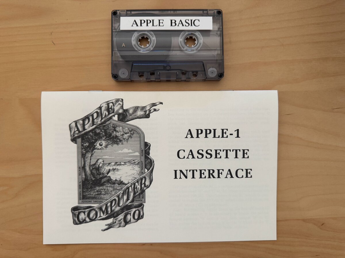
Manual
Apple made a separate small manual for the ACI. It is available in PDF online, but I had obtained a nice reproduction of the Apple Cassette Interface (ACI) manual alongside the regular Apple-1 manual and the BASIC manual.
Other work
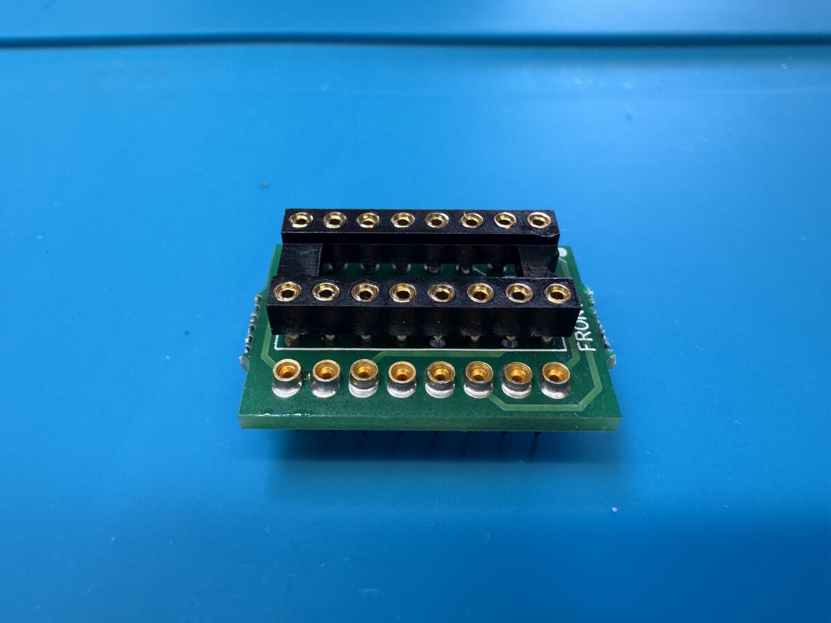
Mini keyboard adapter
Uncle Bernie designed a tiny Apple II to Apple-1 keyboard adapter. I assembled one without difficulty. You have to solder independent pins, as well as an SMD transistor, but I now have decent experience soldering small components.
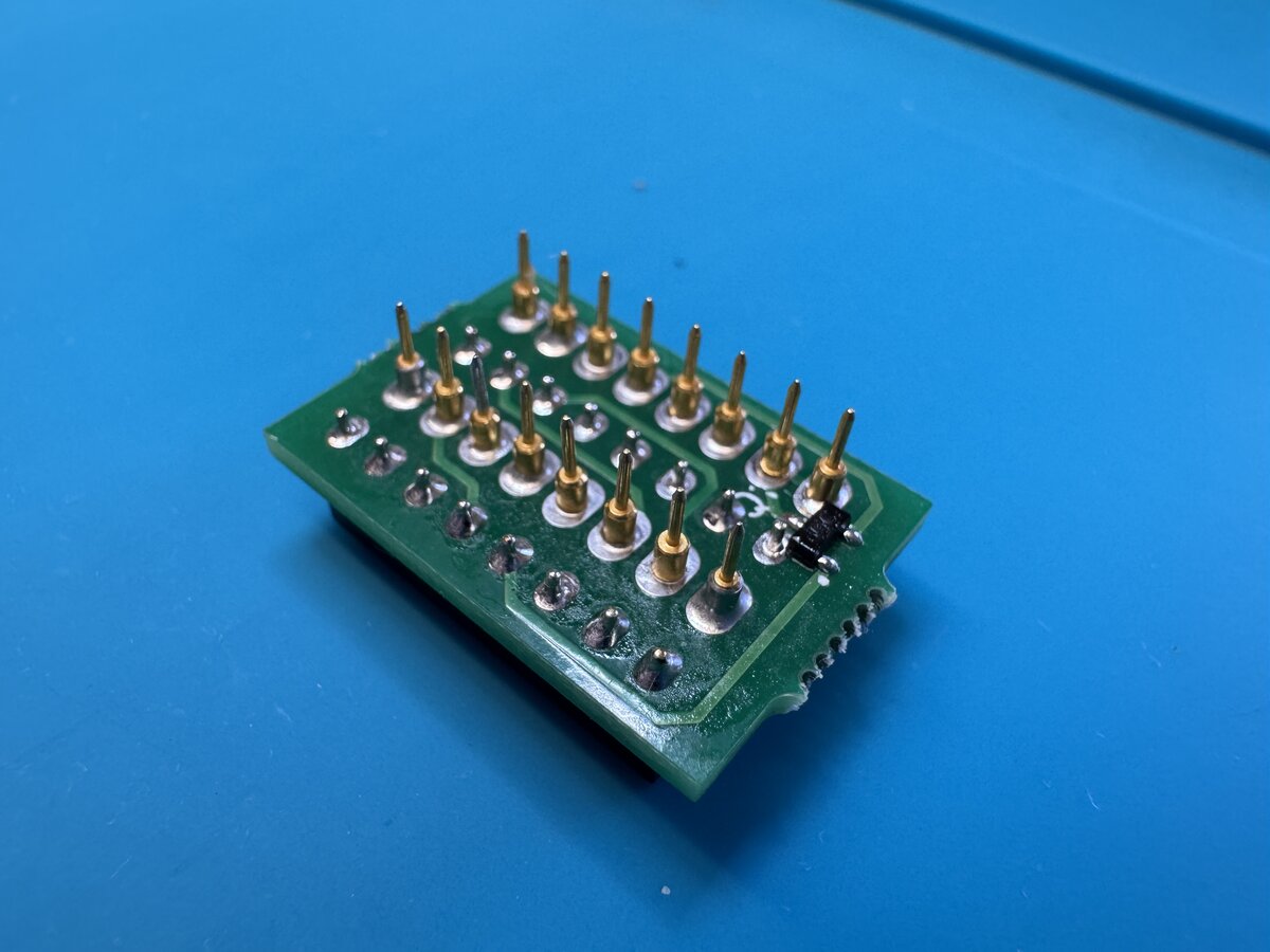
From the top:
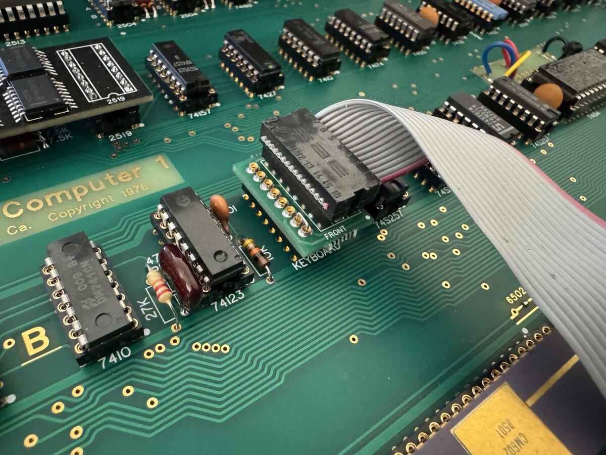
And in use:
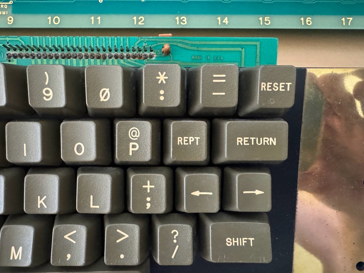
I also implemented Uncle Bernie’s Apple II keyboard mod, to make the rarely used REPT key act as a Clear Screen key.
For this, you have to:
- cut a couple of traces on the keyboard
- add a resistor
- add a couple of wires
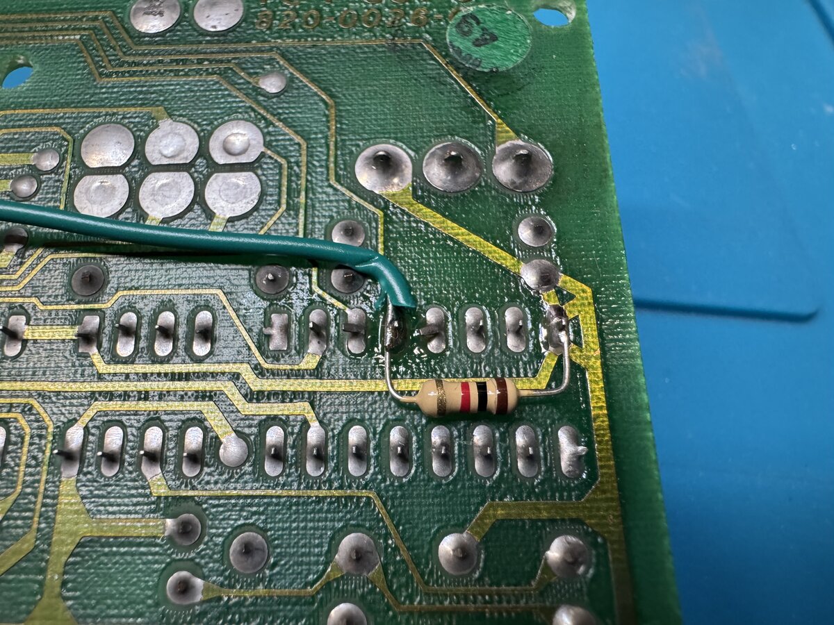
This still allows the keyboard to work with an Apple II.
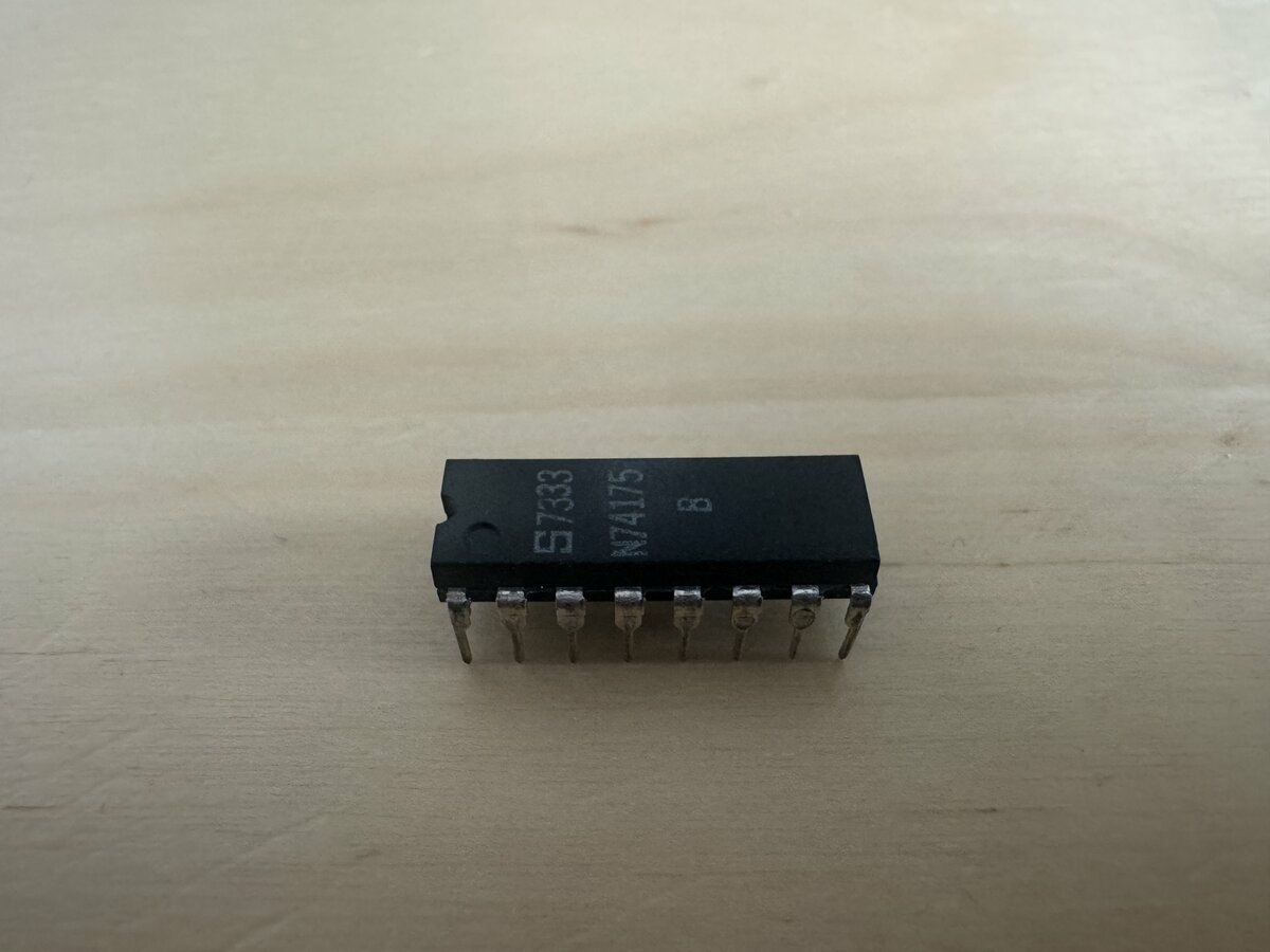
Failed 74175
Incidentally, as I got back to the Apple-1 after few months without turning it on, I found that it didn’t work anymore. The display was not showing what it was supposed to show, as if it didn’t synchronize. I tried a couple of monitors, cables, and eventually zeroed in on the 74175, a quad D-type flip-flop, made in 1973: swapping it for another chip, the issue was resolved. I tested the 74175 in my chip tester, and it showed as failed there too, unsurprisingly. Curiously, the chip must somehow have gone bad between the last time I had the Apple-1 on, a few months ago, and now.
Conclusion
I now have a fully functional Apple-1 reproduction, with a working ACI and tape recorder. The only thing missing from this setup would be a case. I am not yet sure if I will build one, although I have collected lots of pictures from existing cases, vintage and modern. If I do, I will plan to write a follow-up post.
Comments powered by Disqus.