
Introduction
This is part 2 of a two-part post. See also The IBM Magnetic Tape Selectric Composer - Part 1.
In the first part, I placed the IBM MT/SC in its context, described its various parts at a high level, and covered the input station in more details. In this part, I continue the exploration of the MT/SC, starting with the output station.
The output station (MT/SC)
Initial glance
The output station, or composing station, is what I call above the MT/SC proper. It consists of:
- a modified Selectric Composer
- a tape console
- a desk which contains electronics inside, and a control panel on top
There is a single power cable for the whole system, which goes to the desk.
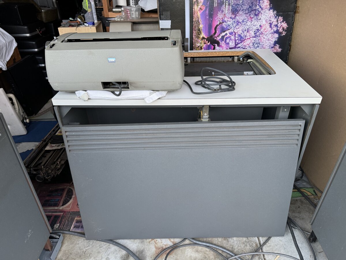
The Composer
As discussed at the beginning of this article, this is what I saw first of the system. The IBM Composer is a very recognizable, and beautiful, piece of equipment.
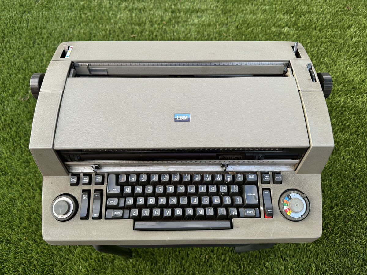
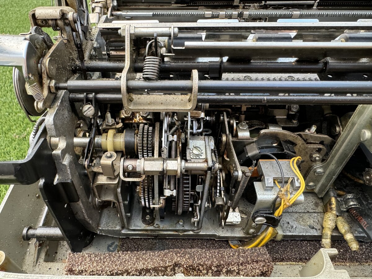
It looks significantly different from the regular Selectric, and this is reflected inside, which also differs significantly from the Selectric.
The Composer has a built-in cover, which you lift during operation.
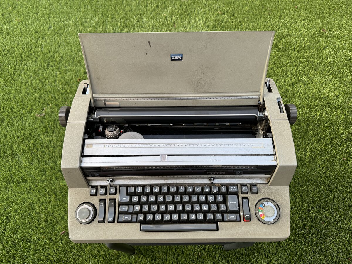
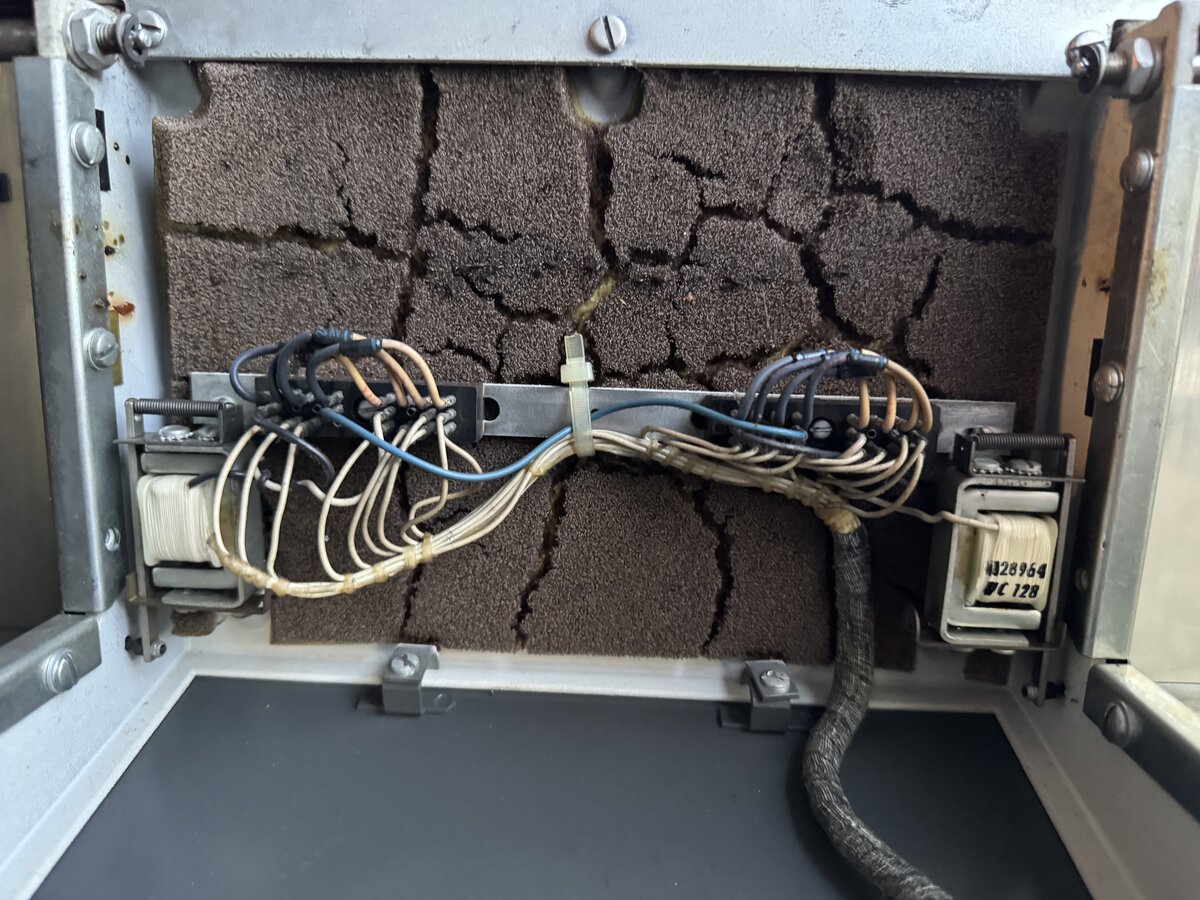
The top case is removed easily, like with the regular Selectric. The inside was full of crumbled sound deadening foam, a common occurrence in IBM typewriters.
You can see, on the back left, the part that deals with the proportional escapement.
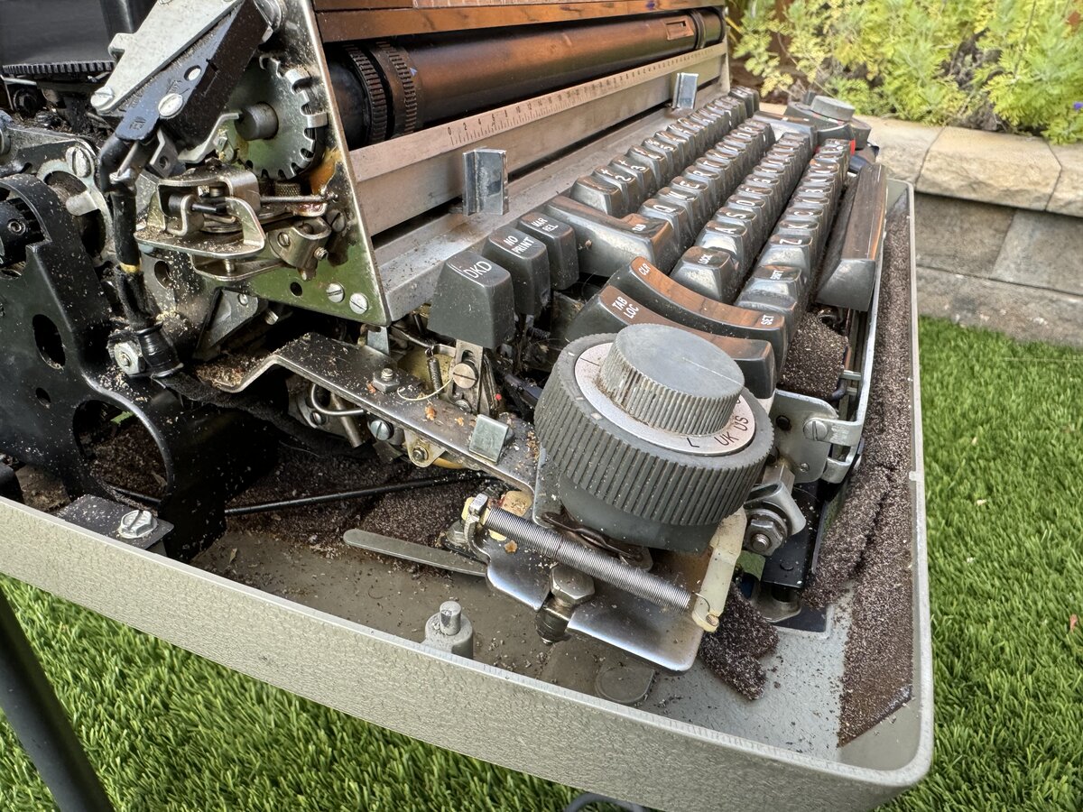
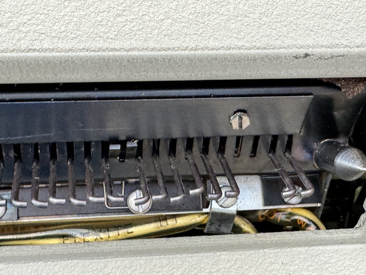
Now, the Composer part of the system is identical to the regular IBM Composer, is it? Well, almost, but not exactly! Indeed, IBM could have decided to build an I/O Composer, as they did an I/O Selectric. But they opted not to. The market was probably too small for this to make sense. So instead, IBM opted to electromechanically control a standard Composer from the outside. This required making a few small changes to the standard Composer:
- Add an opening at the bottom, with hooks, so that Composer keys can be activated.
- Add “photoelectric devices” inside the machine to detect the state of the machine’s cycle.
- Add a connector providing this information to the outside world.
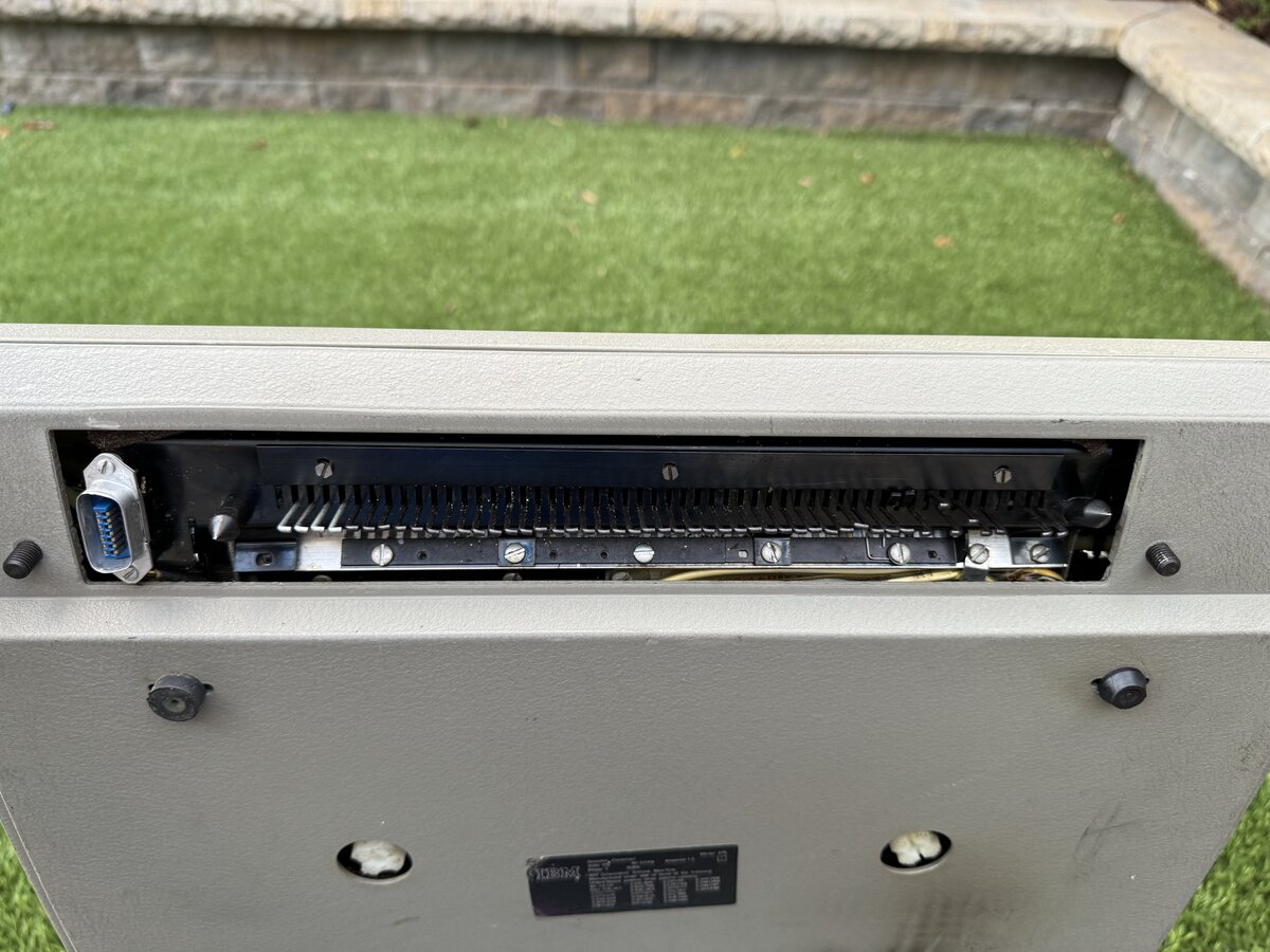
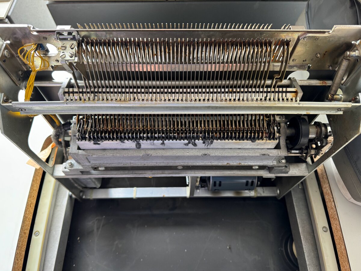
You can see how the hooks look like.
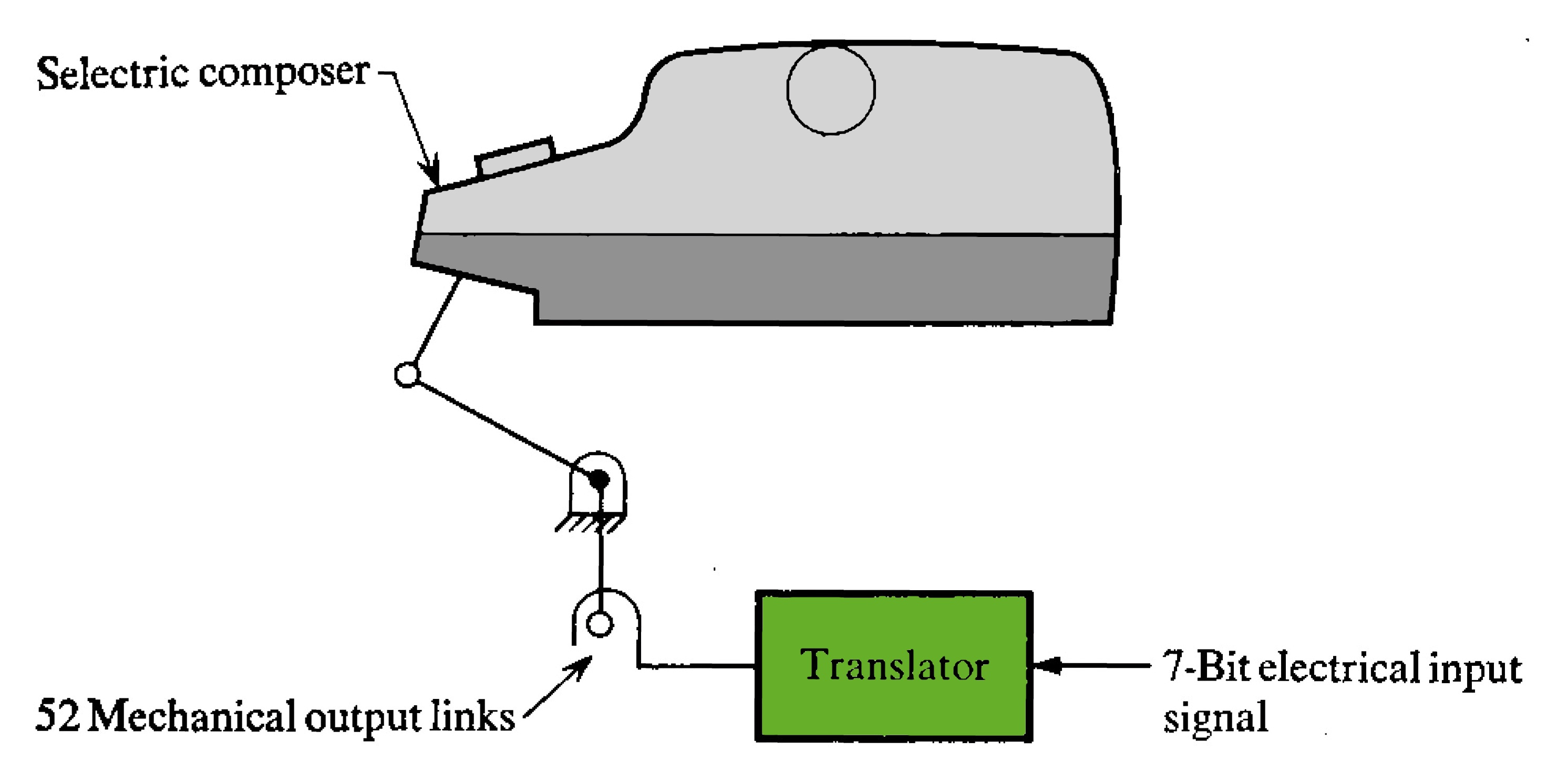
The electronics in the MT/SC desk control the Composer using an electromechanical interface device called the translator. Here is a diagram from IBM.
Here is a view from the top of the actual unit. The Composer simply sits on it. There is even an electrical outlet for the Composer power.
The translator base can easily be rotated up for servicing,
It includes its own electric motor.
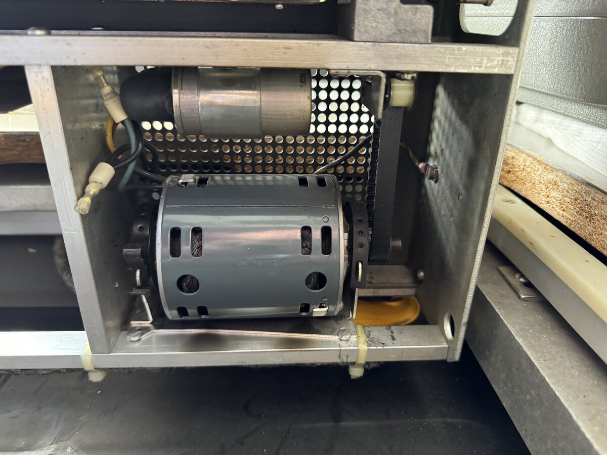
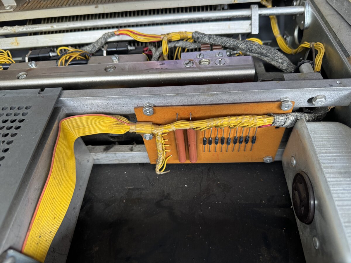
The translator also includes a small PCB, some switches, and some solenoids. Here, the PCB and the outlet next to it.
This introduces a synchronization problem, described by IBM in a 1968 paper. In short, the electric signals coming out of the modified Composer allow for synchronization, and for maximizing the throughput of the system.
Like for the MT/SR, the Composer has a rubber ring around it so it can nicely fit into the opening in the desk.
The Composer came with a dust cover.
The tape console
The MT/SC tape console is labeled:
1
2
Selectric Composer
MT/Reader
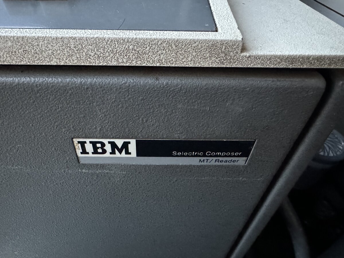
This indicates, or rather confirms, that the purpose of the tape station is to “read” magnetic tapes only.
The tape console include two so called “Tape Stations”: a left tape station, and a right tape station. My understanding at this point is that they are not identical: the left one is meant to hold a “correction tape”. while the right one holds a regular tape. The correction tape is typically produced from an MT/ST, but I am not sure an MT/ST Model V (MT/SR) can produce such a tape. Possibly.
UPDATE: Reading some documentation, it appears that you can create a correction tape with any MT/ST, including with Model V (AKA MT/SR). All it takes is the ability to write prefix codes to tape, which the MT/SR can most definitely do.
The tape stations are locked with two electromagnets. The MT/SR tape station has a single electromagnet.
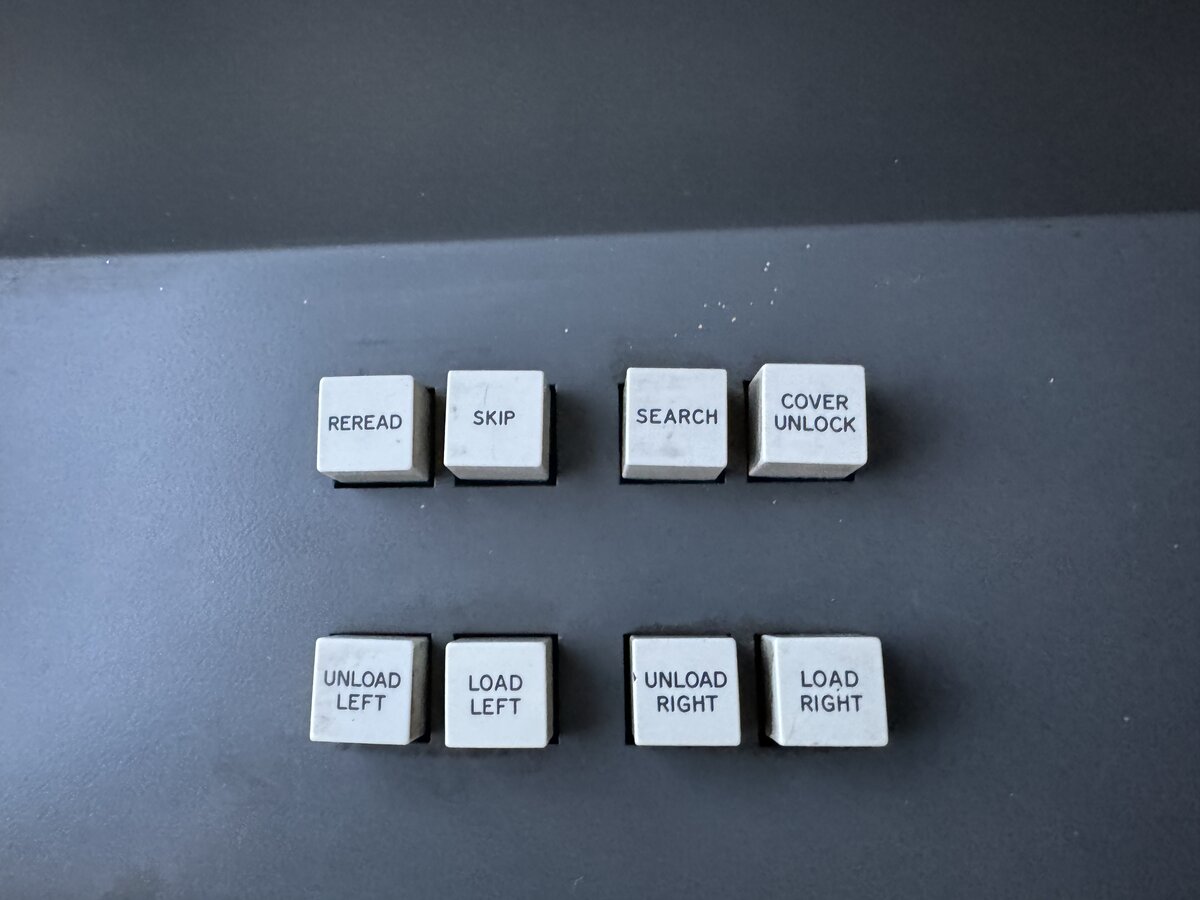
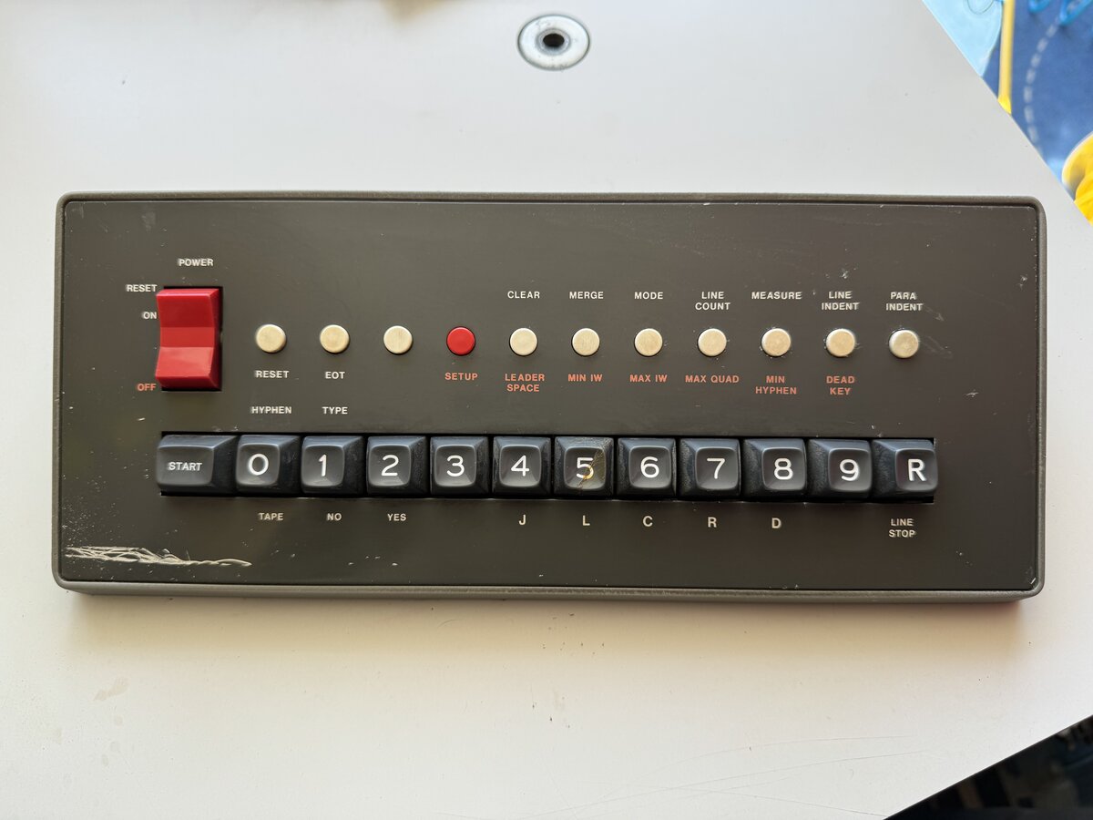
The control panel contains more buttons than the in put station’s tape console. It includes:
- REREAD
- SKIP
- SEARCH
- COVER UNLOCK
- LOAD LEFT and UNLOAD LEFT
- LOAD RIGHT and UNLOAD RIGHT
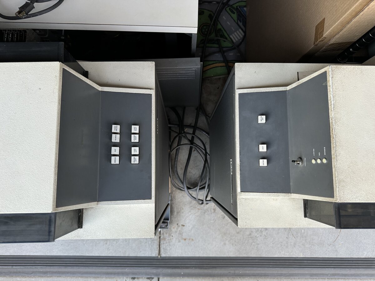
Compare the two tape consoles’ control panels:
The inside of the tape console is similar to the other tape console, except:
- there are two tape stations on top (but they share most of the components)
- there are two tape trays inside
- there is no electronics cage at all
- there is no power supply
The tape console has a cable that connects to the MT/SC desk. There is no removable connector, so the cable is permanently attached to the console.
There are 2 tapes inside the machine, loaded in their respective stations. They are not labeled. The fact that there are two hints that the “correction tape” might have been in use, and that, therefore, it was possible to make use of such a correction tape, and even maybe produce one from the MT/SR.
UPDATE: This is possible, see further comments above.
The desk and electronics
This part is the heart of the whole MT/SC system. So it is important to spend some time on it.
As already mentioned, this is not just a “desk”, of course. It is a desk that contains significant electronics, in addition to the translator discussed above.
The top of the desk features a control panel. This is built into the desk at that specific angle, so that it can face the user sitting at the Composer.
The cover of the panel can be removed, to reveal more functions:
A lot should be said about this control panel at some point.
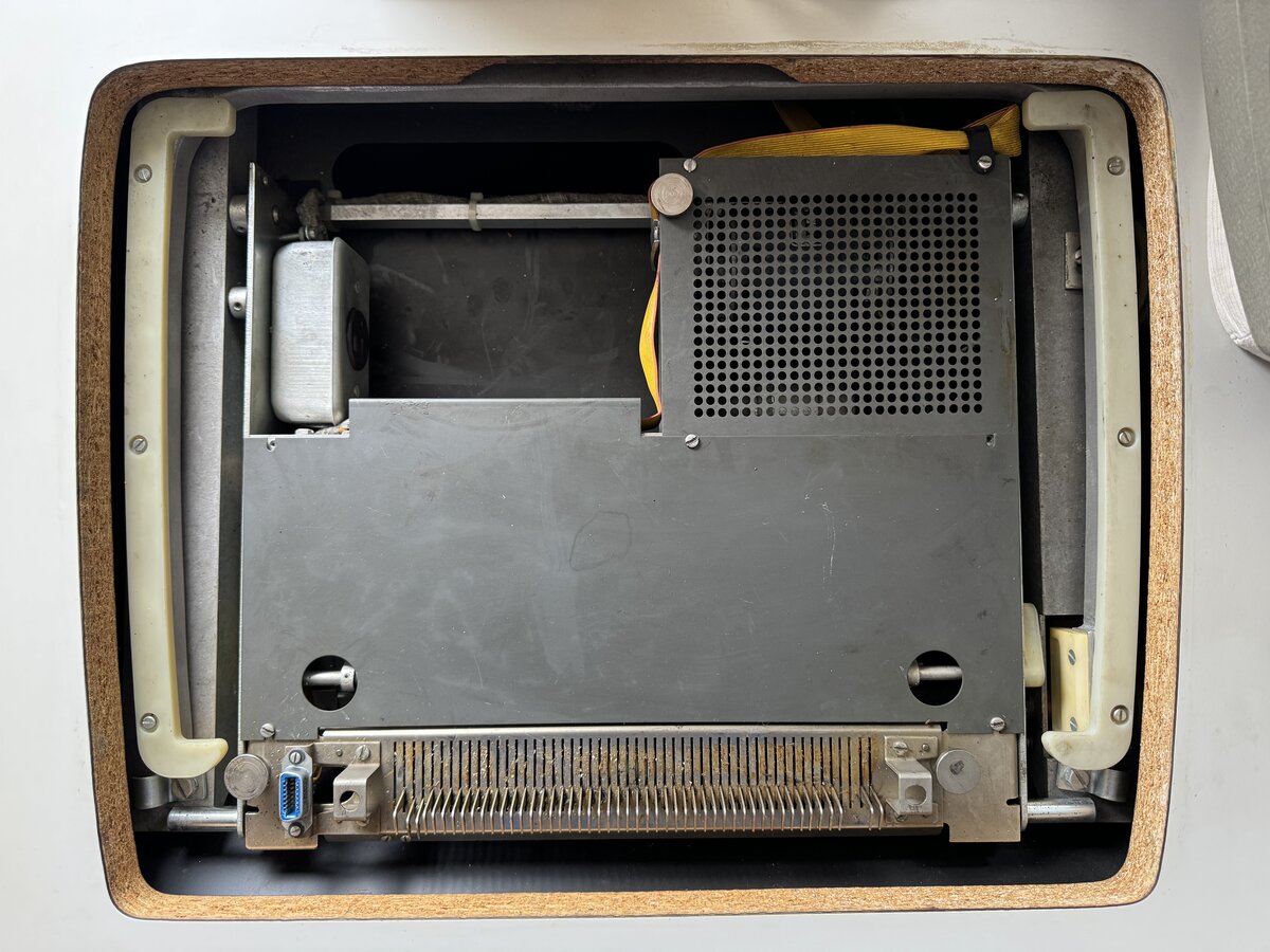
The electronics of the desk are accessible from the back. There is a large cover, which should usually be closed.
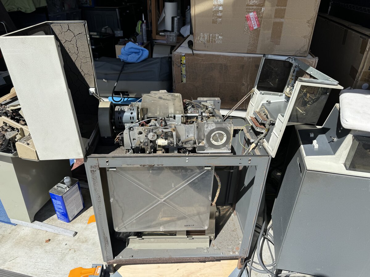
Taking it fully off reveals the electronics inside.
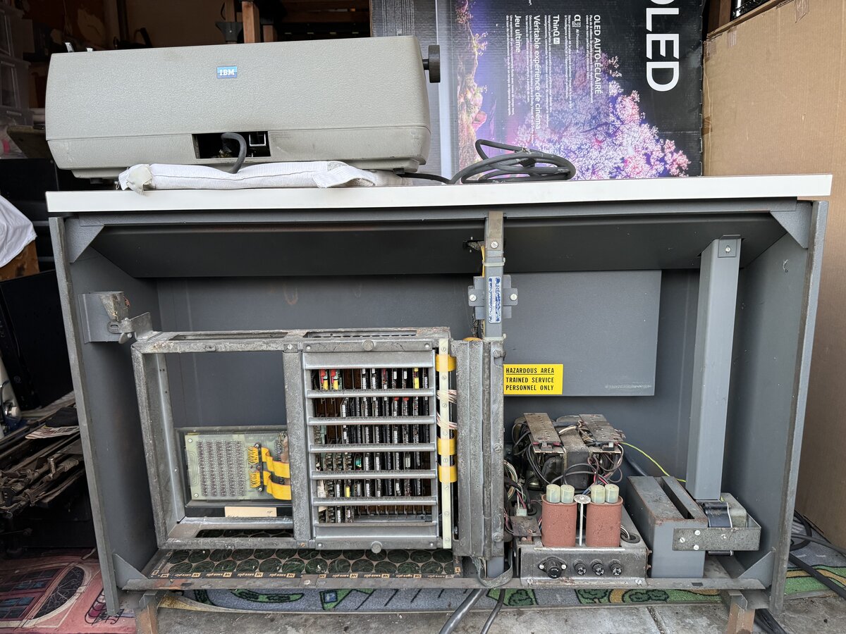
On the right, we have a large fan and the power supply.
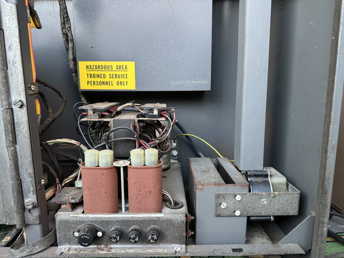
There is obvious corrosion on some of the metal capacitors’ cases.
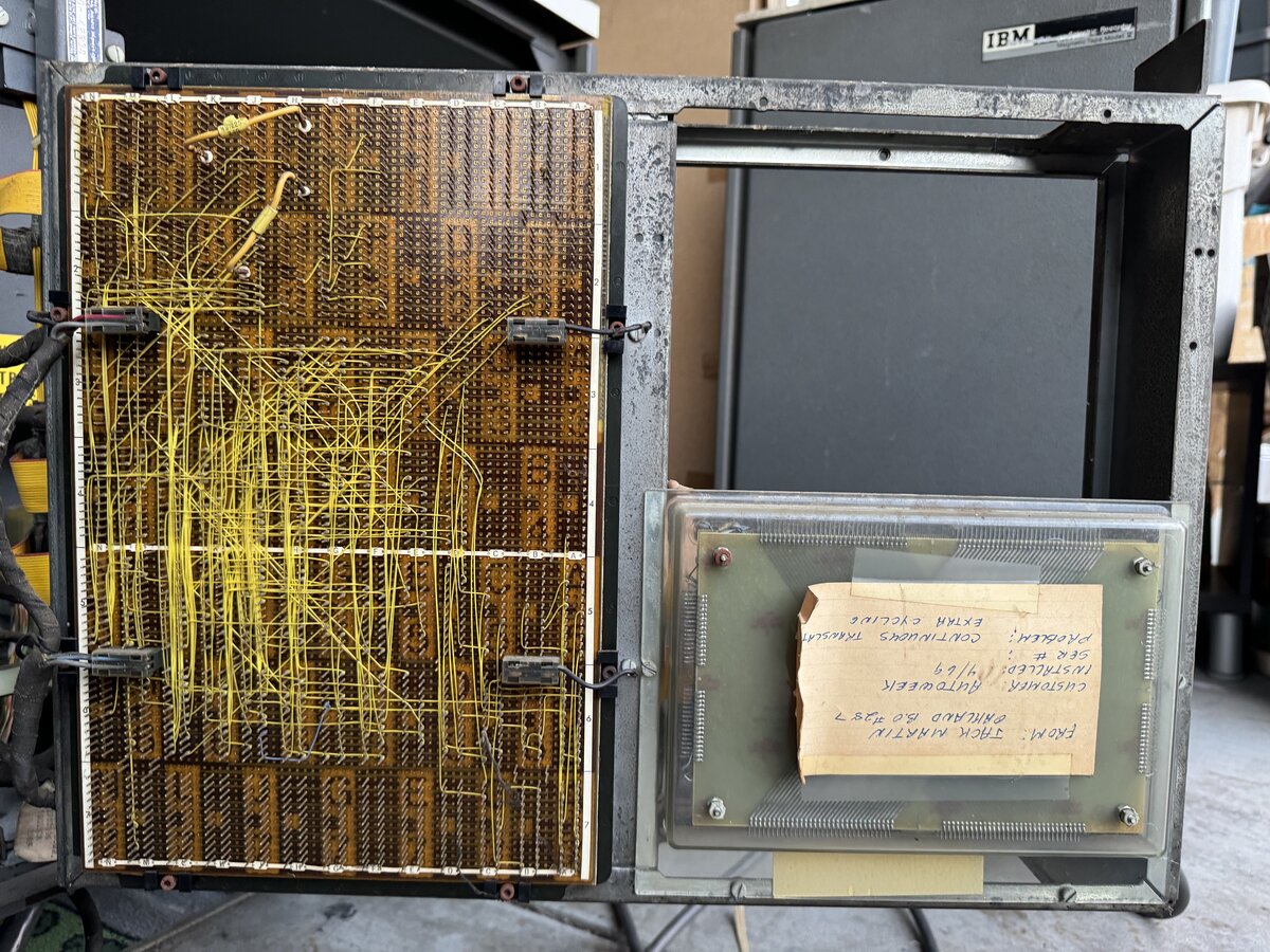
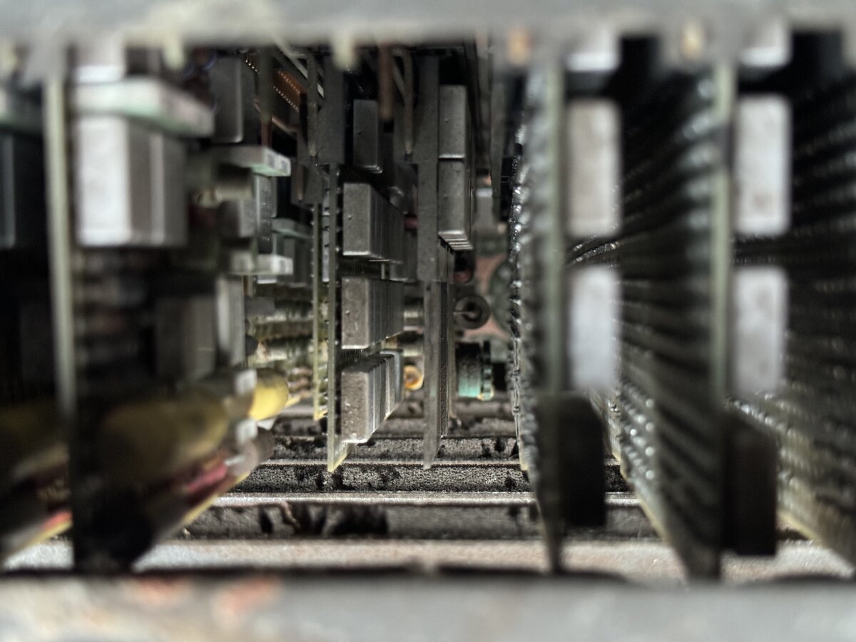
On the left, there is a card cage, and a separate electronics board.
The card cage can swivel, and you can easily see the back, which features a partially wire-wrapped backplane.
Some funtional areas of the card cage can be established already, even without looking at the diagrams.
.jpg)
The separate board, in fact, contains the 2 KB core memory, while the card cage contains the rest of the electronics, including the memory controller. The cards are made essentially of IBM SLT modules.
Interestingly, the back of the core memory features a note which says:
1
2
3
4
5
6
7
8
FROM: JACK MARTIN
      OAKLAND B.O #287

CUSTOMER : AUTOWEEK
INSTALLED: 4/69
SER #    :
PROBLEM  : CONTINUOUS TRANSLATOR
           EXTRA CYCLING
This tells us that a certain Jack Martin, working out of Oakland, installed or replaced the core memory in April 1969.
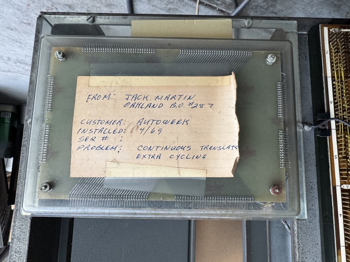
Now what’s really funny is that I posted about this in the Golfball Typewriter group on Facebook, and someone replied that they had worked in Oakland in building 287, that they had known Jack Martin, and that he was indeed in charge of MT/SC machines. We are talking about a note installed in this machine almost exactly 50 years ago! What a small world!
I notice one single missing part: the document holder that plugs on the desk. The MT/SR desk did come with its document holder.
The MT/SC electronics
Besides full reverse-engineering, there is some good news about the electronics. Indeed, we have two major sources of information:
- the maintenance diagram manuals
- the article “Development of the Magnetic Tape Selectric Composer”, published in 1968 in the IBM Journal of Research and Development
I knew the second resources existed, but it took me a while to find a way to download it online. But I did. That 19-page article contains a number of invaluable insights into the MT/SC.
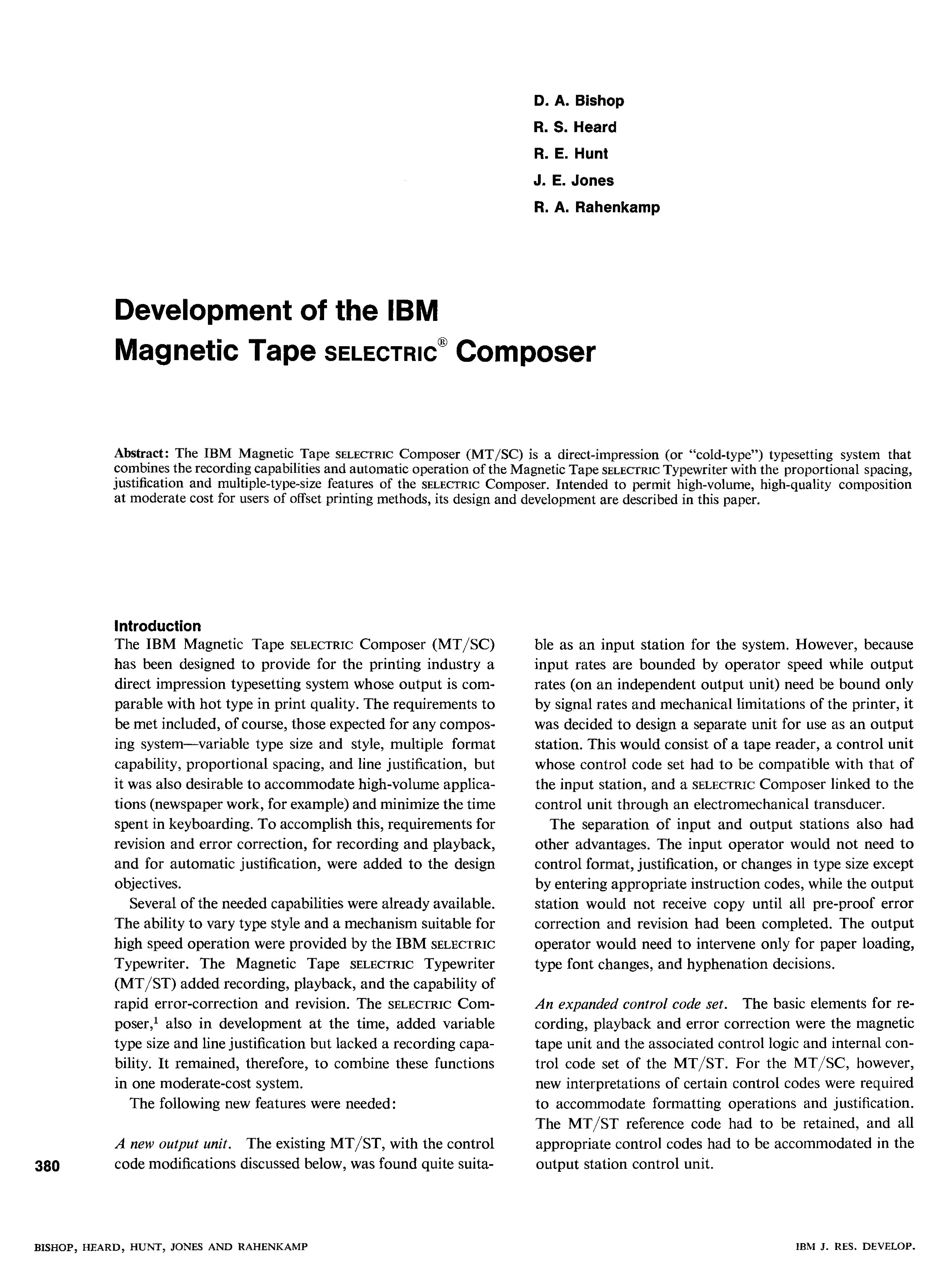
From it, in particular, we know that the electronics in fact implement a very simple processor, and we even have the format of the simple 16-bit instructions!
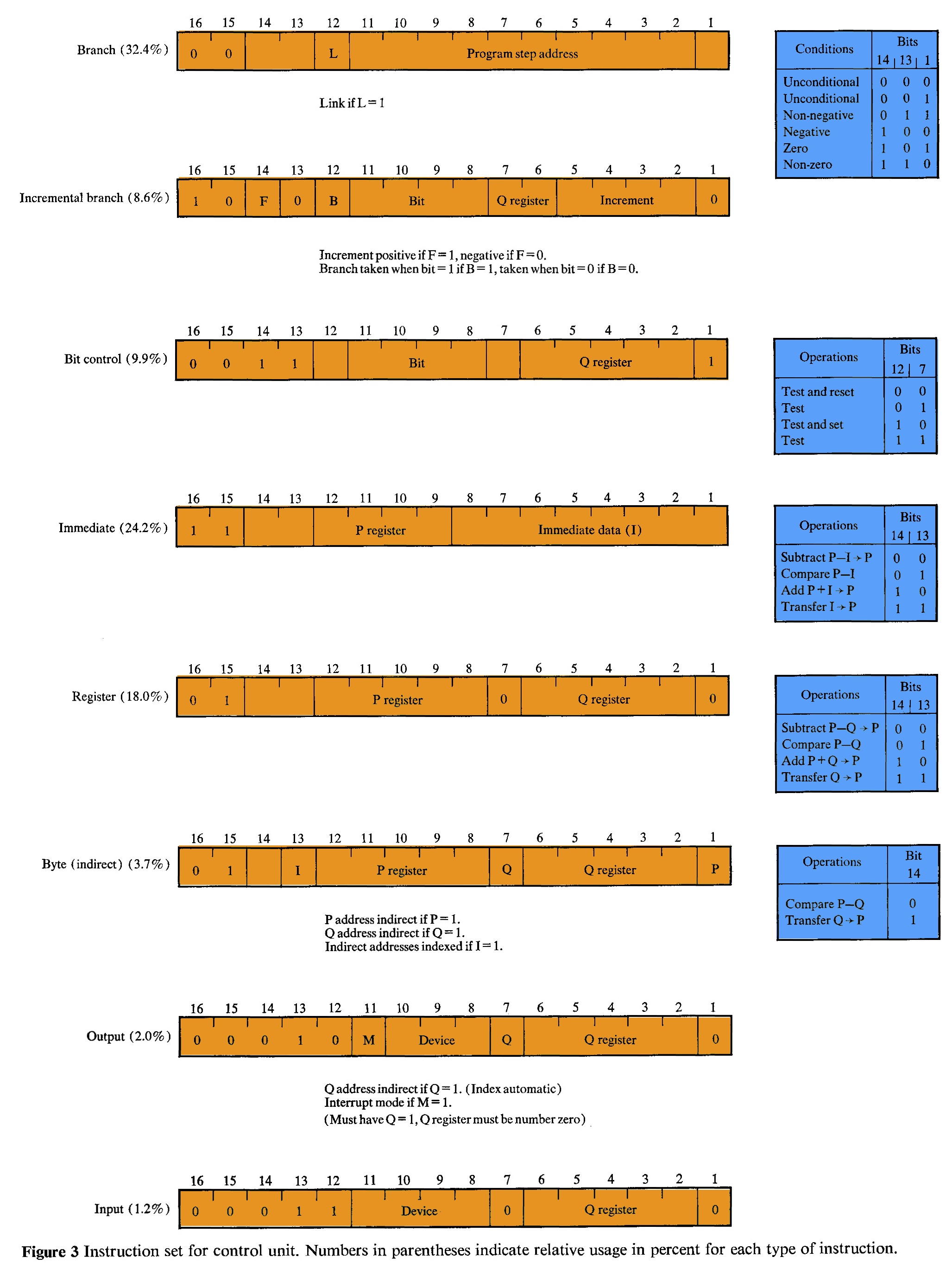
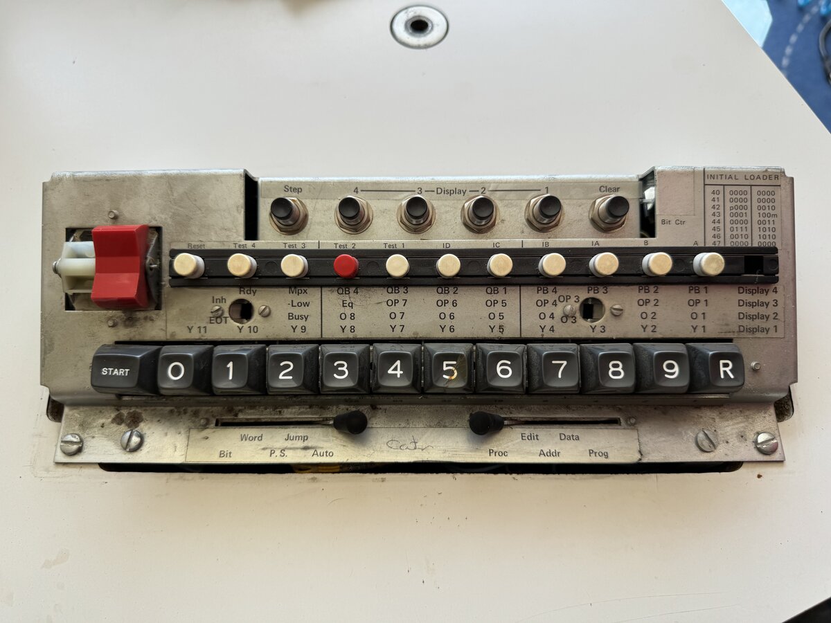
In fact, before I was able to obtain a copy of that article, I mused about the fact that the system might contain an interpreter. This was hinted at by the fact that there was clearly memory, and some notion of “program” was mentioned in the diagrams, and some labels on the MT/SC’s control panel hinted at loading a program (“Initial loader”) and stepping through instructions.
I wondered whether the program for the system might have resided on a special tape, which the operator would have to load in memory every time the machine was to be used. I also wondered, if not on tape, where the width of each character would be encoded so that justification could take place. I hadn’t thought that the program and justification tables could simply reside in the non-volatile core memory, as explained below. But I wasn’t that far off.
The tasks of the machine, while simple in modern terms, were considered too large to implement in discrete logic, as was the case with the MT/ST and its relays bank. So the engineers went for a very flexible solution: a custom processor, with a small instruction set, and a microprogram stored in core memory. This allows the machine to process text coming from the tape, justify it, and send it to the Composer for output.
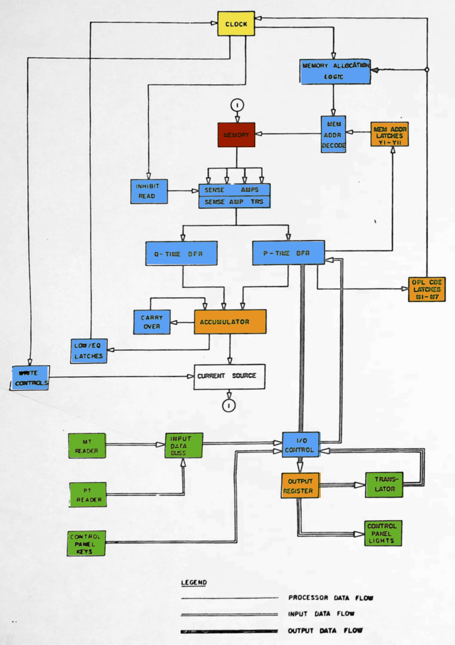
The microprogram was stored in core memory at the factory. Because core memory is non-volatile, this was possible, and it acts as an EPROM or as Flash memory. In addition, the core memory also acts as RAM for buffers, and even as processor registers. The following diagram illustrates the general architecture of the processor.
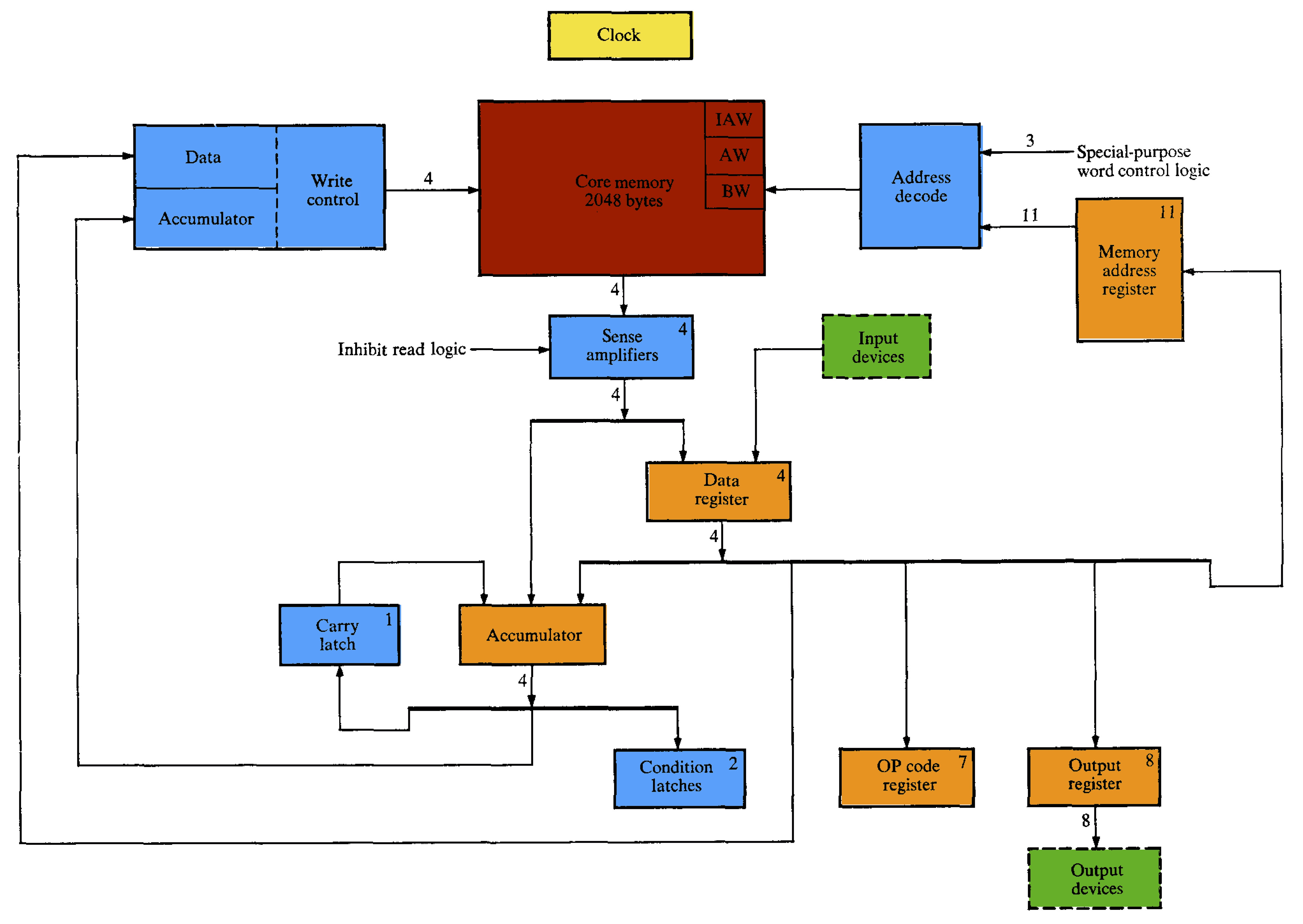
A similar diagram is present in the maintenance binder. Both appears broadly compatible.
We are so much better prepared here compared with newer IBM machines which are absolutely undocumented!
This said, there is a huge challenge: after 45 years, can we still recover the microprogram from the core memory? It is not impossible that the program has remained. However, core memory read cycles are destructive, and if the memory controller is not working properly, we might lose the program. So we need to be very careful.
If worse comes to worst, we could write a new microprogram. But wouldn’t it be cool to recover the original one, and see how the IBM engineers dealt with all the functions of the machine in such a small amount of memory?
Accessories
Tapes
The MT/SC system is designed to work with magnetic tapes. IBM designed a completely new tape system, as far as I know, for the MT/ST. The MT/SC uses the exact same system, of course, as it had to be fully compatible with existing MT/ST that act as input stations.
The tapes are designed to be very user-friendly. The target users were not computer users or even technical personnel, but secretaries and office workers. The tapes are enclosed in a transparent plastic cartridge, and as easy to handle as an audio cassette tape (a format released in 1963).
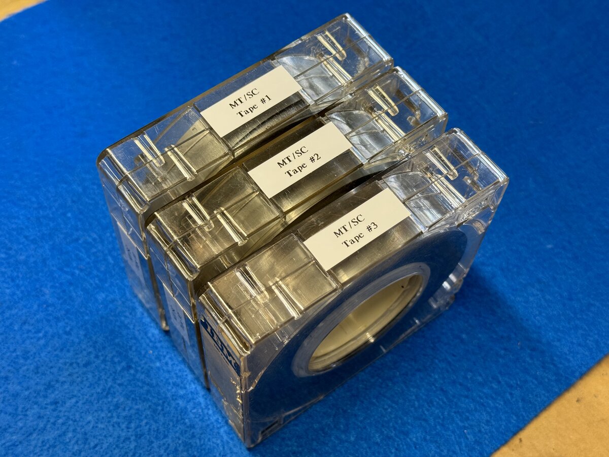
In addition to two tapes present in the MT reader of the Magnetic Tape Selectric Composer, there were 3 dirty tapes that came with this system.
I decide to clean them right away as I couldn’t stand the dirt. One of the tape cartridges opened very easily, so I decided to just clean the cartridge with water and detergent.
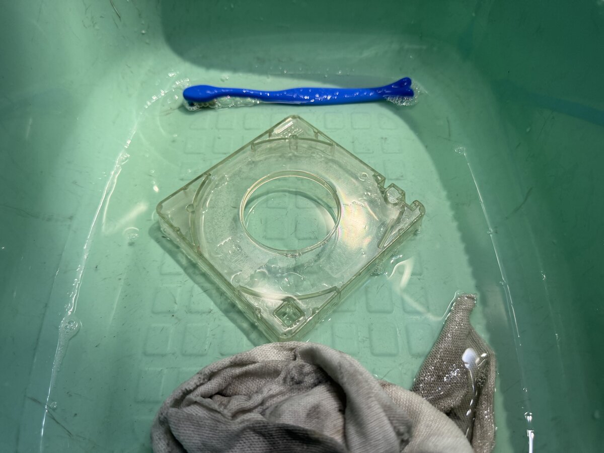
I also managed to open the other tapes, although I did break a plastic tab or two. Dirt had come into the tape cartridges, so I gently blew air and brushed away the dust, while I properly cleaned the cartridges. I also cleaned the hubs with Q-tips.
Here are the 3 tapes after I cleaned and labeled them.
Here is how you handle the tapes (in theory - I haven’t been able to try this yet):
- Press the “UNLOAD” button on the tape console. An existing tape in the machine will be rewound, and the tape cover will open (or unlock) so we can remove it.
- Place the new tape in the tape console.
- Close the cover.
- Press the “LOAD” button. The cover will lock, and the tape will be loaded into the machine.
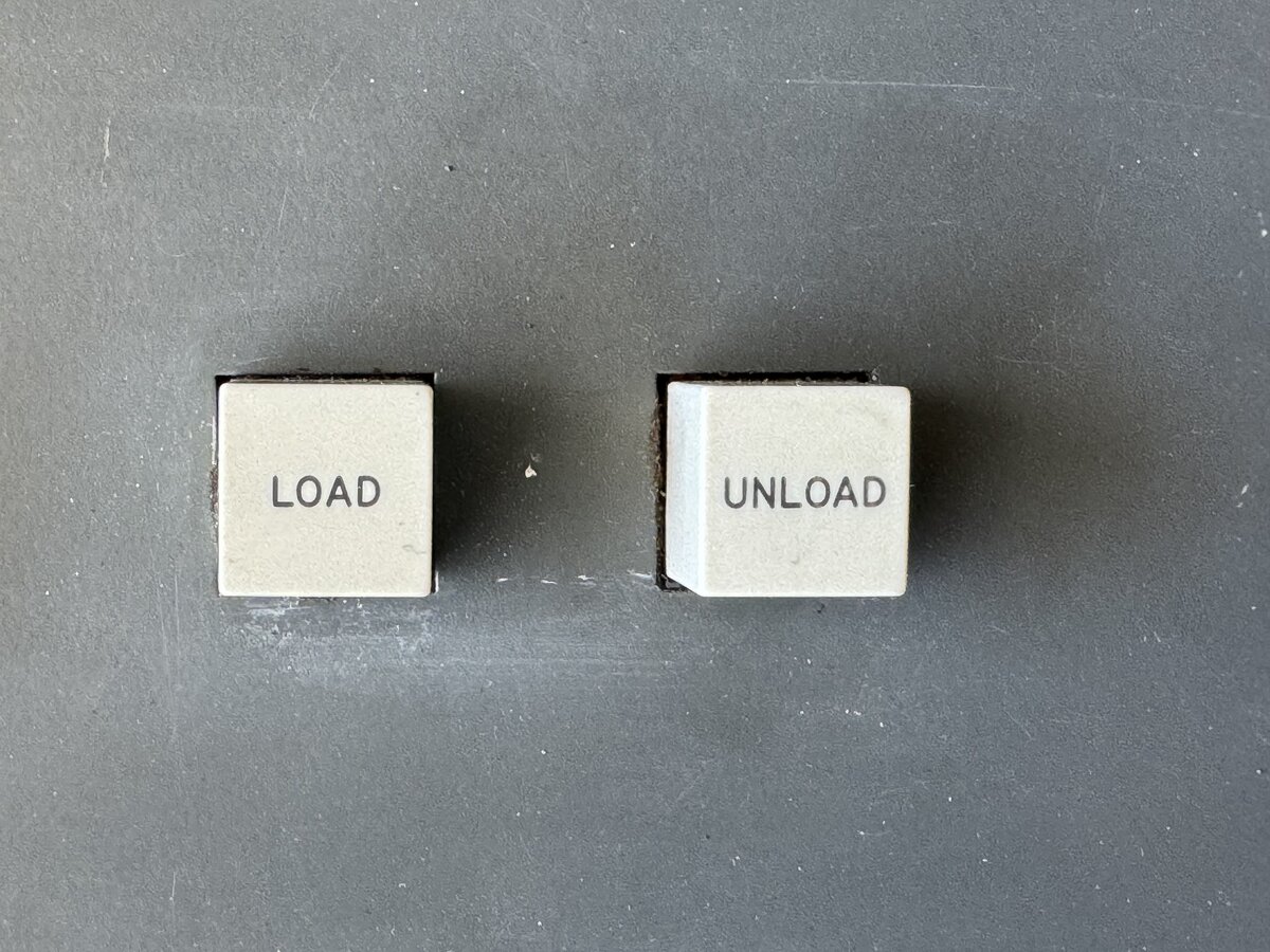
Like with a compact cassette, there is no manual winding or spooling of the tape needed. Even better, here the surface of the tape is never exposed to the user, and it’s always guaranteed to be fully wound in its cartridge.
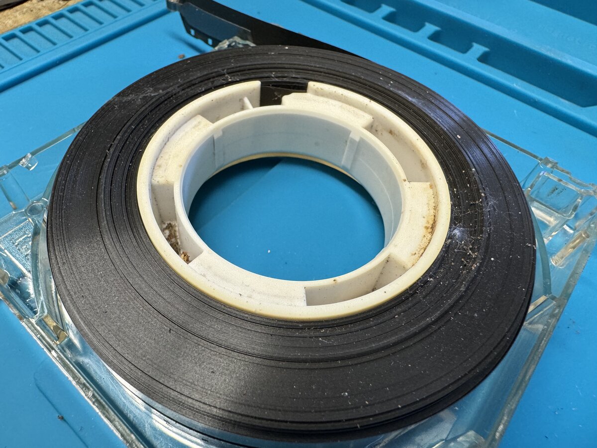
Each tape has a little eyelet on its end. You can see this on the following picture, as well as the sprocket holes in the tape.
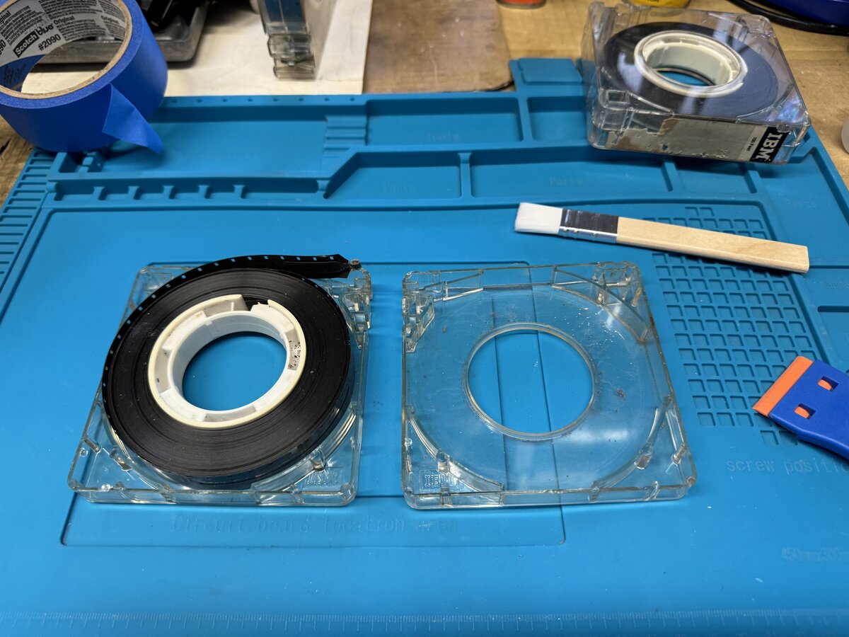
Inside the machine, the tape drive has a pin that grabs that eyelet and pulls the tape into the machine. There is no take-up spool inside the machine: instead, the tape gently folds into the plastic bin inside the machine. Also, the tapes have a track with sprocket holes, which allows the machine to drive them.
There is a fixed, plastic tape end inside the machine, that on one hand dips into the tape tray, and on the other hand hooks into the end of the actual tape. You can see it in this picture:
The tapes are quite low density: each character includes 9 bits and is written across the 16 mm width of the tape, at 20 characters per inch. Each tape contains 100 feet of 16 mm magnetic tape. Approximately 24,000 characters can fit on a tape. IBM’s estimate was that this would be equivalent to about 10 standard pages of text.
Tapes, while playing back text, would go at about 15.5 character/second. The MT/ST search function is advertised as 900 character or 45 inch/second, while rewinding the tape would go at 32.5-52 inch/second.
Composer type elements
The Composer also came with a box containing 18 type elements - one of them being a regular Selectric type element, but the others being Composer type elements. Indeed, the Composer had its own, different type elements, incompatible with the Selectric’s.
| UN-10-L | UN-8-B | AR-8-I |
| UN-8-L | UN-8-MI | UN-10-B |
| UN-8-M | UN-11-B | UN-10-M |
| UN-11-MC | PR-8-M | ORATOR [regular Selectric] |
| PR-8-B | PR-10-B | UN-11-M |
| UN-7-M | B-12-B | UN-11-MI |
In addition, element PR-10-M was installed on the machine.
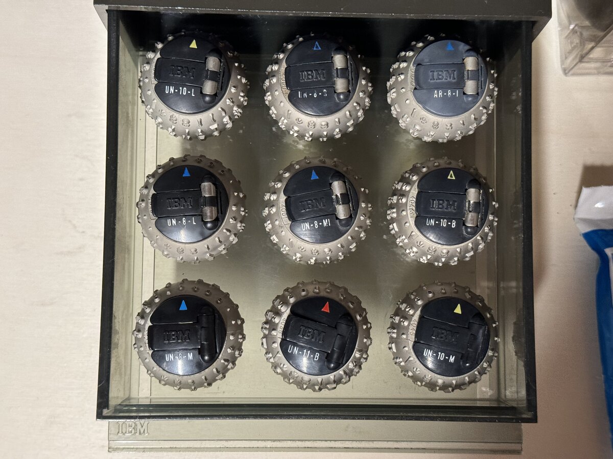
Composer elements are named consistently. For the fonts above:
UN: UniversalPR: Press RomanB: Bodoni Book
The middle number indicates the size of the font in points, while the last part indicates the variant:
M: MediumB: BoldI: ItalicMI: Medium ItalicL: Light
I have since acquired a few more type elements (thank you Ted and others!).
The maintenance diagram manuals
An important part of the system are the “maintenance diagram manuals”. There is one for the MT/SC, and one for the MT/SR. These large binders contain what should be invaluable information about the system.
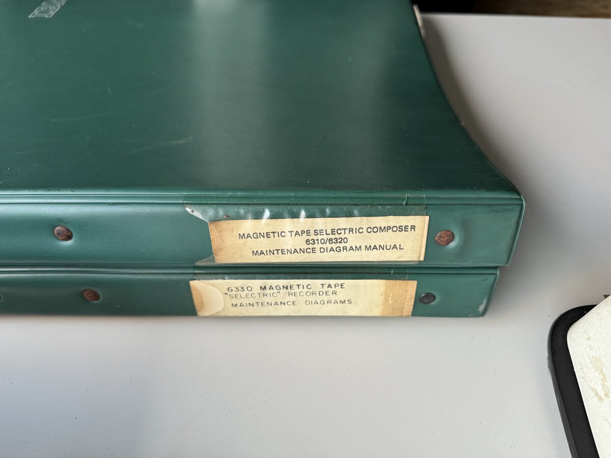
IBM service manuals, in general, are very well done and include, for each aspect of the machine, a “theory of operation” section. In short, you can peruse a service manual, and have a really good idea of how the machines works. This is not so here, with the “maintenance diagram manuals”: they don’t include are any explanations whatsoever!
However, they contain a lot of detailed diagrams, including (as copied from the MT/SC binder’s table of contents):
- data flow diagrams
- intermediate logic diagrams (ILD)
- function charts
- ALD net listings
- timing diagrams
- power supply diagrams
- wiring diagrams
- code charts
- MT reader diagrams [for the magnetic tape reader]
- PT reader diagrams [for the optional paper tape reader]
- memory diagrams
- ALD card circuits
- ALD (Automated Logic Diagrams)
The MT/SR binder contains similar diagrams, but they are much simpler.
Both binders appear fully complete. The MT/SC binder contains 122 pages with text and diagrams, while the MT/SR binder contains 38 pages only.
I was graciously lent/donated a CZUR scanner by Ken Shirriff. With it, it was a breeze to scan the content of both large binders. Thank you, Ken!
I should note that we are also missing a user manual for the system. We do have manuals for the MT/ST, for the Composer, but not, specifically, for the MT/SC. If you know of such manuals, which definitely must have existed at the time, please let me know! The “Development” article contains the closest we currently have from a user manual!
UPDATE: I now know of a partial manual: “IBM Magnetic Tape Selectric Composer - Guide to Copy Preparation”. There is also a manual online entitled “IBM Magnetic Tape Selectric Composer - Record Unit Training Guide MT/ST Models II and IV (for Graphics)”.
There is mention in the available documents of a paper tape reader. This was an optional interface and device to read existing paper tapes in a format called TeleTypeSetter (TTS) used by newspapers. This instance of the MT/SC doesn’t come with this interface. It is unclear how widespread this standard was.
Additional context
Provenance
We know from the service records that came with the machines that they were in use from 1969 to 1978 at least. The customer mentioned on Jack Martin’s note is “Autoweek”, a car magazine. However, the service notes mention “Coon Litho”, a company that I haven’t been able to trace.
The seller mentioned that her grandfather, unfortunately long passed, somehow acquired this system after it was decommissioned, and put it in his garage, where it stayed for the next 45 years. This is how this system was saved from destruction, and how we now have an opportunity to study it, document it, and, possibly, restore parts or all of it.
It would be interesting if we could, at some point, read text from the tape, and see if indeed there is some Autoweek magazine content.
Rarity
I mentioned at the top of this article that we, at of July 2024, do not know of any other surviving MT/SC. There are a few known MT/ST (none of them working, that we know of), but no MT/SC. Why would that be? Well, clearly there were less MT/SCs made compared to the MT/ST. The MT/SC was designed for a very specific market of cold typesetting, while the MT/ST was much more widely applicable.
In addition, and this applies to many IBM systems, these systems were expensive, and therefore often leased to customers. Once the leasing period was up, given the speed at which technology was moving in the 1960s, 1970s, and 1980s, the machines were usually thoroughly obsolete, and IBM would scrap them. A similar fate awaited machines that were bought (like our instance, probably) instead of leased anyway, as they were large, obsolete, and not pretty or collectible.
Well into the 21st century, I can only disagree that these machines are not collectible, but imagine the situation around 1980, which such machines would typically be decommissioned.
Therefore, we are extremely lucky that any such machine has survived. I do hope that there are more, and I still hope to put my hands on an MT/ST at some point, but let’s see!
Pricing
We know from IBM ads, in particular, that the 1964 MT/ST was priced at $10,000 of the time, or about $100,000 in 2024.
A 1967 document quotes the MT/SC proper at $16,550, which is about $150,000 in 2024 US dollars. The MT/SC therefore was about 50% more expensive than the already-expensive MT/ST. In addition, you would need to add an MT/ST to the system for the input station, unless you opted for the relatively cheaper MT/SR (AKA MT/ST Model V, see below).
The same 1967 document quotes the MT/SR at $3,950, which is about $35,000 in 2024 US dollars. This equates to less than half the price of the MT/ST Model IV.
Even the single-Tape Station MT/ST Model II was much more sophisticated than the MT/SR:
- it could read and write from and to the tape
- it had simple word-processing abilities
- it no doubt included the sophisticated relay bank
- the typewriter was a full-fledged I/O typewriter
It is pretty clear that the MT/ST Model V AKA MT/SR was designed specifically as a cheaper input system for the MT/SC. The system would have quite limited applications besides that.
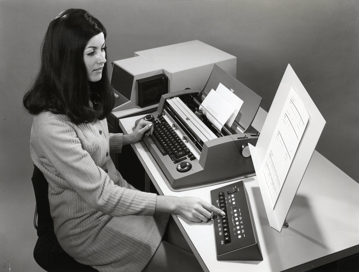
Relationship with the IBM 2741
As an aside, I was curious as to how the MT/ST relate to the IBM 2741 terminal, used for the famous System/360.
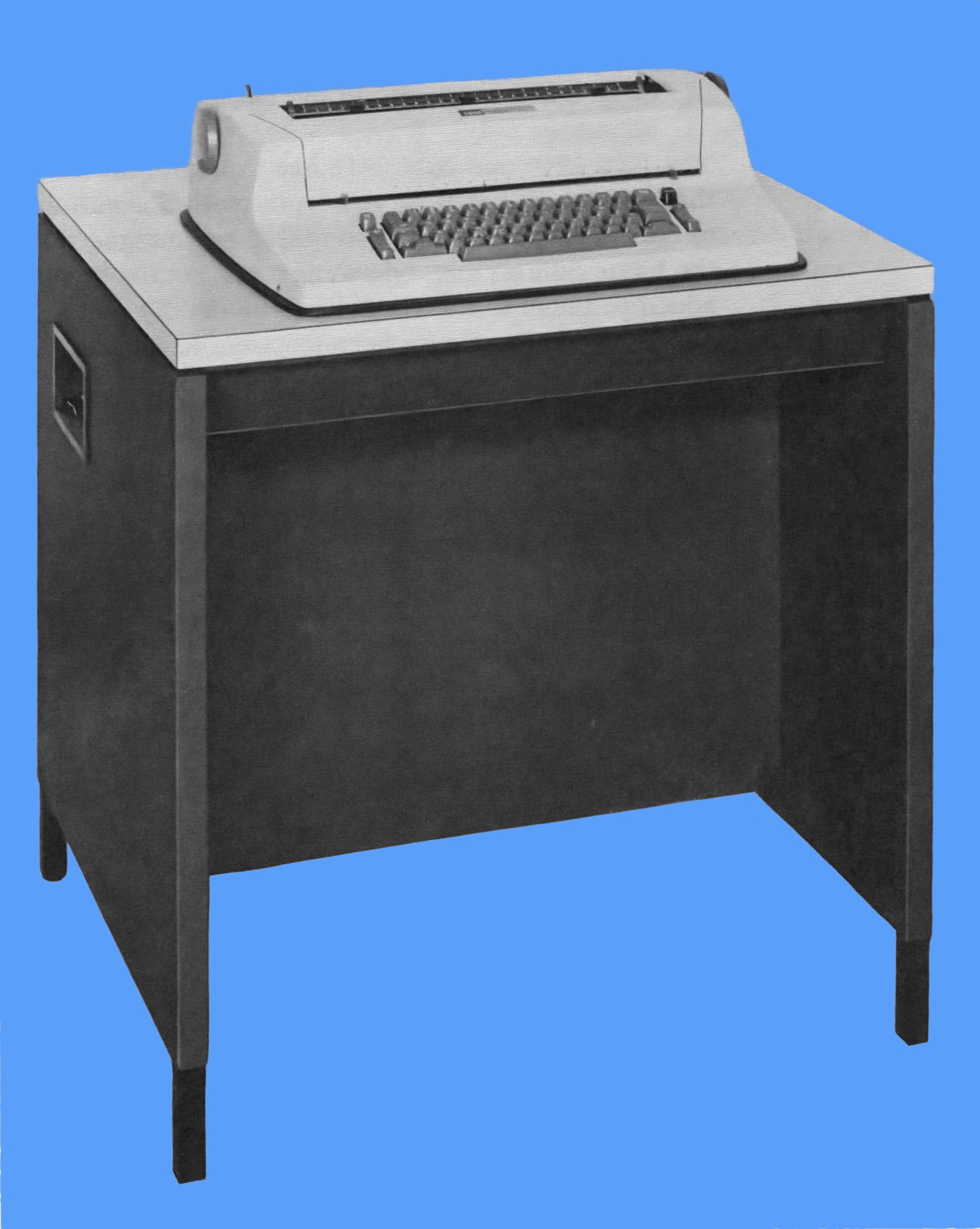
(How can there not be a modern high-resolution picture of this terminal online? I created this one based on a manual for the terminal. I rotated the picture, smoothed it, and added a blue background.)
There are obvious visual similarities:
- similar, but smaller desk without drawers
- use of an I/O typewriter
The IBM I/O typewriter obviously underlies the 2741 as well as the MT/ST. By some accounts, the I/O development started even before the original Selectric reached the market in 1961.
The 2741 includes SLT-based electronics in its desk. So no relays here (the original MT/ST remains an outlier), and no separate console. From this point of view, it is more similar to the MT/SC desk (see below).
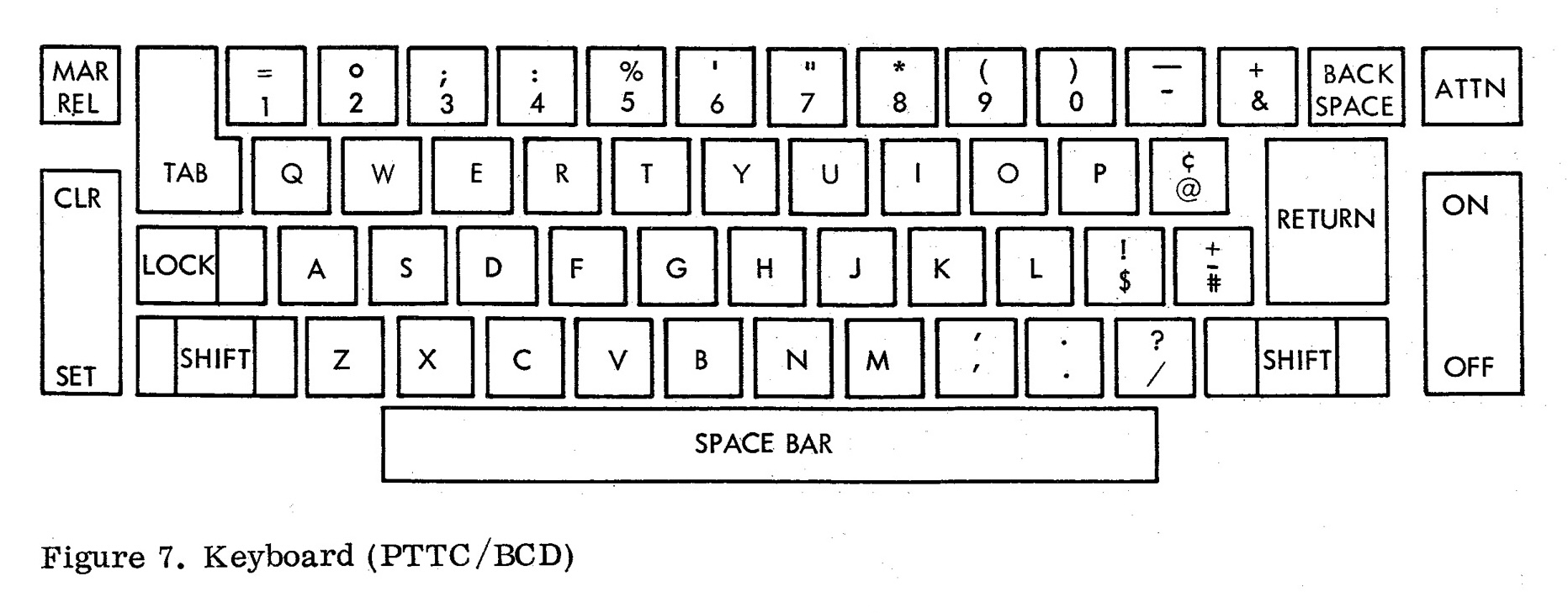
The keyboard has differences as well:
- The MT/ST and MT/SR have a large extra PX (“Prefix”) key to the left, while the 2741 doesn’t.
- The MT/ST has a “REV/CR” key, while the 2741 has an “ATTN” key.
- The layout of special characters appears different (for example location of “!”, “+”, etc.)
- The 2741 used a serial RS-232 connection, while the MT/ST’s connector to the console is entirely proprietary.
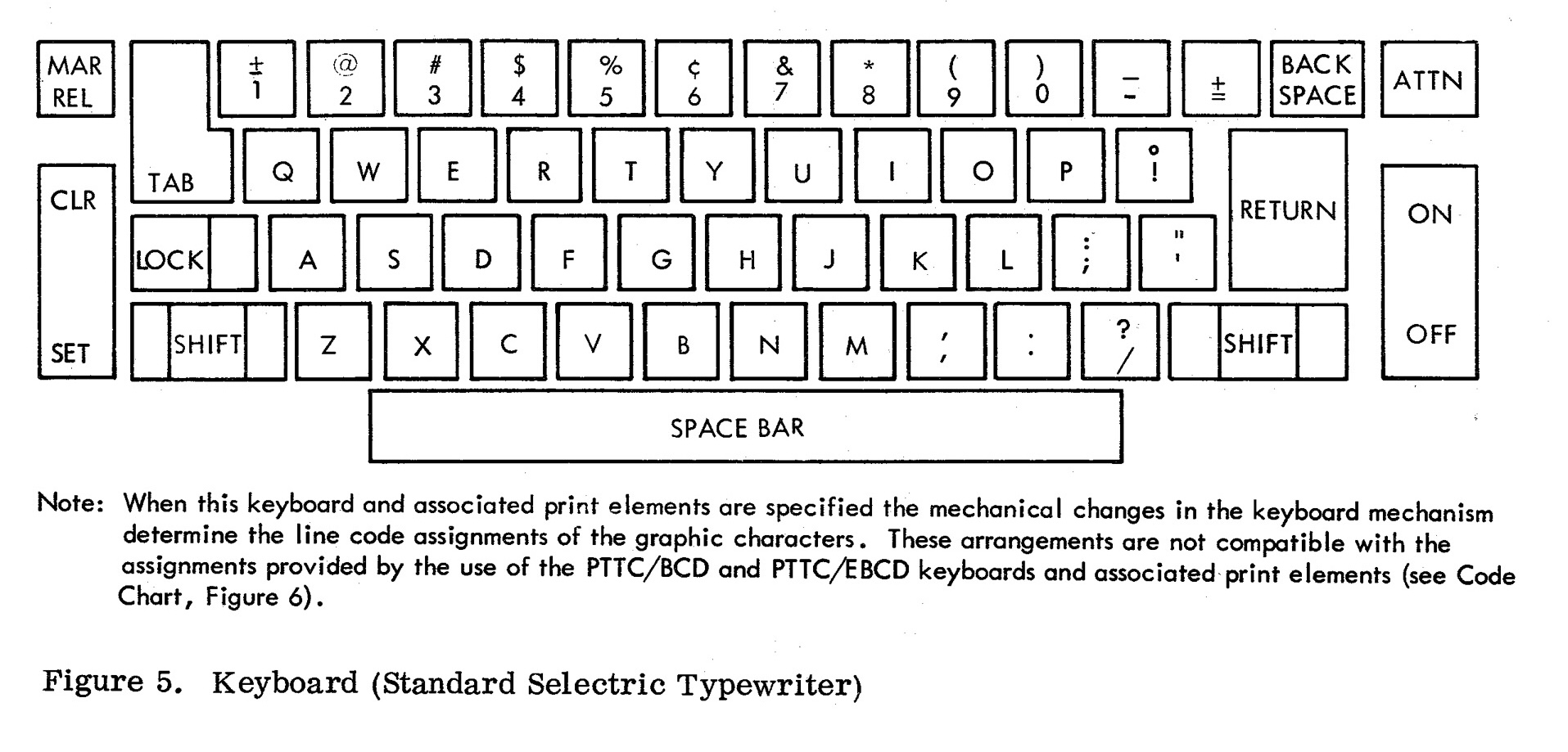
IBM documentation says that two types of keyboard/type elements could be ordered:
- standard Selectric typewriter (correspondence)
- PTTC/BCD or PTTC/EBCD
But while their documented Selectric layout appears to match the Selectric I’s layout, it is different from the MT/SR’s, which, as we have seen in part 1, matches the Composer layout.
The “Development” article mentions that:
Many of the memory circuits and array components were selected from those used in existing products such as the IBM 2740 Buffer Terminal. Many of the memory circuits operate from logic-level inputs, so that no well-defined interface is needed between memory and logic.
It could be that the memory module, in particular, is also present on the 2740. If anyone is able to confirm or infirm that, it would be great to let me know.
Restoration plan
I was incredibly lucky to have the visit of CuriousMarc and Ken Shirriff to have a look at the system. We talked a lot about it and what will need to be done to get it working again. They think that there is good hope to get it working, including the electronics, which they have the skills to analyze and repair, and the tape drives - the two major areas of the system that I feel the least comfortable with.
So I have put together a very simple restoration plan:
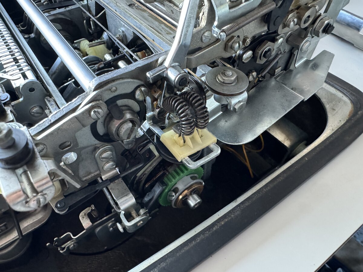
- Clean and fix the input (MT/SR) typewriter
flush the old greasereplace the tab pulley- relubricate
- check operations with the hand cycle tool
- separately power up the typewriter
- Clean and fix the input tape console
- flush the old grease
- relubricate
- check operations manually
- check the PSU voltages
- try to power the system up
- Clean and fix the Composer
- flush the old grease
- relubricate
- check operations with the hand cycle tool
- power up the Composer
- Tackle the MT/SC electronics
- …profit!
I feel that I can reasonably start looking a the typewriters, since I have some experience with that. The tape consoles are not extraordinary complex either. Mechanically, they obviously need to be cleaned, flushed of old congealed grease, and then probably relubricated.
I will leave the MT/ST electronics for last, as that is the most challenging project, probably. Well, it could be that everything “just works”, who knows! But for now I have to assume that restoring the entire system will be a large undertaking with some surprises along the way.
Some initial work
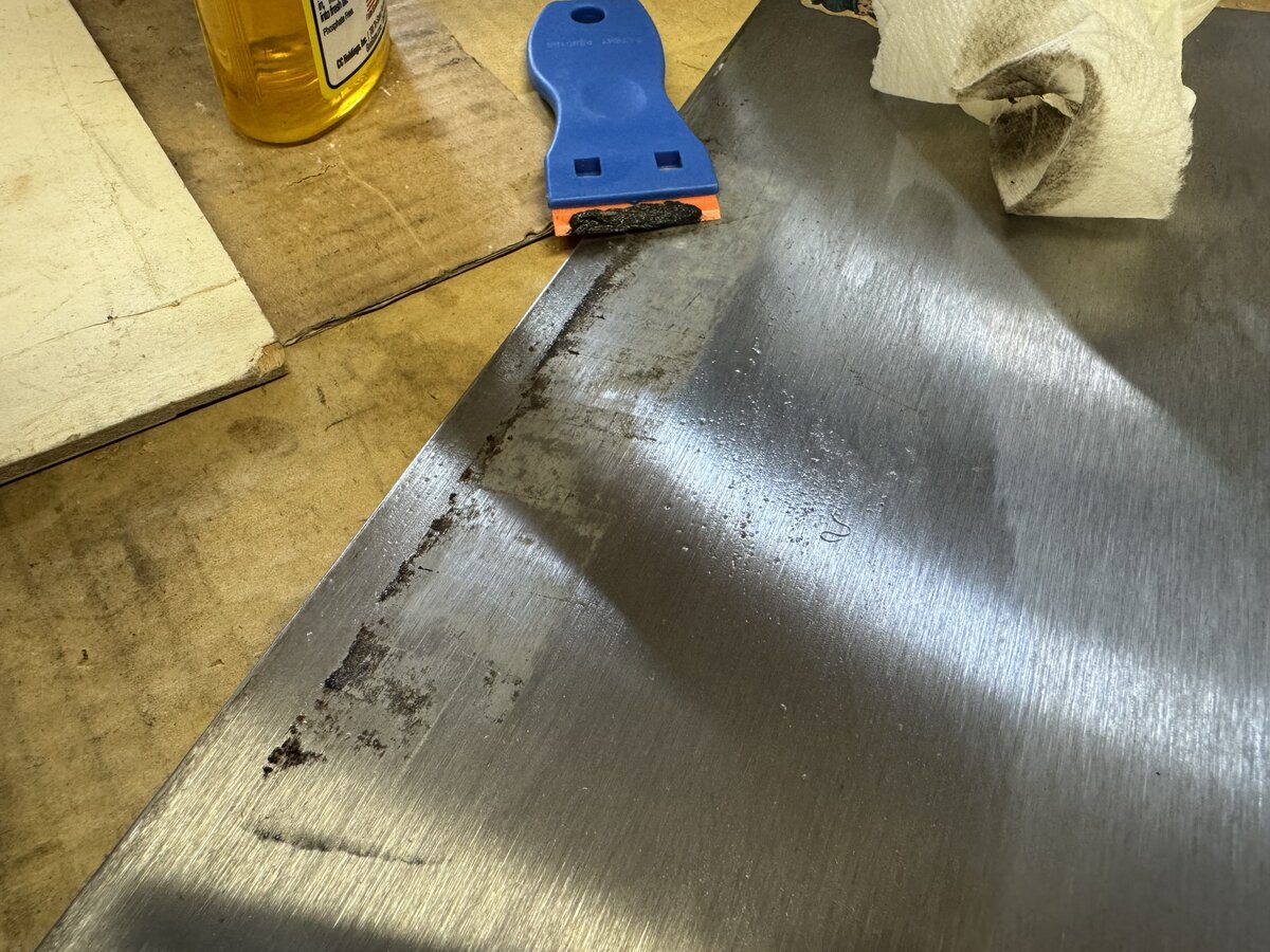
As of June 2024, I have already started work on the MT/SR typewriter. I have flushed the MT/SR typewriter’s old grease and dirt, and I replaced the broken tab pulley. However, the machine seems to be stuck mid-cycle, and I will have to investigate more before I even attempt to power it up.
I have also started removing the sound-deadening foam from the tape units, and otherwise cleaning the tape units enclosures.
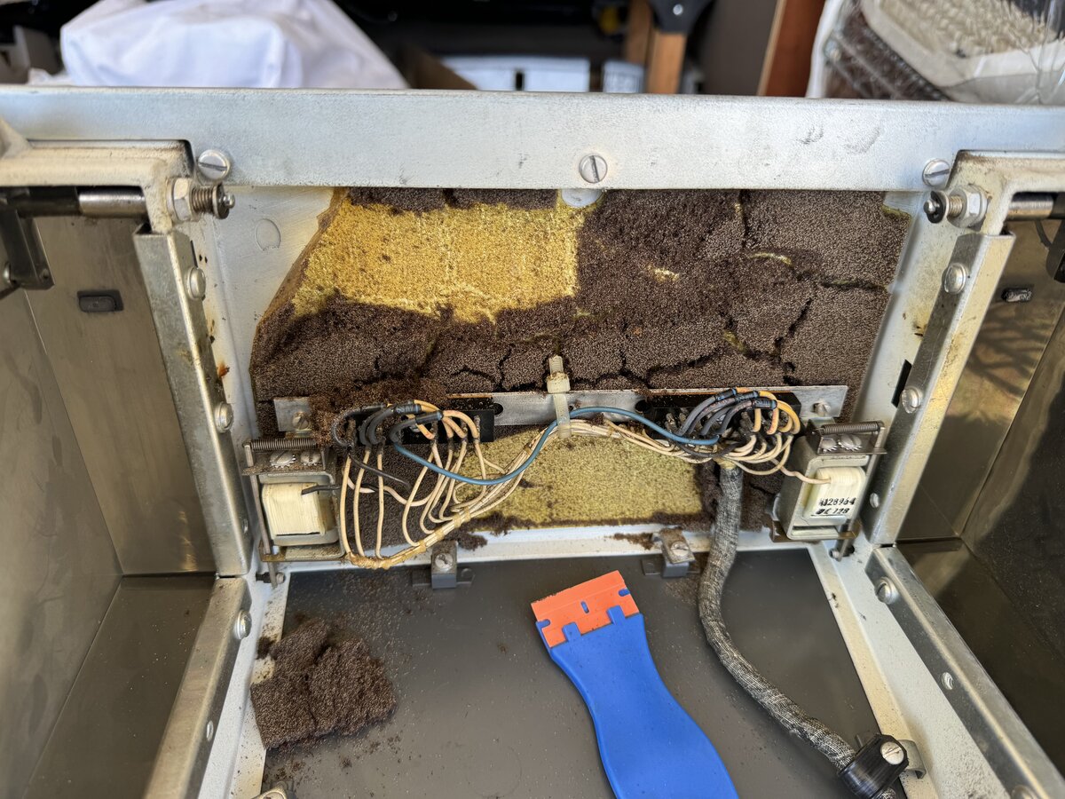
I removed the foam from the MT/SR typewriter, and the electronics cage as well.
I cleaned the MT/SR’s document holder, the binders, and the Composer type elements and box. Unfortunately, I didn’t manage to get rid of the rat urine smell on the papers. I even tried to use an ozone machine, but I am not sure that had an actual effect.
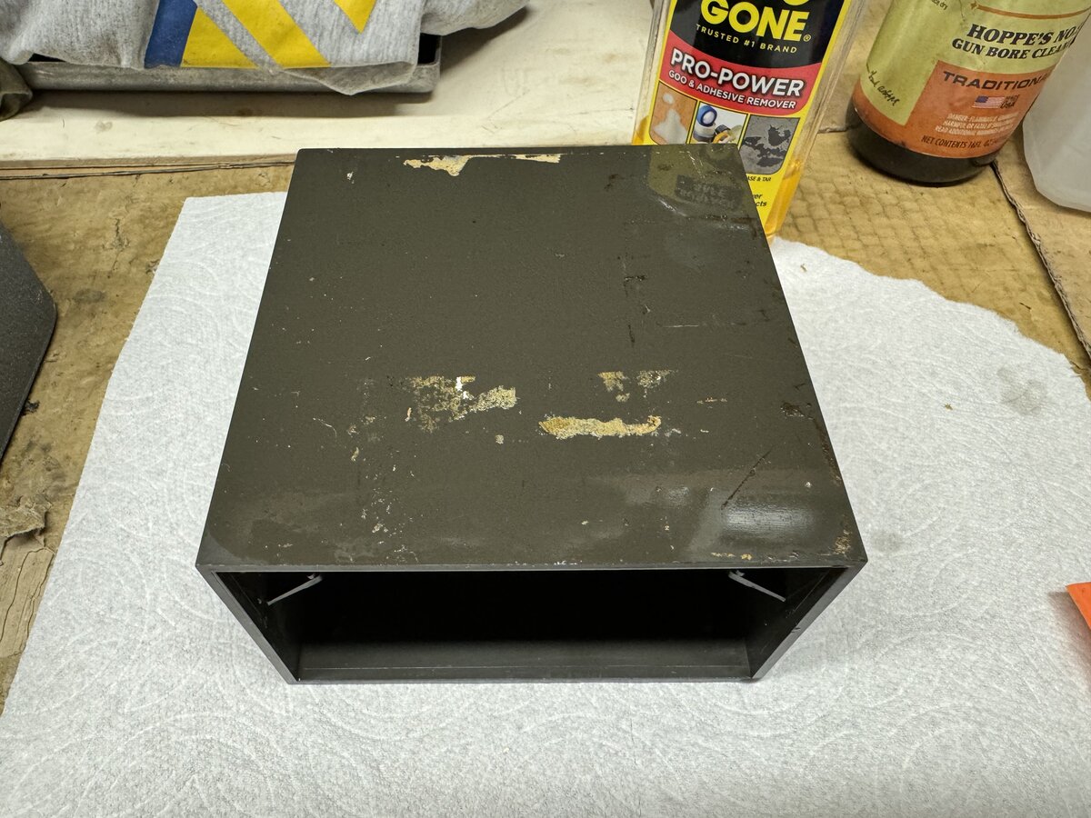
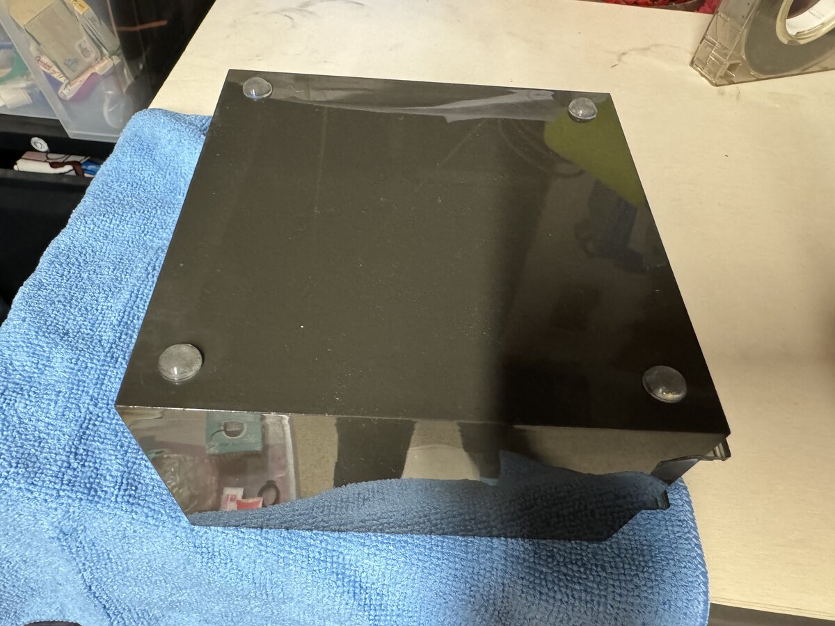
The box also now has new feet.
I already had a BORA base, which I had used for one of my ASR-33 terminals. I bought a second one, this time with a metal frame.
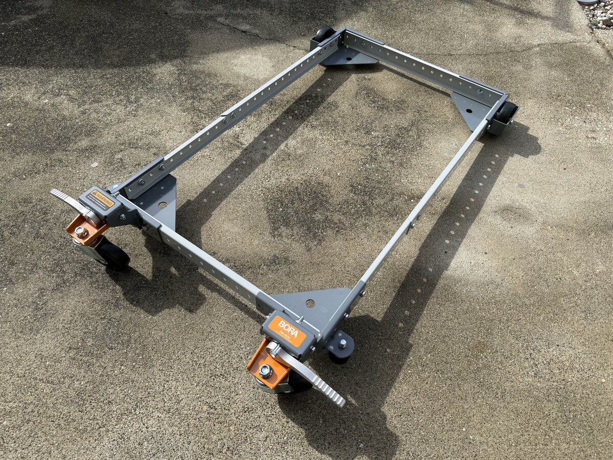
You can see the MT/SR tape console on its base here:
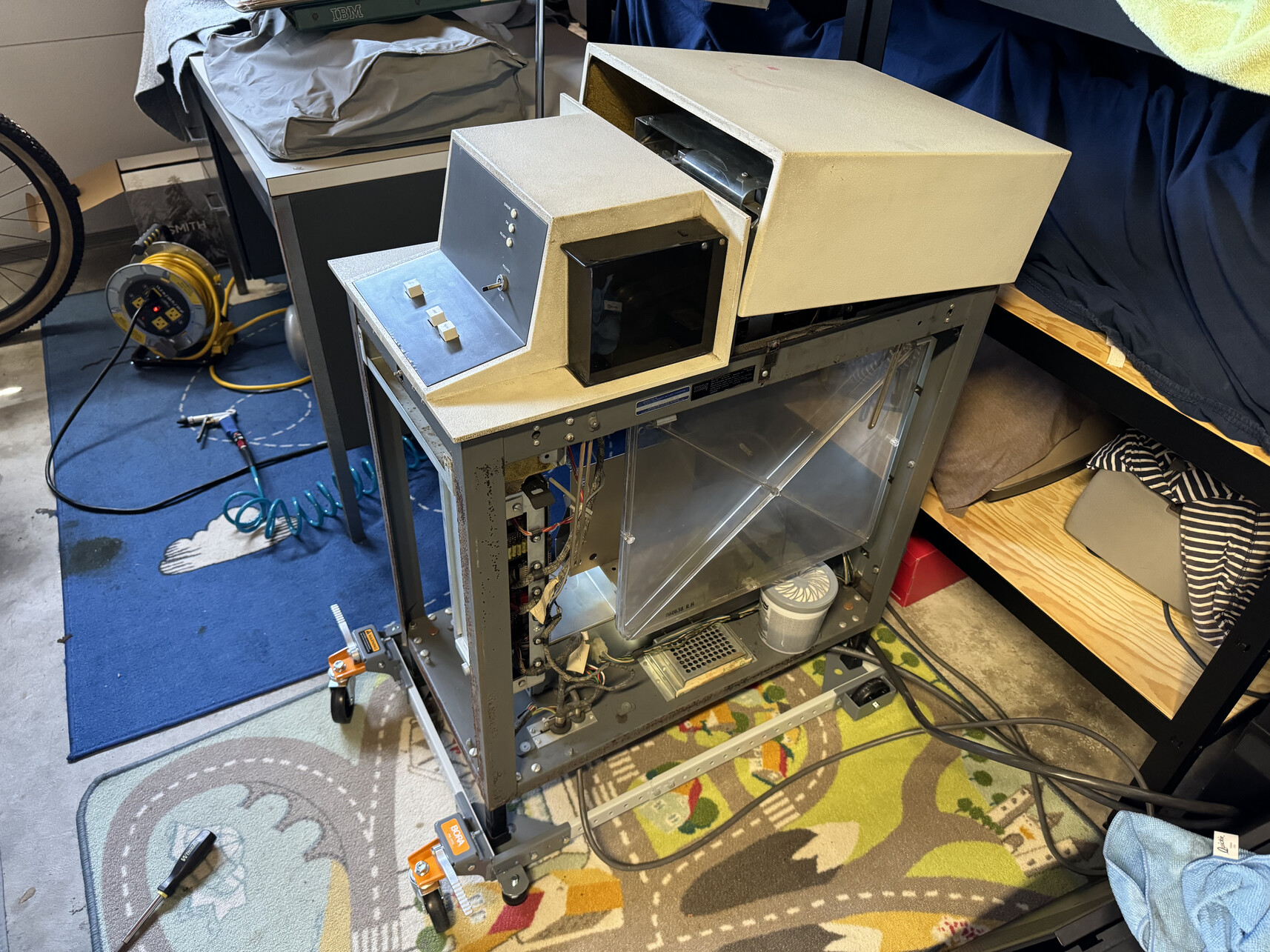
These bases are convenient to move things around. I also put new rubber feet on the tape console. I wish I could put the desks on wheels as well, as they are extremely heavy.
Temporary conclusion
In this post, I placed the IBM MT/SC in its context, described its various parts, and started digging into the details of the MT/SC instance that I acquired. The system received a basic cleaning, and is stored in reasonably good conditions. It has been fairly extensively photographically documented. Its unique documentation has been scanned for posterity. Finally, I outlined a restoration plan, which I hope will eventually unfold.
References
- Photo albums
- TWDB
Comments powered by Disqus.