
Introduction
I previously wrote about my IBM Memory Typewriter. In this post, I describe the initial troubleshooting and cleaning of the machine. I am also publishing the second installment at the same time. This is still a work in progress as of October 2021.
The covers
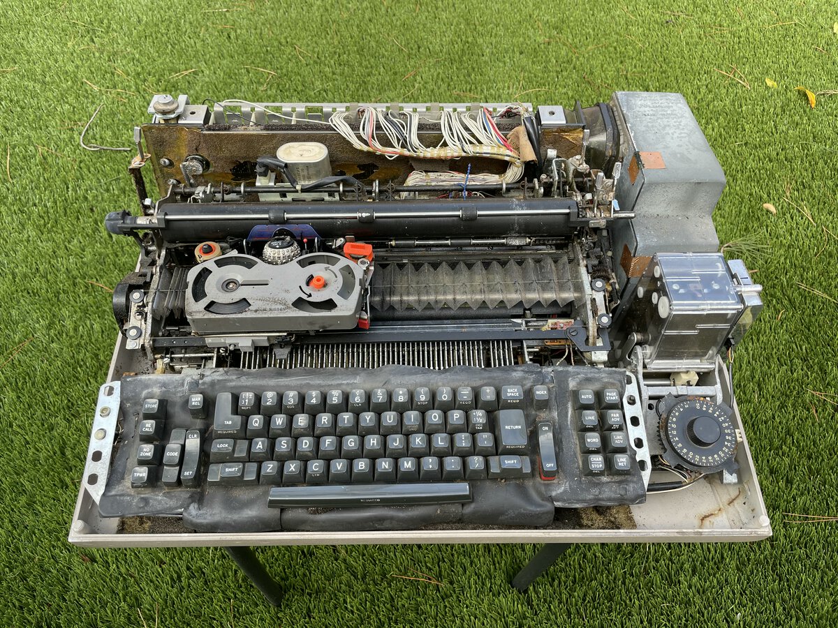
The machine has “top” and “center” covers, as the service manual calls them. They have to be removed to access the inside of the machine. The covers were not fully closed when I got the machine. I don’t know yet if they are missing screws or latches. But in any case the inside was filthy!
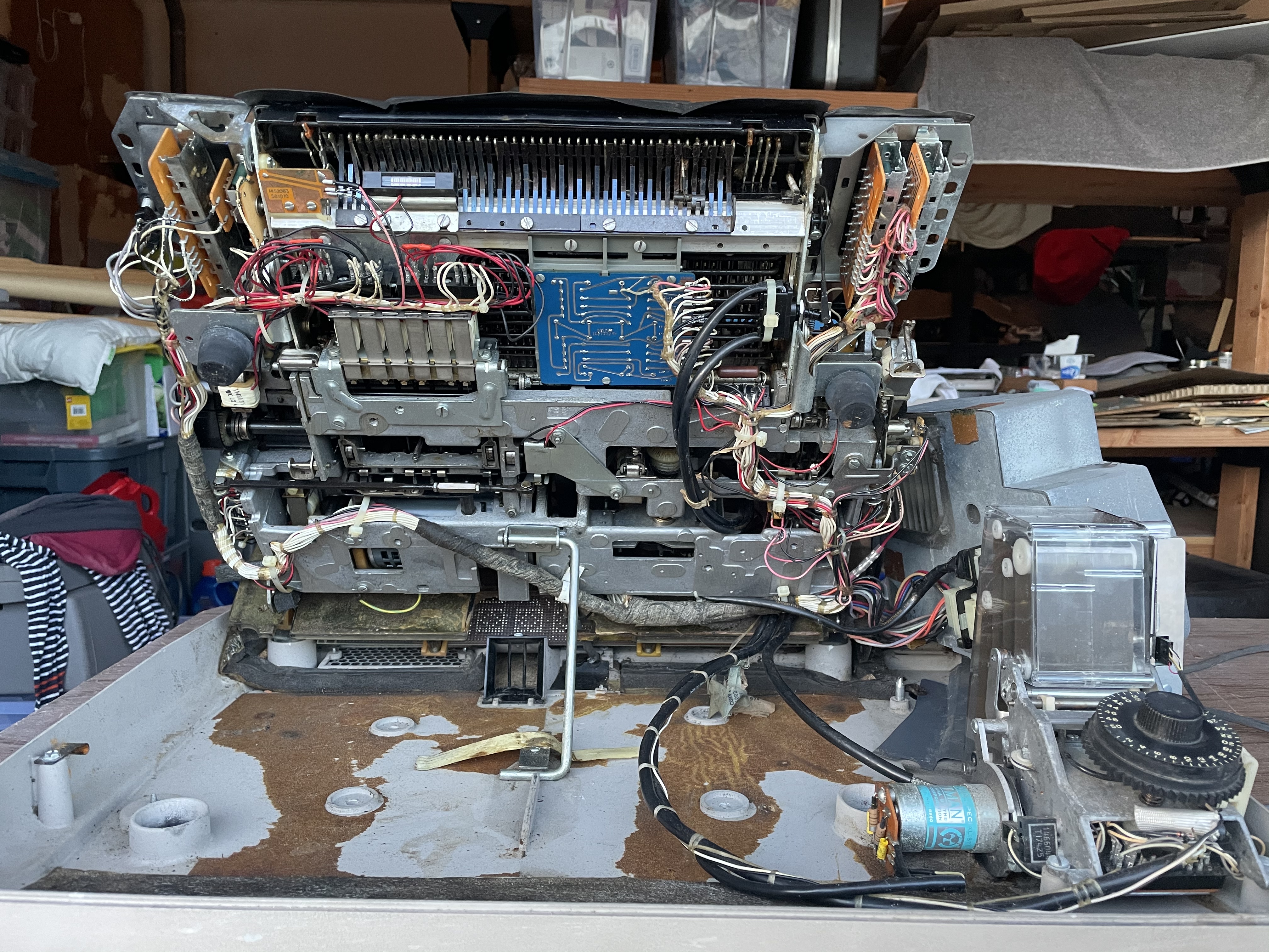
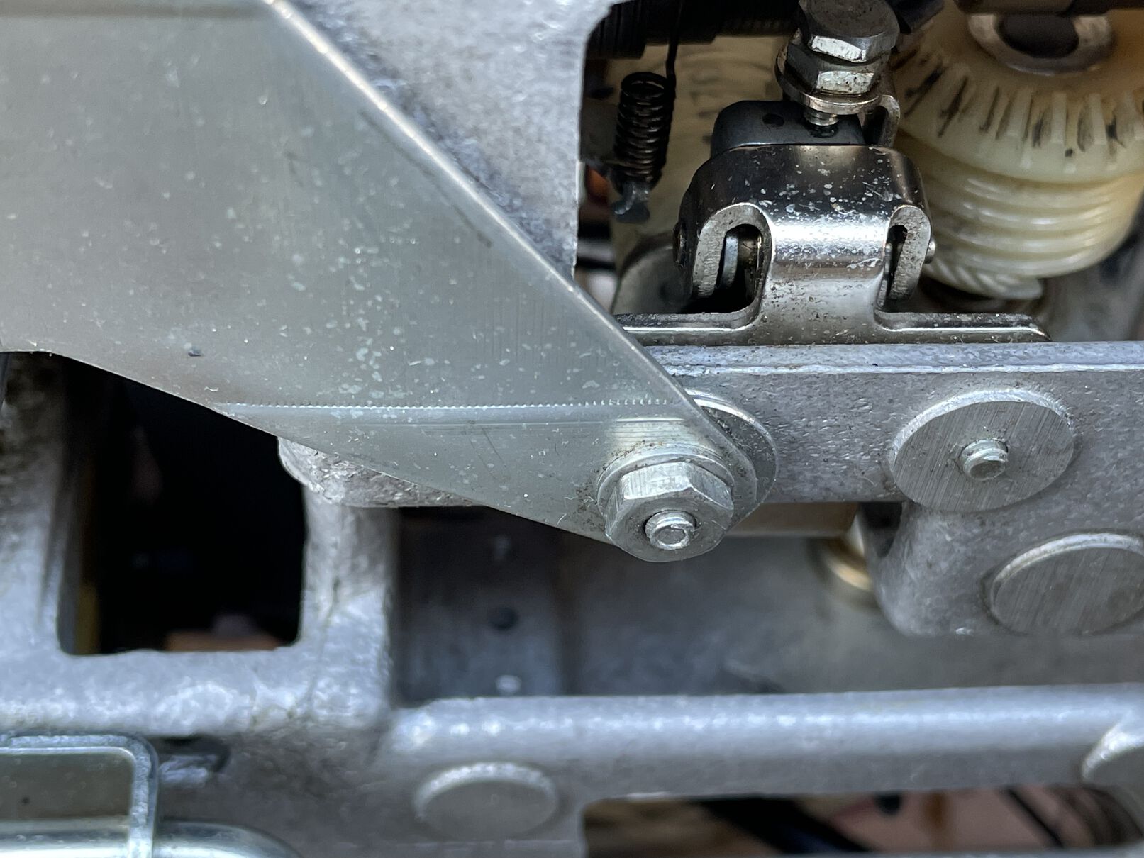
The tilt support
Unlike the regular Selectric, you don’t take the machine fully out of the case to service it. Instead, it is equipped with what I called a kickstand, and which the service manual calls “tilt support”. This allows lifting the main body of the machine so you can access underneath. This doesn’t include the power supply and the tape loop, which are separately attached to the bottom of the case.
I wasn’t sure how hard I should push up the body of the machine, or where to hold it while doing so. The machine weighs 57.8 lbs (26.2 kg) and the main body is a good part of that weight. I pushed slightly, then figured I needed to unscrew a metal part underneath (called the “retainer” in the manual) before putting the stand up and then screw again to secure the kickstand. This way you won’t get your head or fingers crushed if it fails!
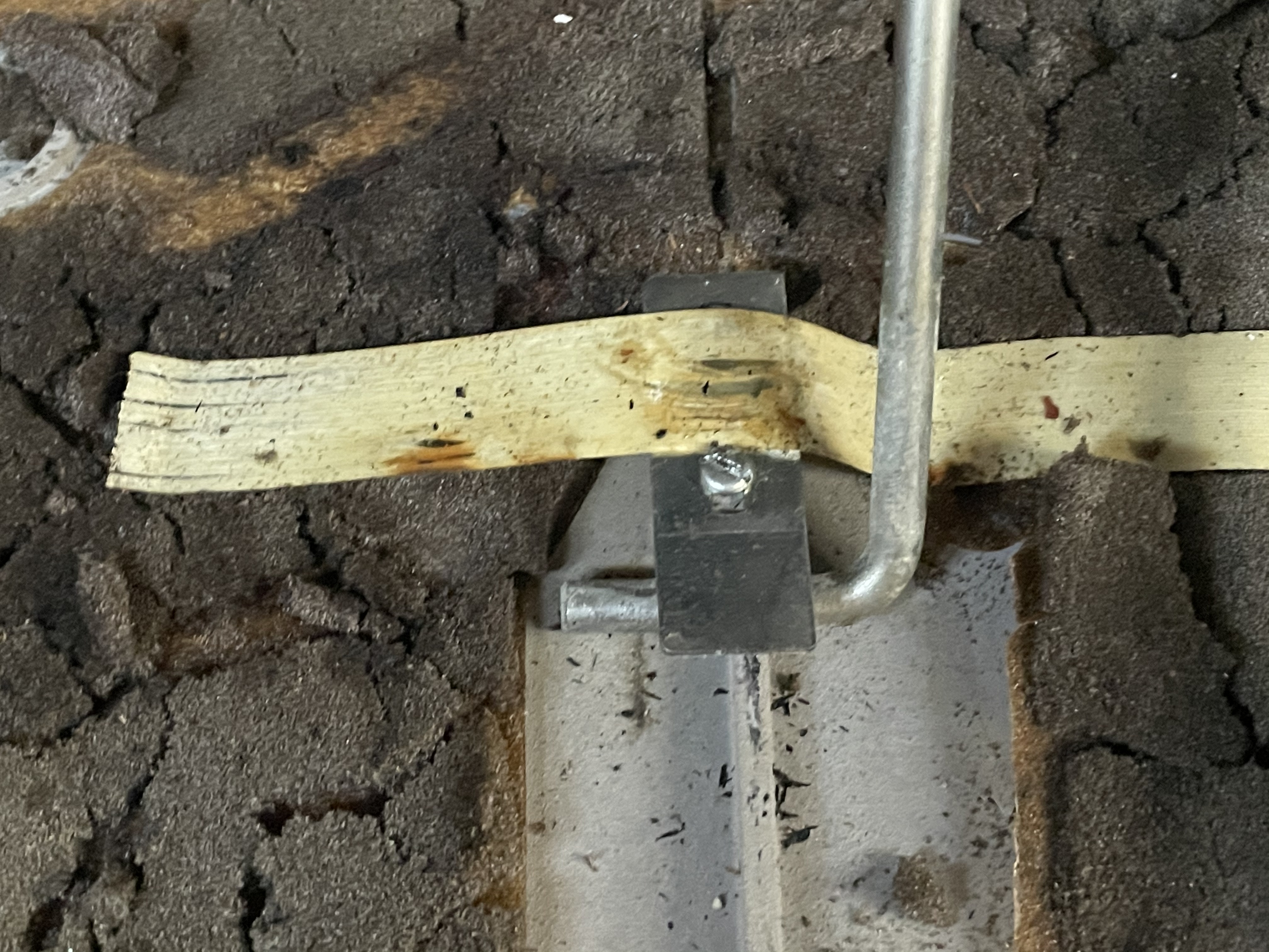
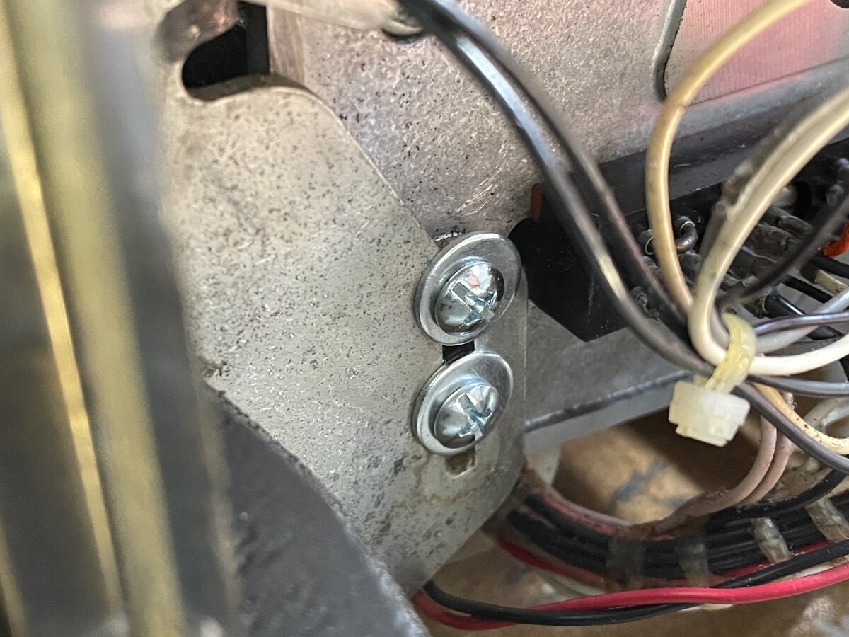
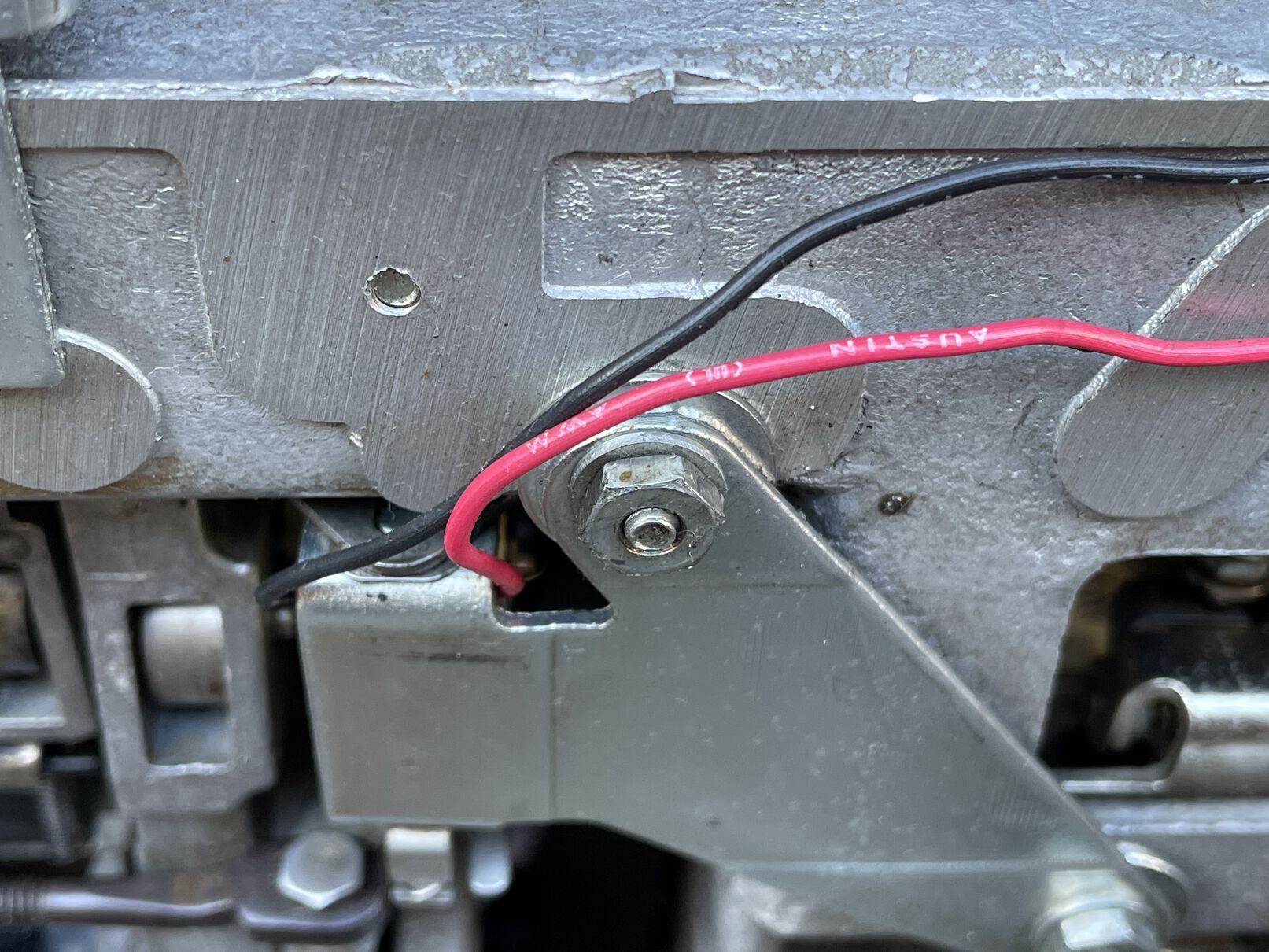
The process was harder than it should have been, because the left hinge was missing 2 screws. I found them at the bottom of the machine, but they didn’t hold properly. I put a temporary fix in place so that the body would rest on the hinge.
Initial cleaning
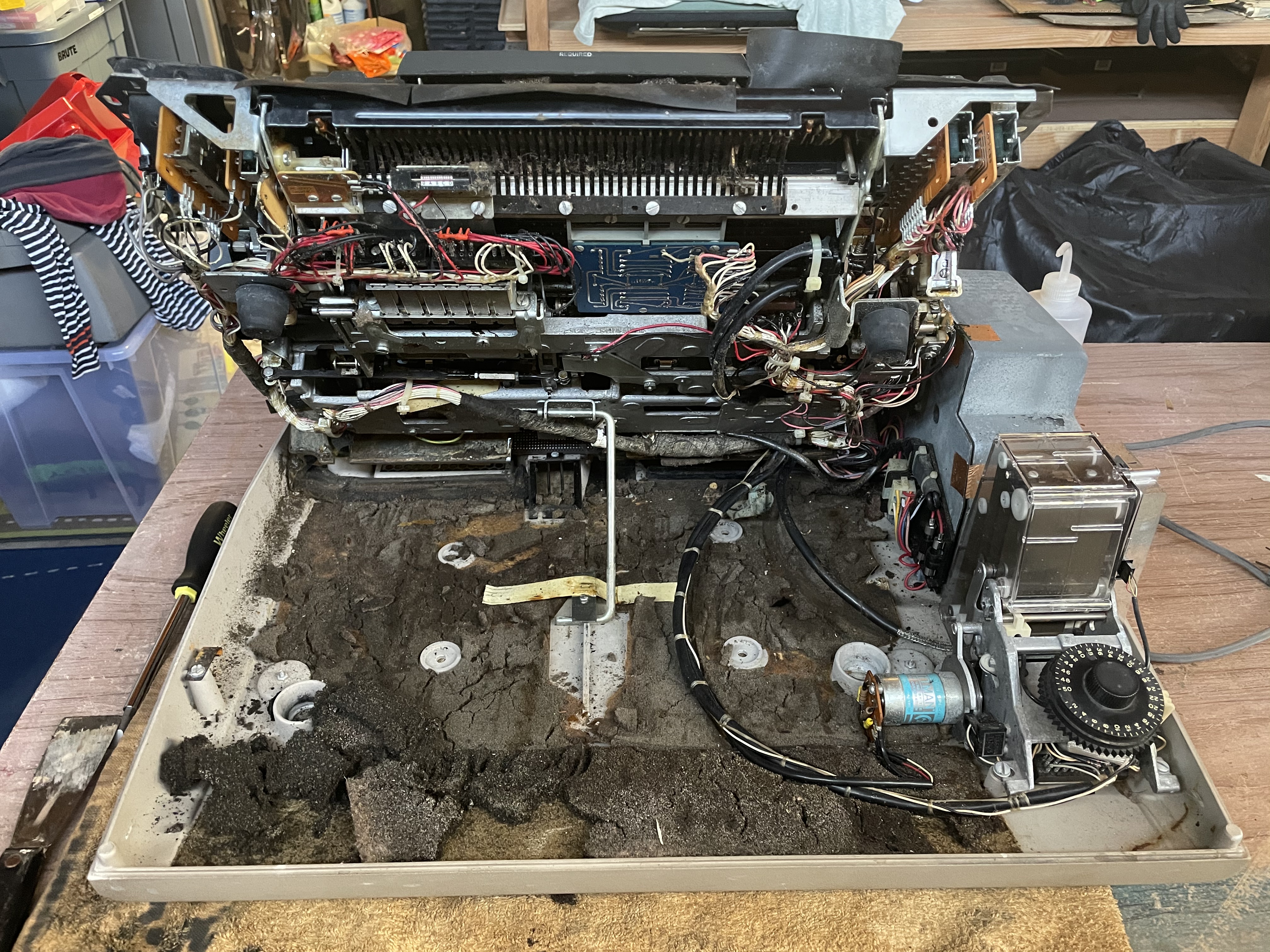
I scraped, brushed and vacuumed the disintegrated foam. I also moved the power supply to the side for easier cleaning. It was held in place with a single screw. Then I also used an air compressor to blow out dust.
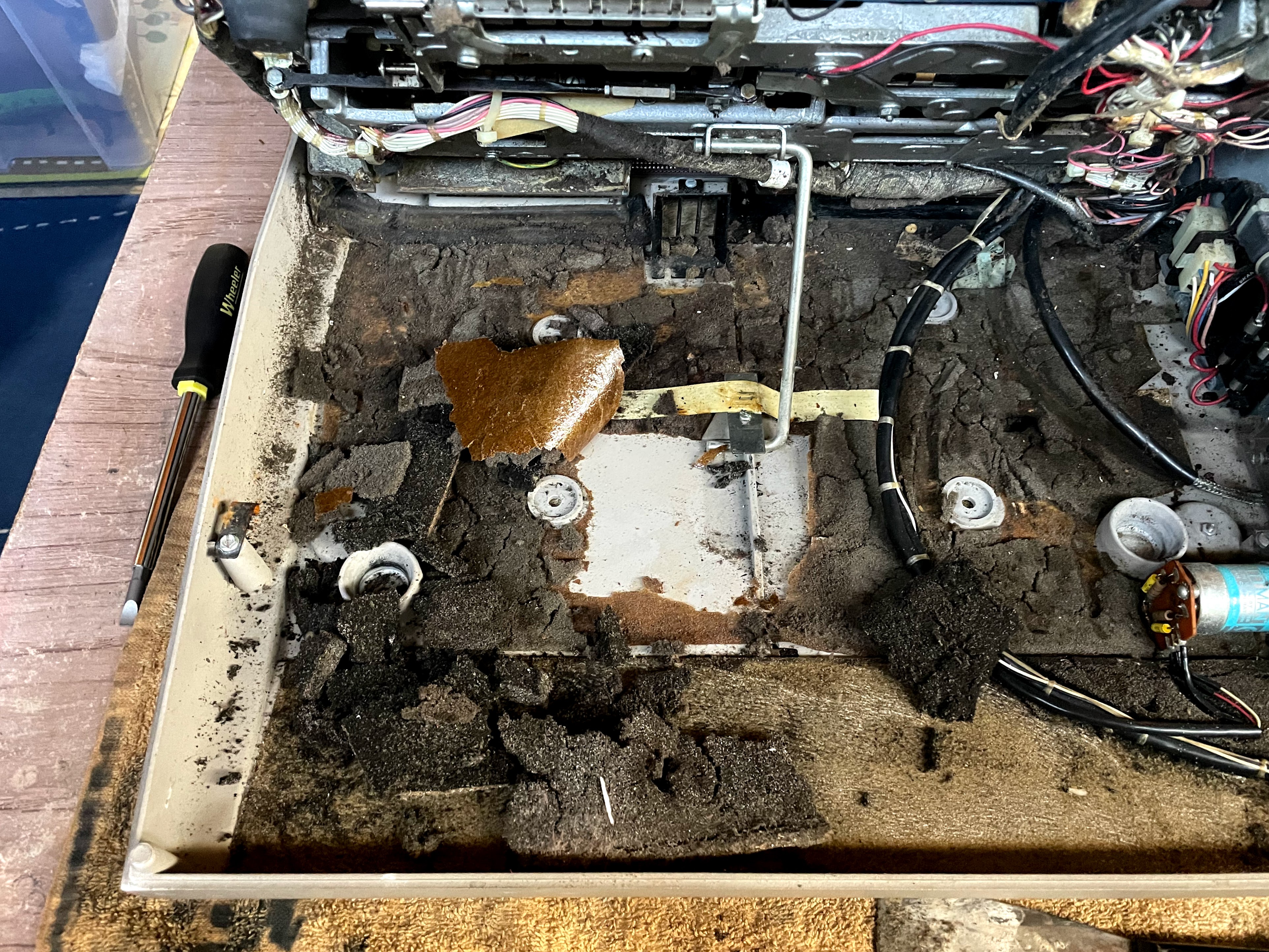
The machine was in much better shape after these initial steps!
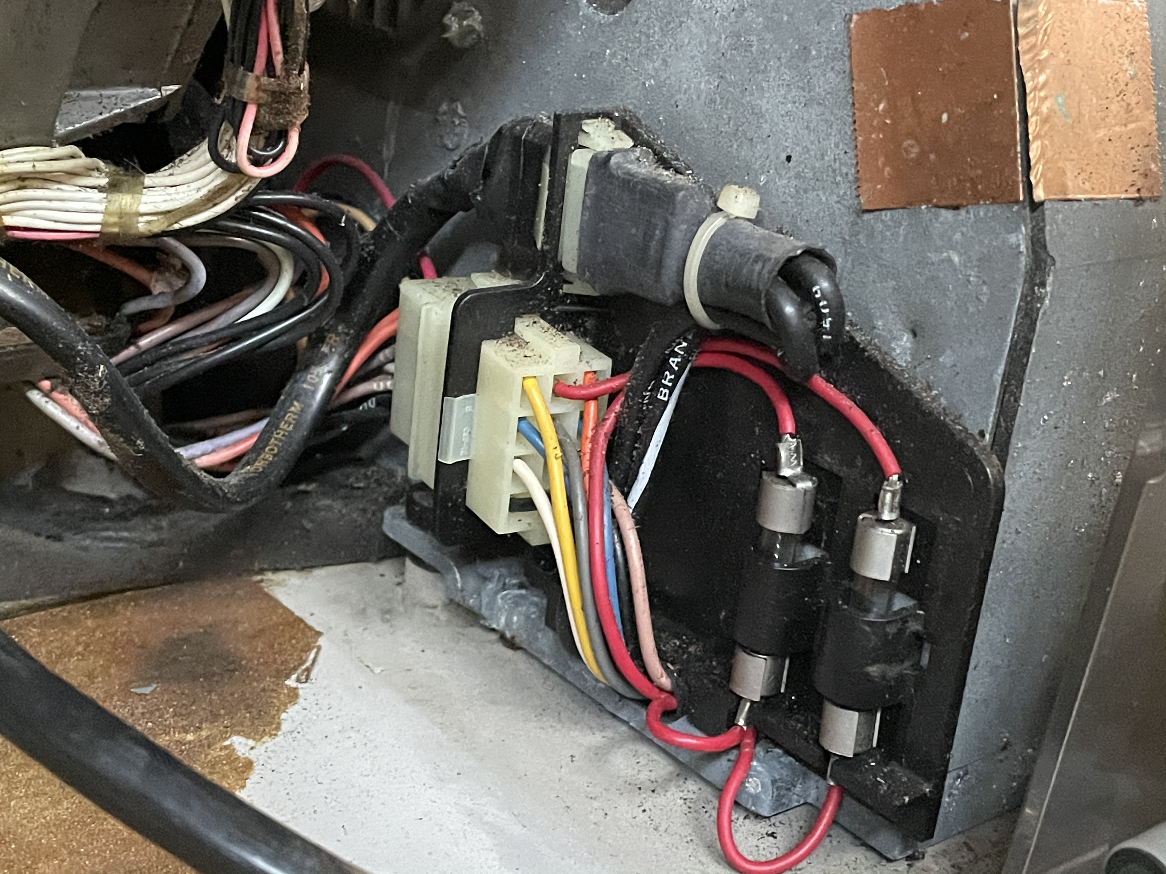
The power supply
Before anything else, I wanted to test the power supply separately.
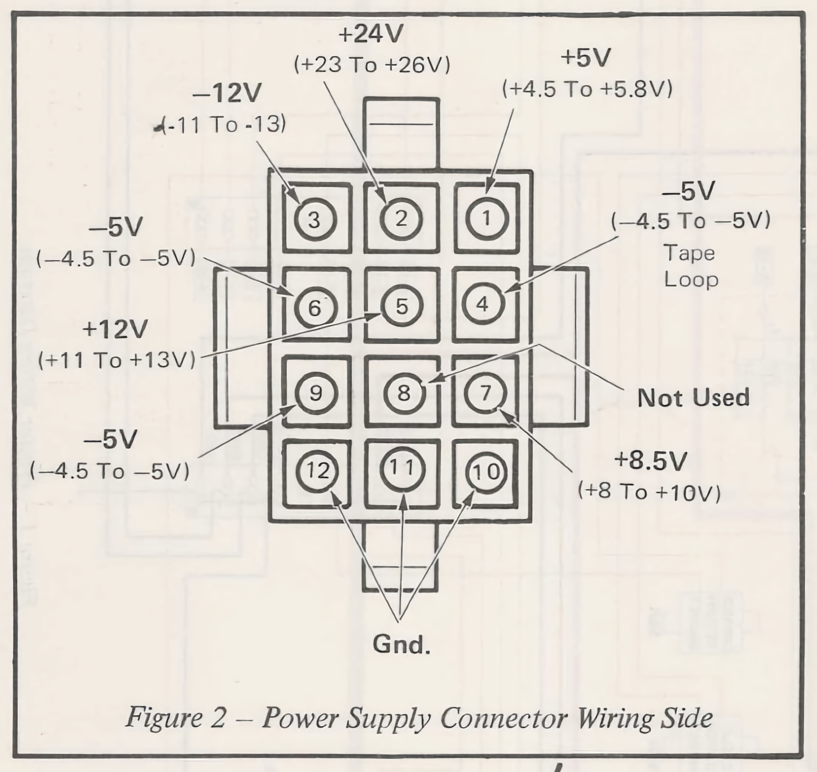
Thanks to the service manual, all the expected voltages are known. They are:
- +24V
- -12V
- +5V
- -5V
- -5V for the tape loop
- +8.5V
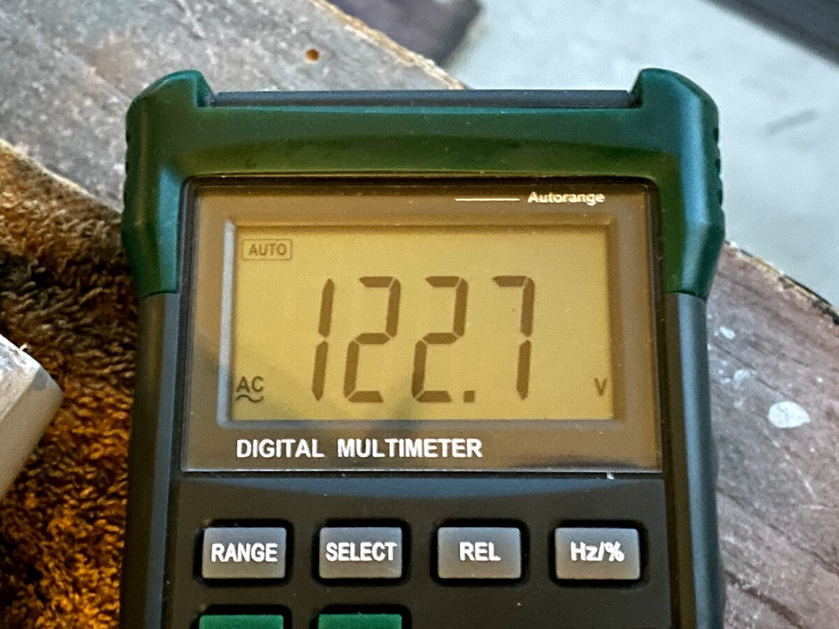
I disconnected the AC and DC connectors, then opened the power supply to clean it a little and blow compressed air. It was a little dirty but otherwise looking good. When I tested it, all the voltages checked!
I also checked the AC connector on the AC motor, and it was good.
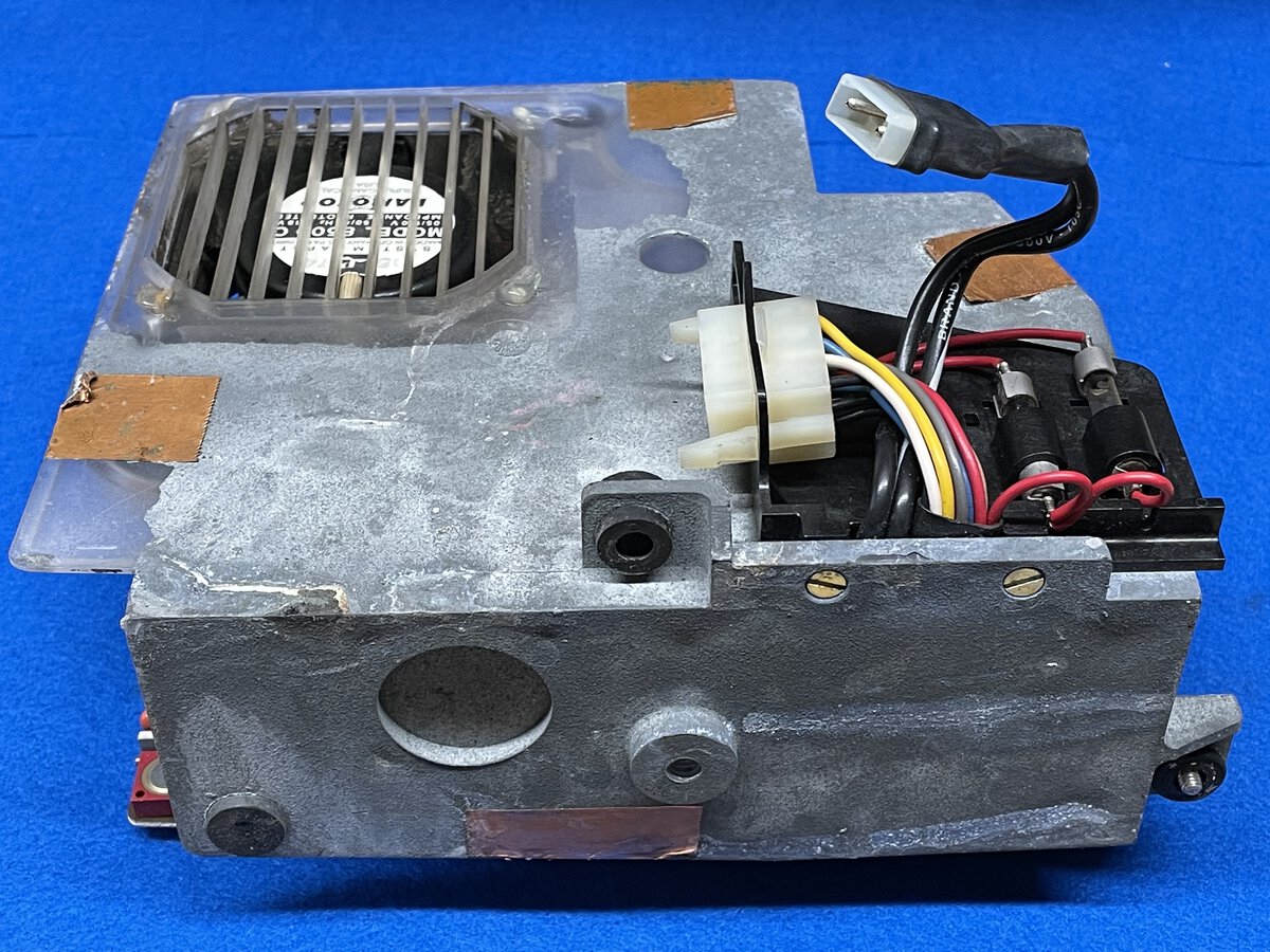
I later took better pictures of the power supply. The enclosure is made of some sort of plastic covered with a sort of gray (conductive?) crinkle paint.
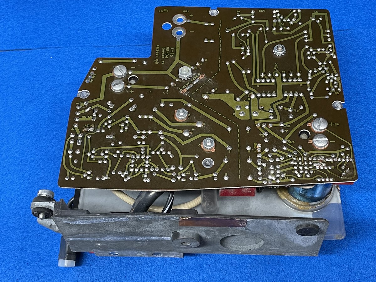
This is the bottom of the PCB, with a clearly indicated separation between the high-voltage and low-voltage areas.
This power supply appears to be complex, and I suspect it contains some pretty custom IBM chips as well. This is probably due to the large number of different voltages required.
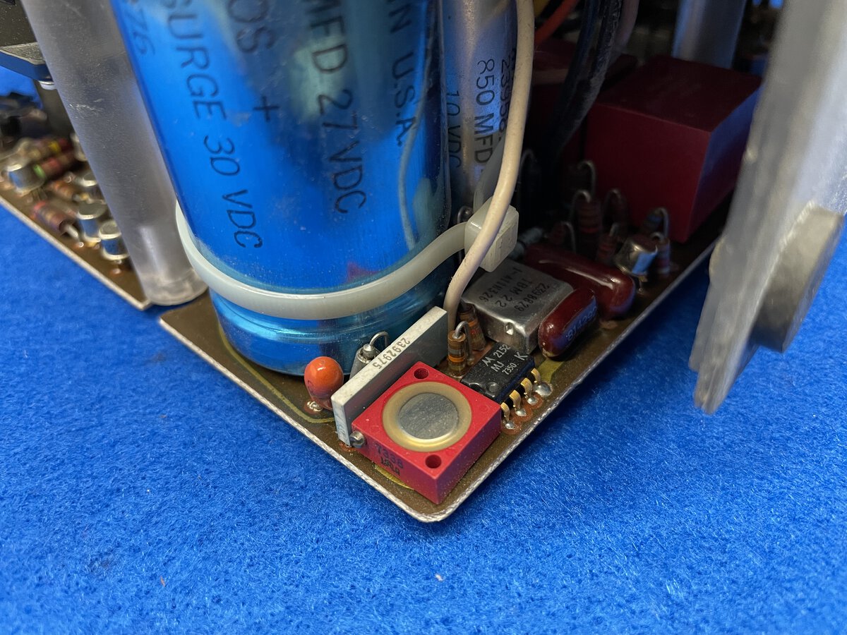
While taking pictures, I grabbed the power supply in the wrong way, and bent one of the transistors. I bent it back a little, and I hope this is not permanent damage, but I will check the voltages again before connecting power. Luckily, if it’s just a transistor, there should be an available replacement in case there is a problem with it.
The AC motor
The first obvious issue with the machine was that the AC motor didn’t run. This is the motor that runs all the mechanical functions of the machine, exactly like with a Selectric. I tried powering it up again and confirmed that it was stuck. Looking closely, I could tell that the motor was trying to rotate, but just couldn’t. So I had to try to figure out where things were stuck.
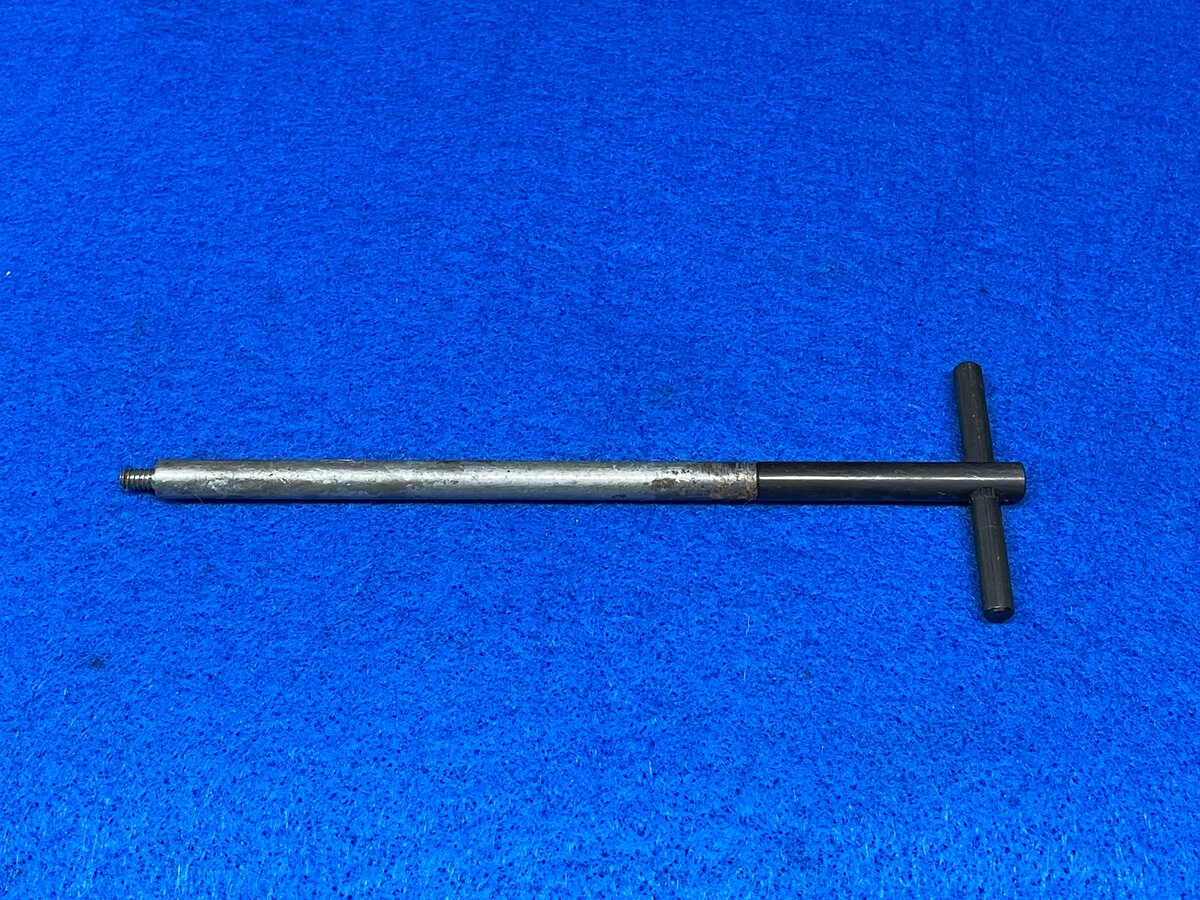
I acquired a hand cycle tool from Clark Hinson via eBay. These are newly-made versions of a standard IBM tool, which allows you to “cycle” the machine without the motor. This allows you to control and visually inspect everything that’s happening when the machine goes through a keyboard cycle.
The IBM Memory Typewriter has a built-in extension shaft to account for the wider size of the machine. This part was at the bottom of the machine when I found it, and someone online correctly pointed out its likely use.
You can’t turn too hard or the tool will break, so I had to be careful. Rotating by hand didn’t work at first. I applied mineral spirits on some parts that looked like they could be stuck. Still no progress. I also tried to help by trying to move other parts while using the hand cycle tool. Then I decided to power the machine on to get some help from the motor, while I used the hand cycle tool. And it worked! Things started to run reasonably smoothly!
I should say that I broke my first hand cycle tool. At a later time, I had the motor running with the tool still attached, and a piece of clothing caught it. The tool broke very quickly. Luckily I managed to get it out of the extension shaft.
Debugging the cycle clutch
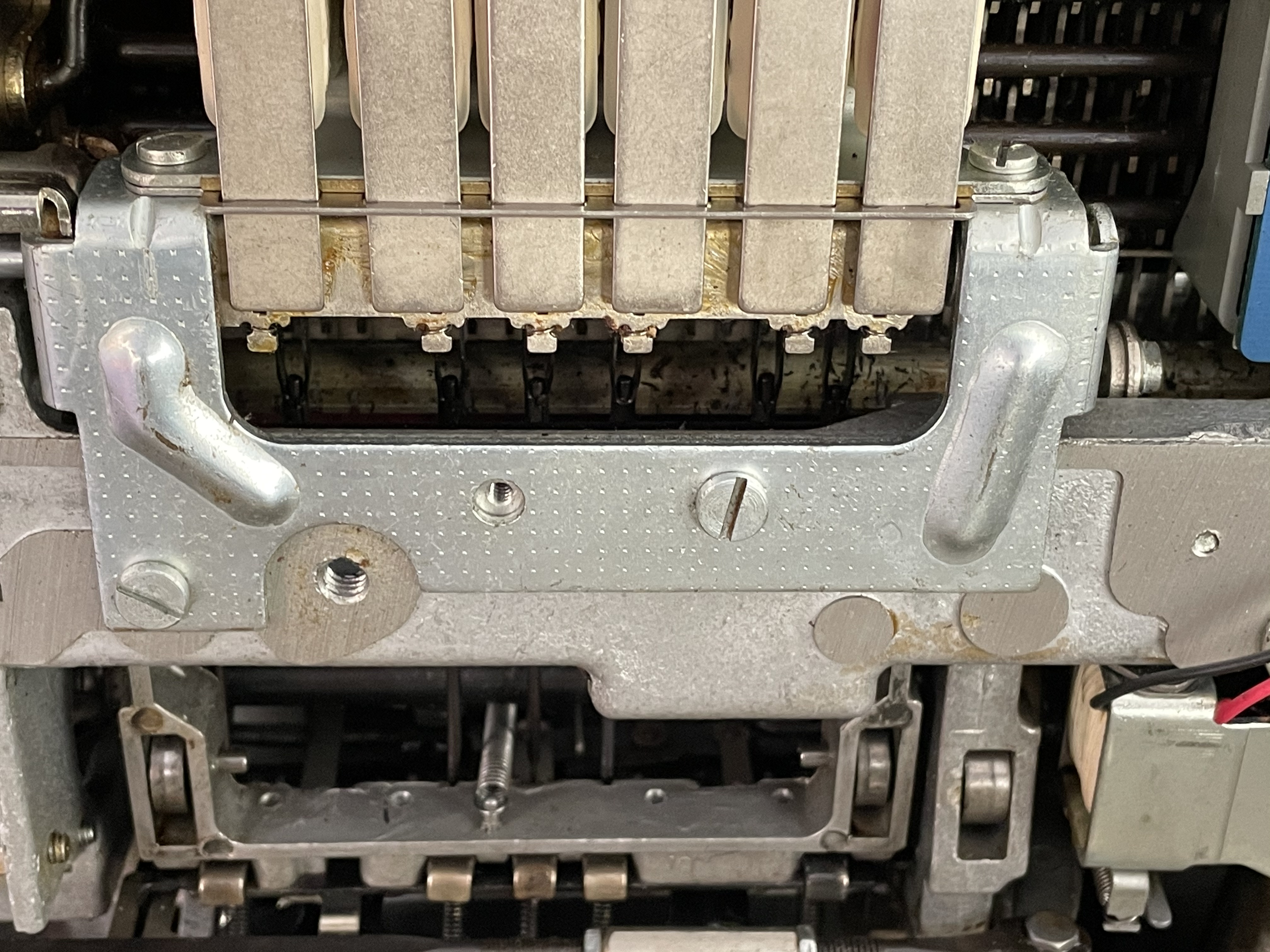
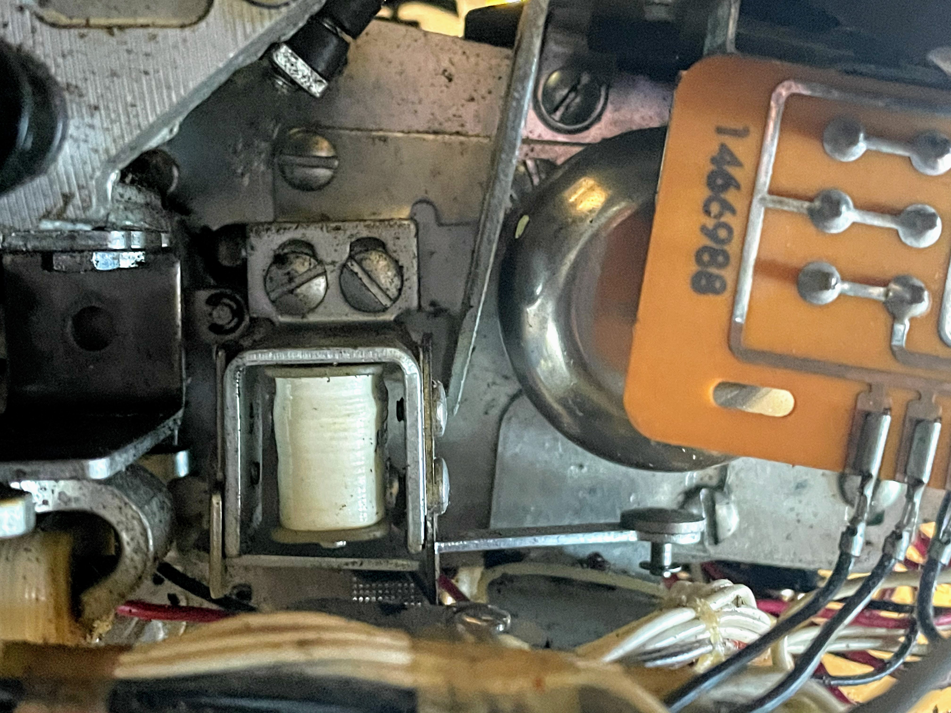
As things started moving and turning, I pressed a key. And to my delight, I saw the selection magnets, under the keyboard, activate! This meant that:
- The key selection was captured by the reed switches.
- The signals were sent to the planar.
- The planar was sending back signals to the magnets.
While this might not be very complex logic, it meant that the planar was working to some degree, which was fantastic news!
However, after that, nothing would happen. The magnets would remain selected and that was it.
What is supposed to happen is that the cycle clutch magnet is supposed to activate, which is supposed to get the machine to “cycle”: that’s the mechanical process whereby the cycle shaft turns and cause the type element to position itself to the right character, etc.
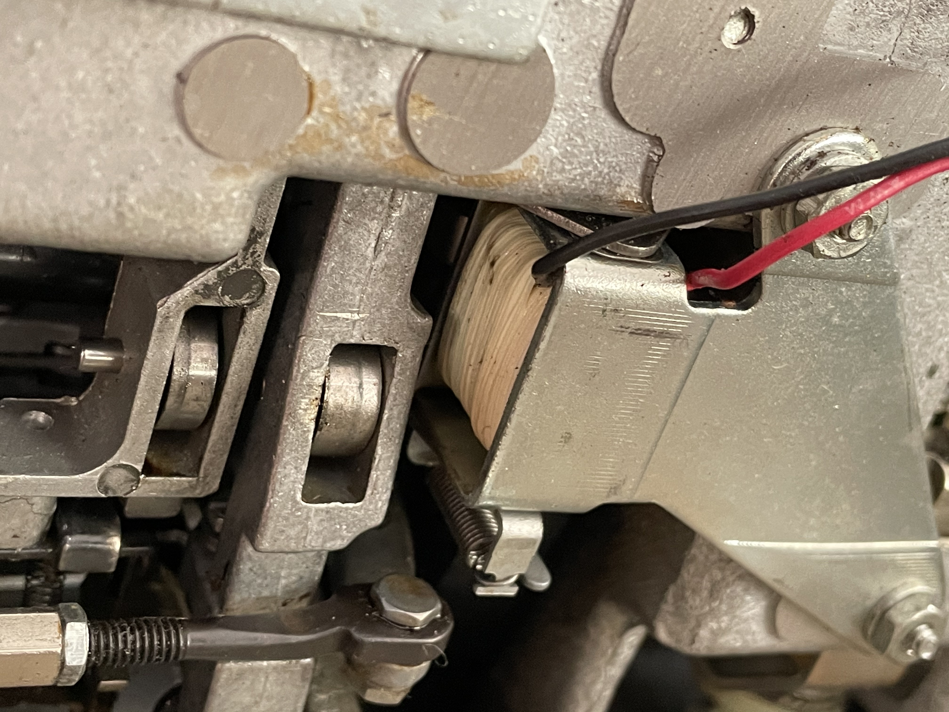
I took what was essentially a shot in the dark, and put two additional washers to adjust the distance of the plate that holds the cycle clutch magnet. And it worked! The cycle clutch started working fairly consistently!
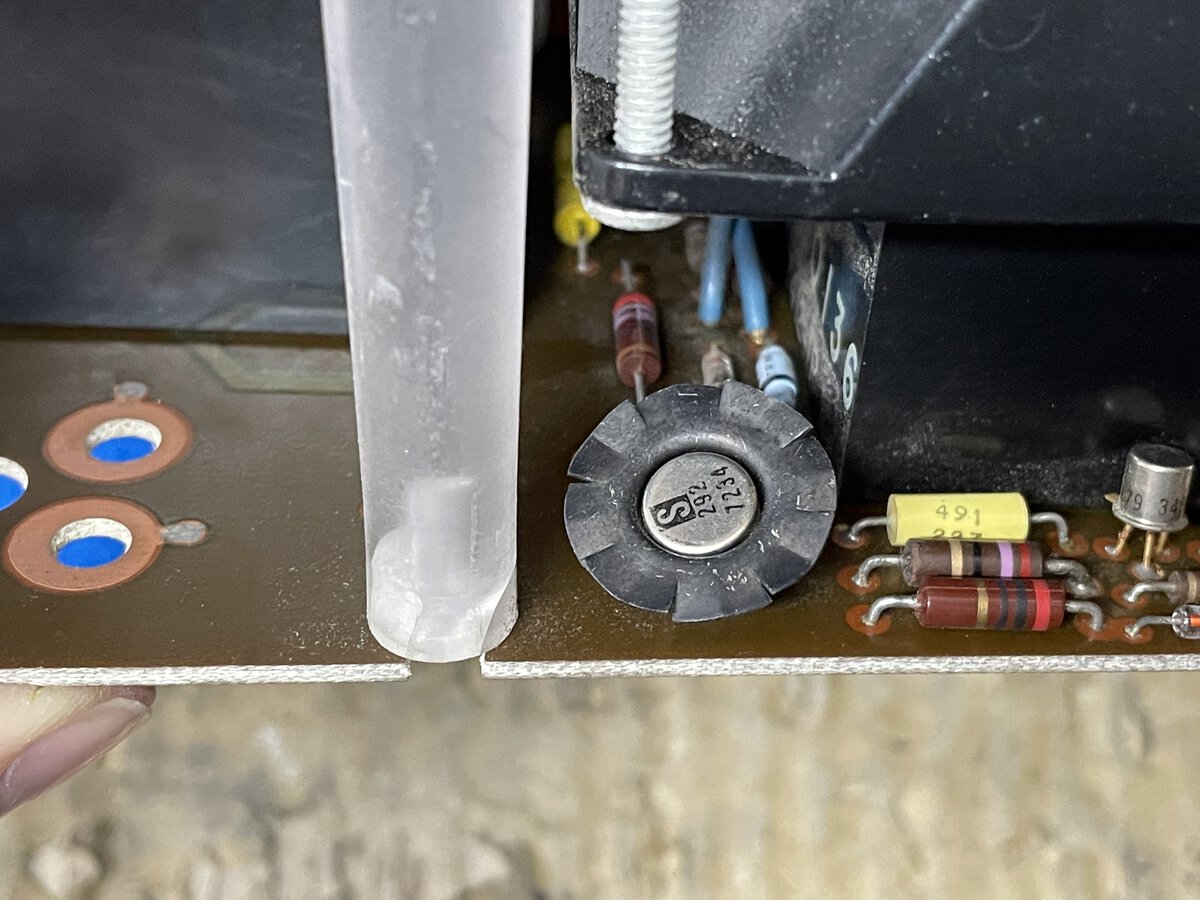
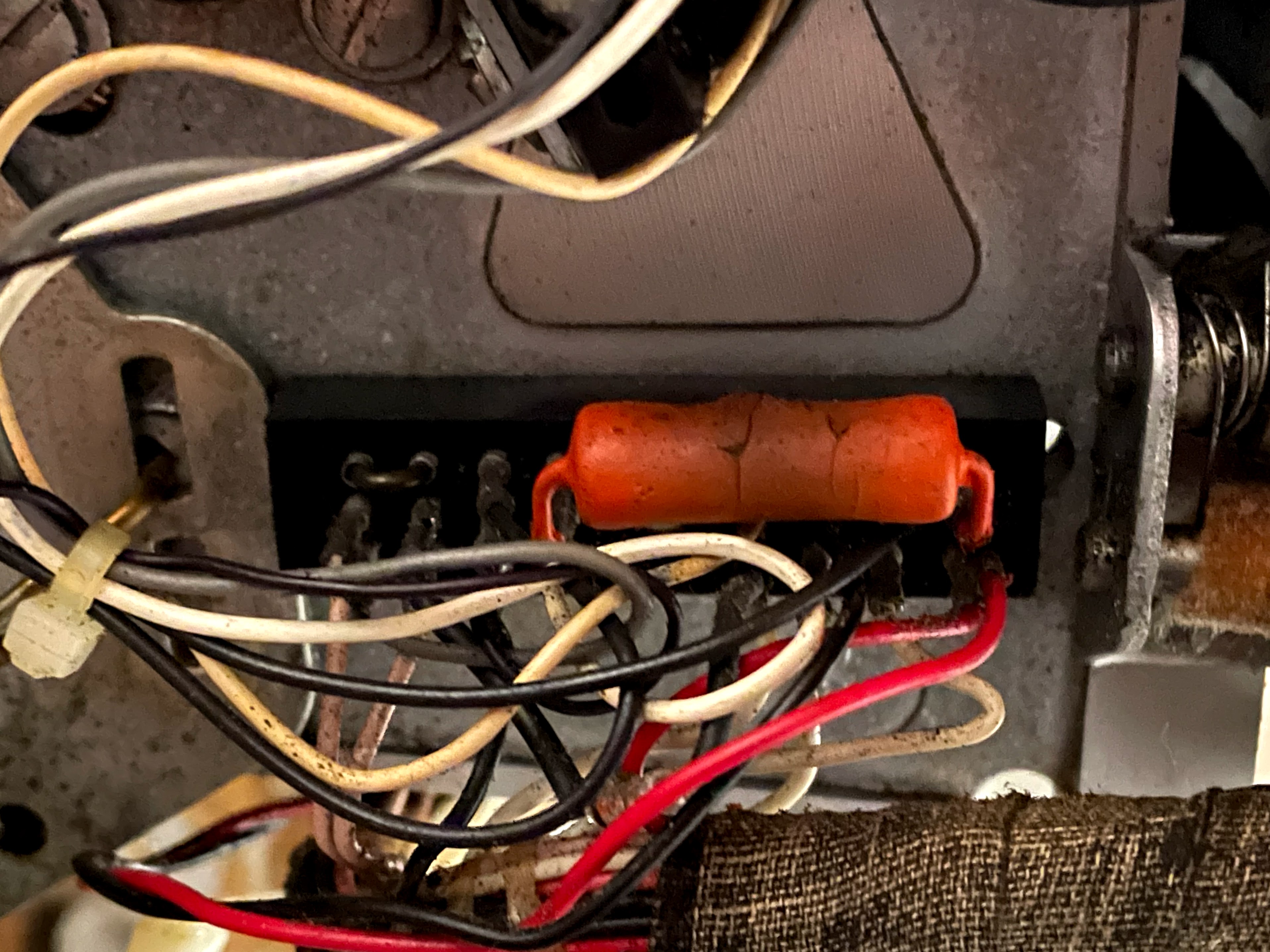
I thought at some point that this big orange resistor was dead, but apparently not. I suspect that it should eventually be replaced as it looks in bad shape. I established that it should probably be same as the tape loop resistor (which is marked 430 Ohms). I took it out, measured it, and it was 450 Ohms. Good guess! I suspect that it’s a 5W part.
Some stuff works!
Once this was fixed, I was able to show that quite a bit of the machine was working. It couldn’t print yet due to gummy parts, but I showed that it could record and replay! I shot a quick video showing my progress. You can tell that I was excited.
Even the bell worked at the end of the line. And that bell, mind you, is entirely controlled by electronics!
Conclusion so far
This first round of troubleshooting gives me hope that the machine can work again properly. But there is a lot more left to do.
More
- Blog post: The IBM Memory Typewriter
- Blog post: Restoring an IBM Memory Typewriter - Part 2
- Photo album: Pictures before restoration
- Photo album: All pictures of the restoration
Comments powered by Disqus.