
Background
See also:
- The TeleVideo TVI-912 terminal - Part 1, where I gather background information about the TeleVideo TVI-912 terminal, as well as my initial cleaning and testing of the terminal
- The TeleVideo TVI-912 terminal - Part 3, where I complete the restoration of the terminal
The bottom line of the previous post: although the terminal did power on and beeped, showing that there was good life in the main control board, and the CRT also showed some signs of life, the terminal didn’t display anything.
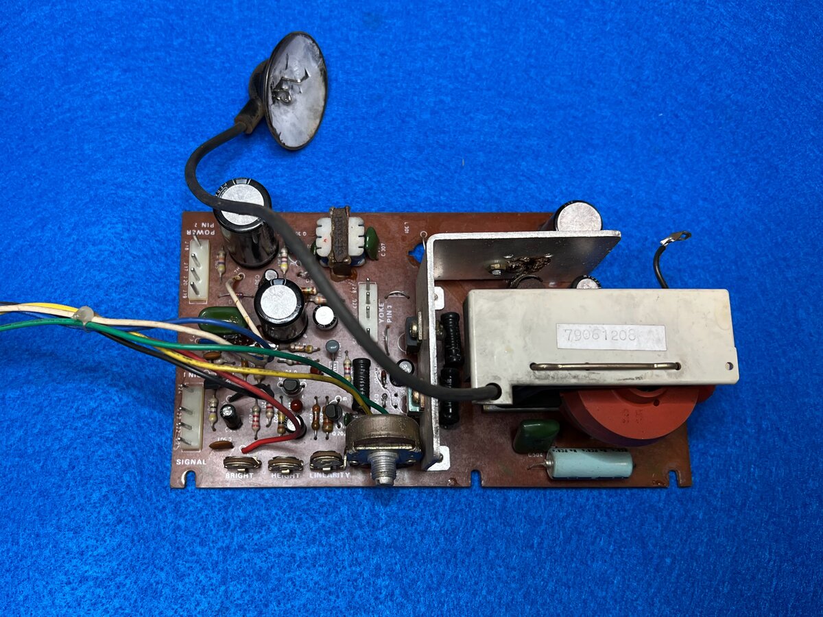
Video control board
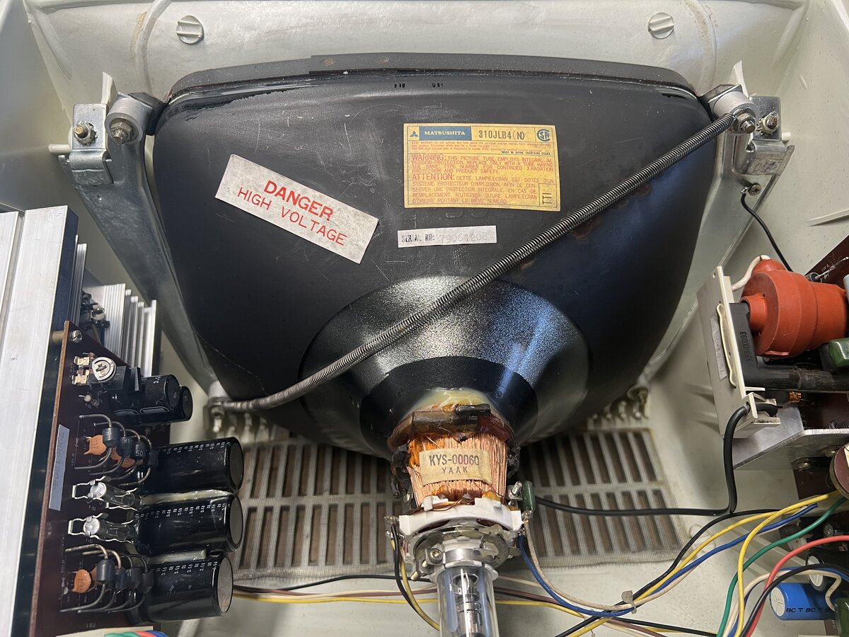
I was advised to look at the video control board. It is located in the top case, on the right. To remove it, remove the connectors, as well as (carefully) the small board with a socket that connects to the CRT tube. Finally, I also removed the wire going to the CRT’s anode, protected by a rubber cup.
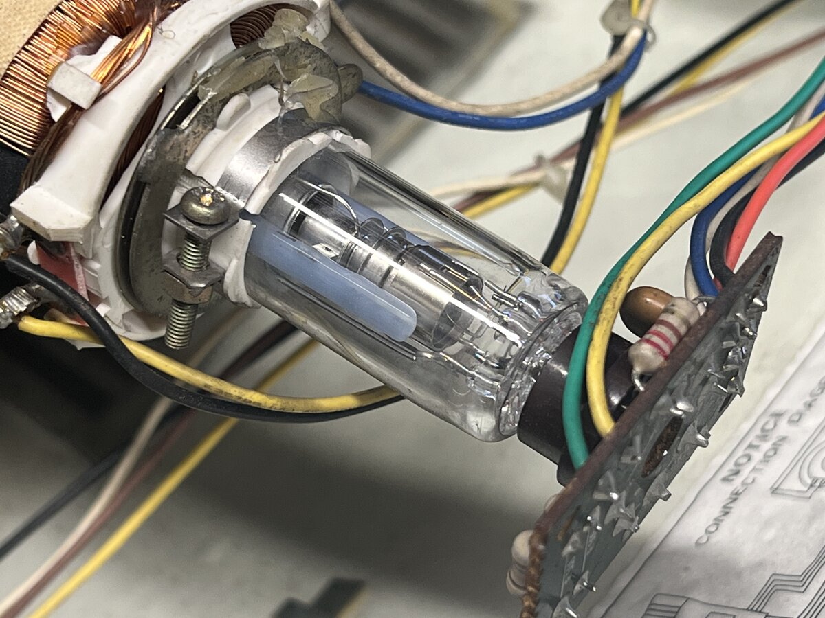
I followed the common advice of discharging the CRT tube by shorting the anode to ground with a screwdriver connected with a wire to the tube’s frame. My CRT was probably already discharged, as I hadn’t turned it on in a while. In any case I didn’t hear any pop.
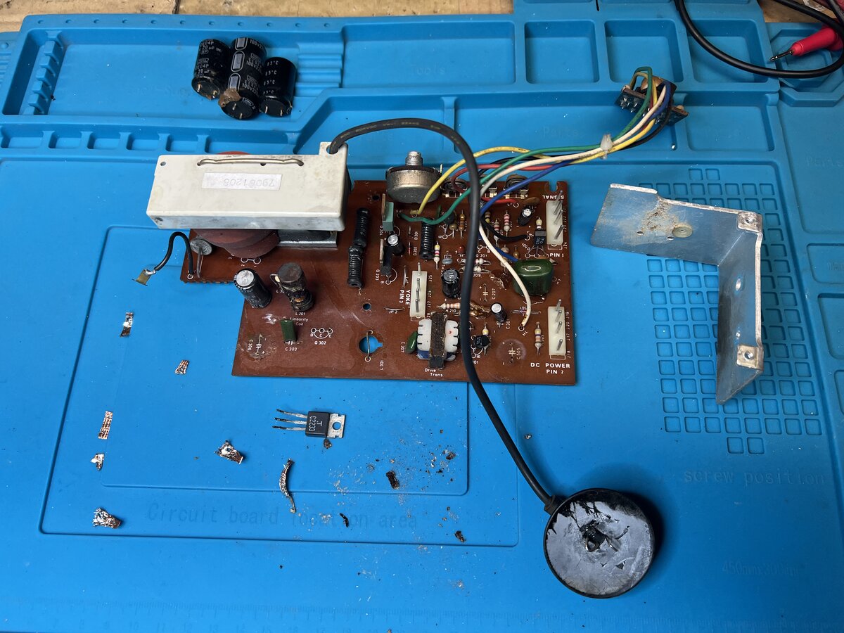
The usual culprits could be the electrolytic capacitors. They didn’t look great here, but I was told that mostly what this is glue, not a leak. The capacitors on the power supply board clearly are held with some kind of glue, although the color is different on this board.
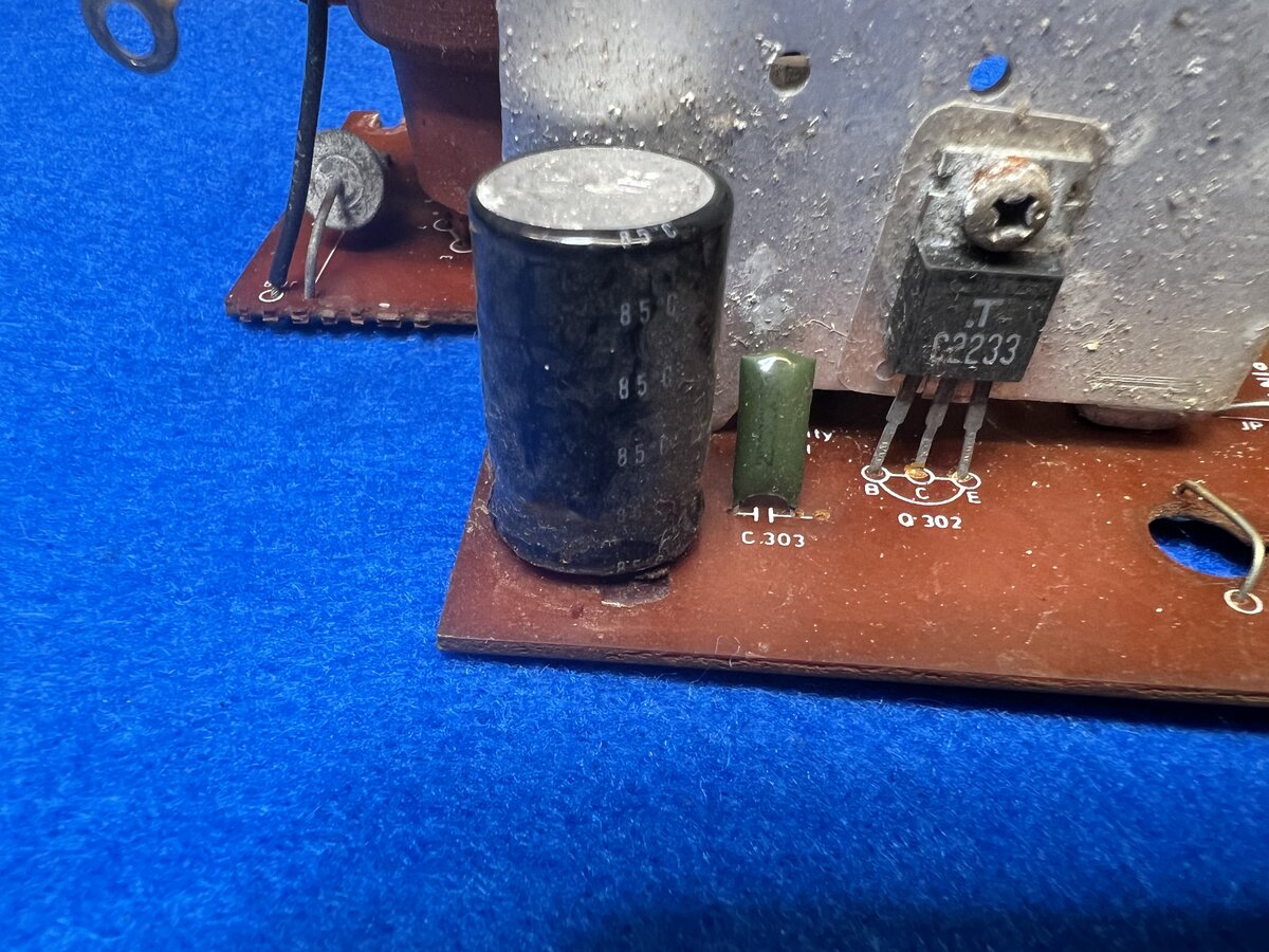
The Q302 transistor didn’t look that great either. Now, unsurprisingly, the datasheet for this C2233 transistor states “designed for use in TV horizontal deflection output applications”. Good! This part is no longer made, but there are some NOS transistors on eBay, in case a replacement is needed.
I decided to remove the heat sink on which 3 transistors are screwed so I could clean around.
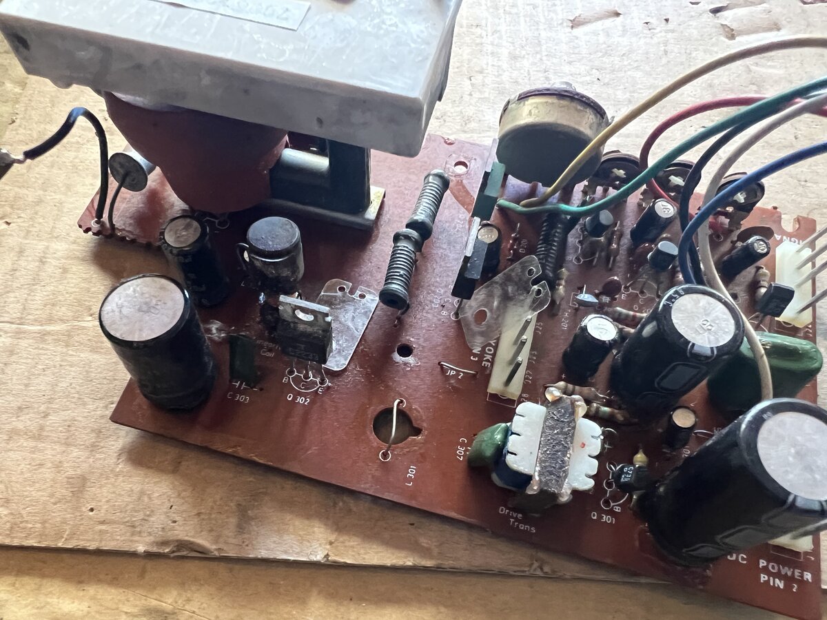
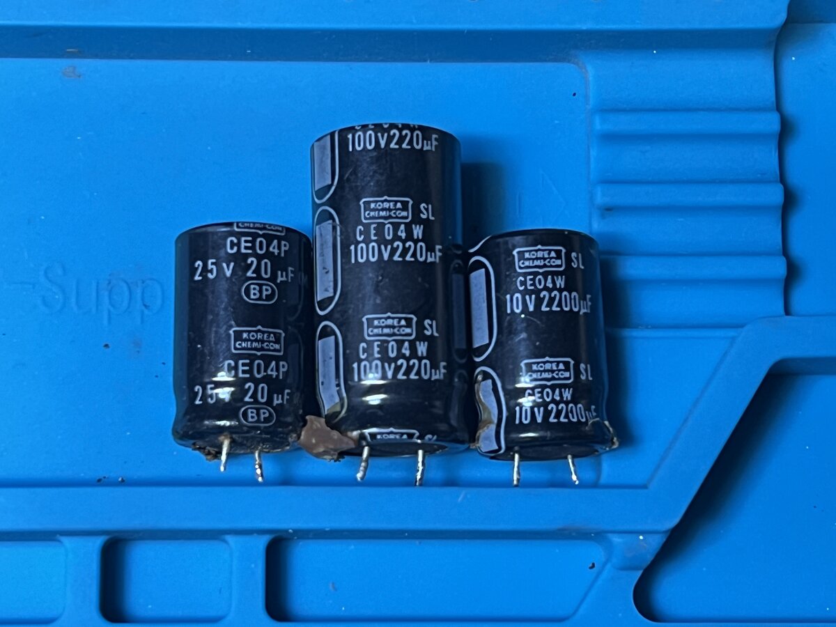
I then removed the larger capacitors. Interestingly, one of the larger capacitors is a bi-polar electrolytic. The other two are polarized, as is the case of most electrolytic capacitors. I ordered replacements for all three.
I desoldered the C2233. I don’t have a transistor tester, but I quickly tested it with my multimeter’s diode tester. I am getting 0.5 V between base and emitter as well as base and collector in one direction, while I am getting nothing the other way. So the transistor was not entirely bust (in fact it was still good).
First run of the self test
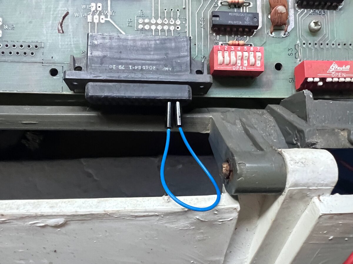
While waiting for the replacement caps, I checked the manual, which describes the self test feature:
- connect the DB-25 connector’s pins 2 and 3
- short a jumper next to the keyboard connector
The terminal will run the self test, and then beep when done. The screen should show a pattern of characters. I had the video board disconnected when doing this, so couldn’t see the result, but the terminal beeped after a few seconds which was encouraging!
Since I had the terminal in loopback mode, I tried CTRL-G again, and this time it worked!
Bottom case and derusting
The bottom case was full of dust and dirt. I removed the keyboard, control board to clean it in depth.
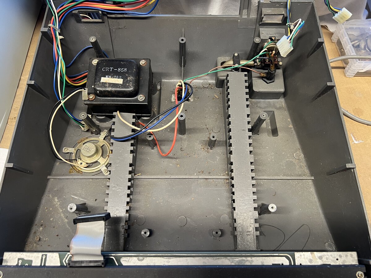
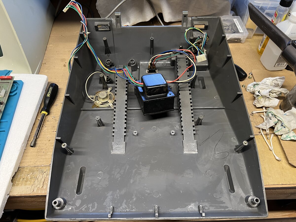
I also removed the transformer to clean underneath it.
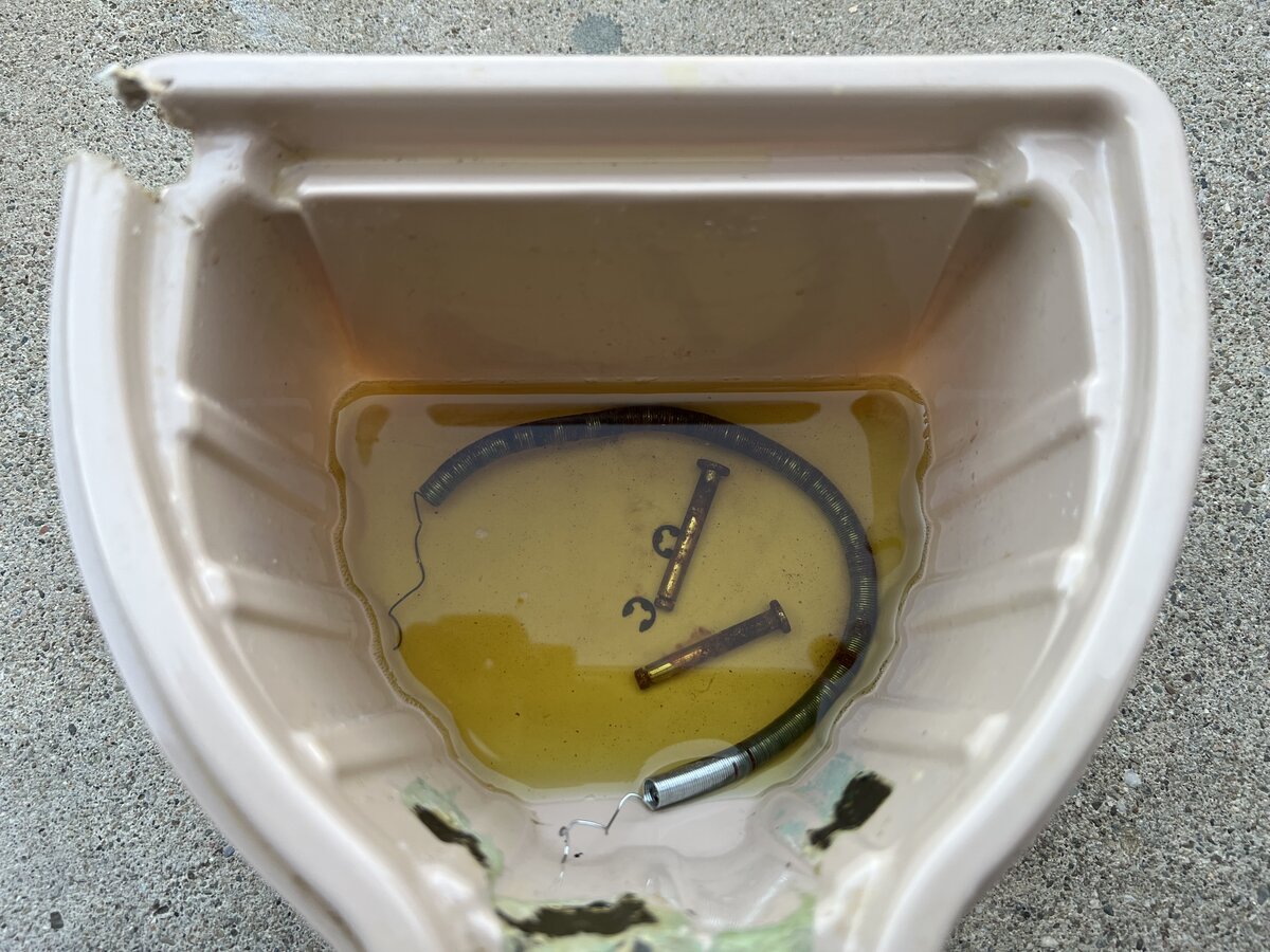
There was rust on the washers of the transformer, and I Evapo-Rusted that, as well as the screws, and the 110/220 screw on the bottom, as well as the metal bolts for the hinges.
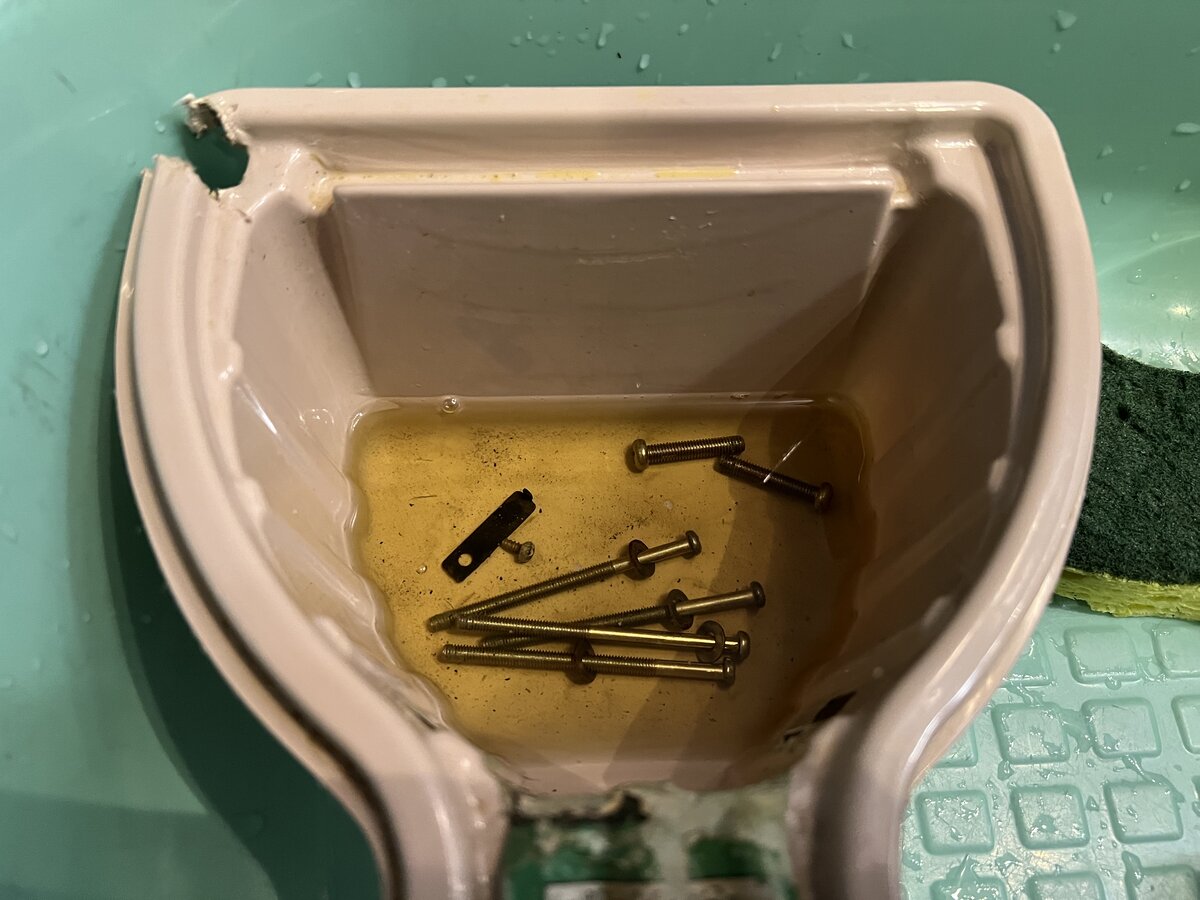
The CRT spring also got the Evapo-Rust treatment.
The hardware looks better after derusting.
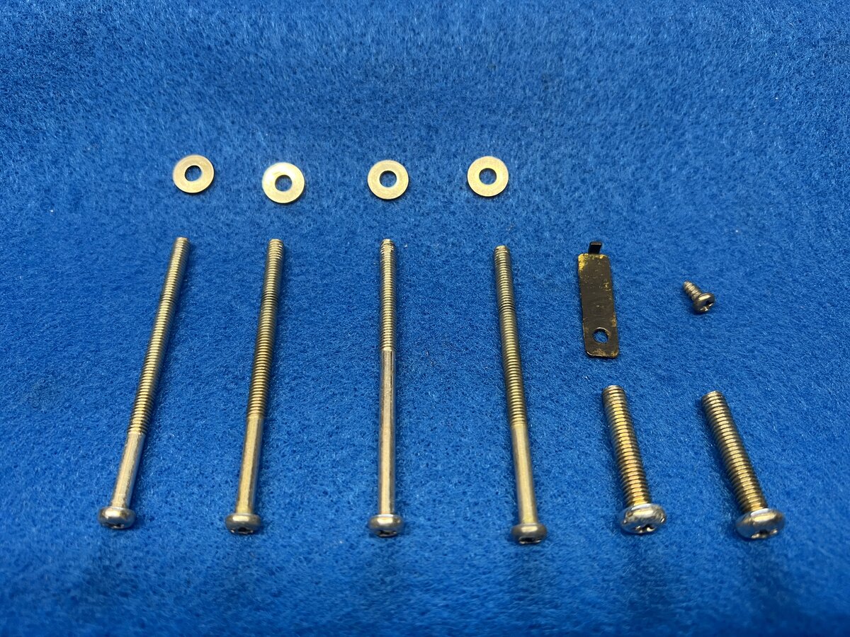
And so does the spring.
I also cleaned the glass of the CRT tube.
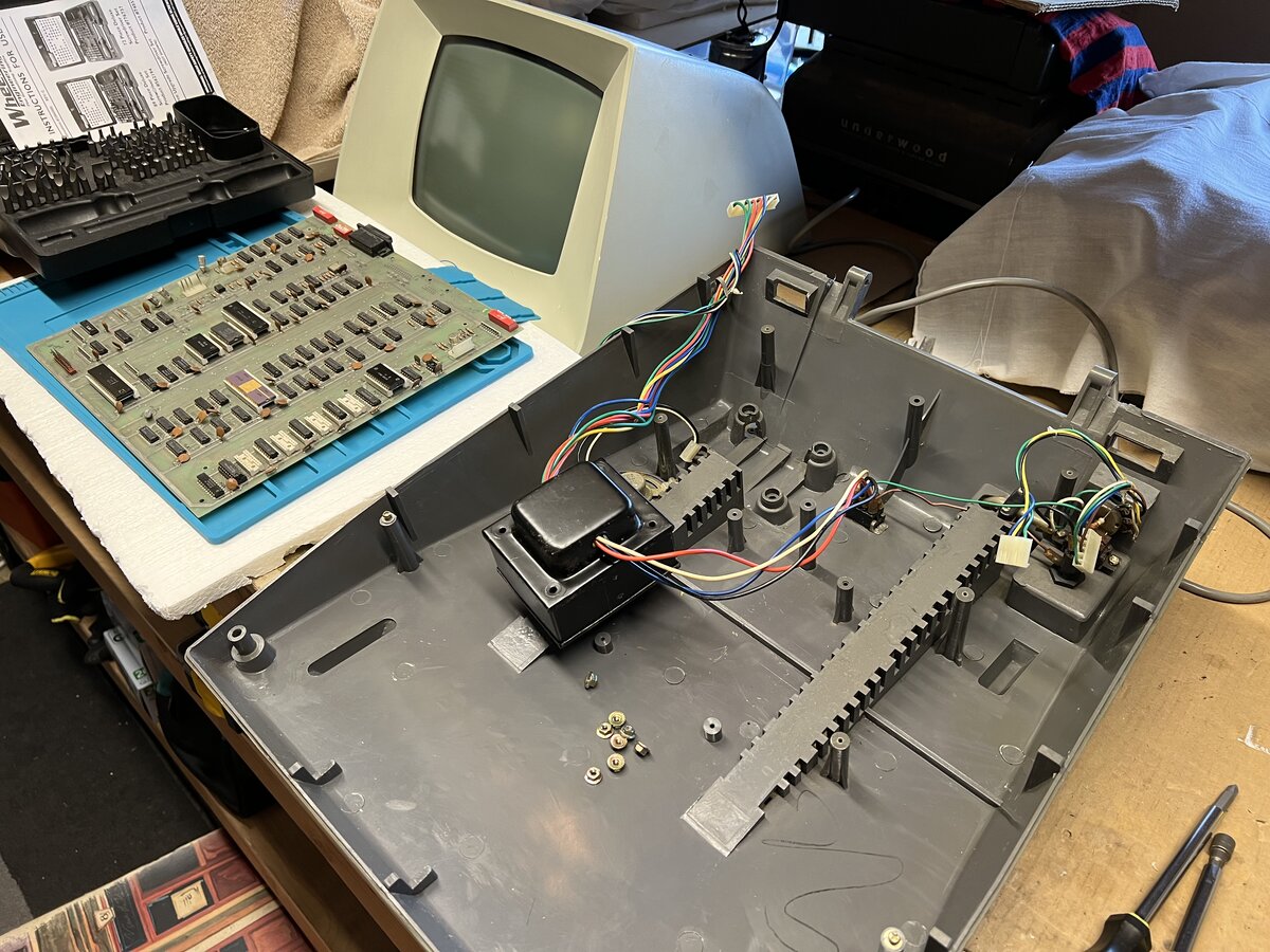
This is a view of the terminal during cleaning.
Removing the main control board allowed me to see the bottom of it. It has a solder mask, unlike the top!
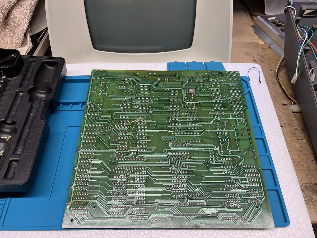
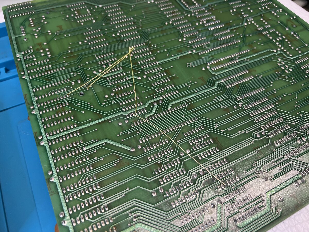
It’s a beautiful board, without any trace of damage, by virtue of being on the bottom and well protected from dust. Notice the four yellow bodge wires.
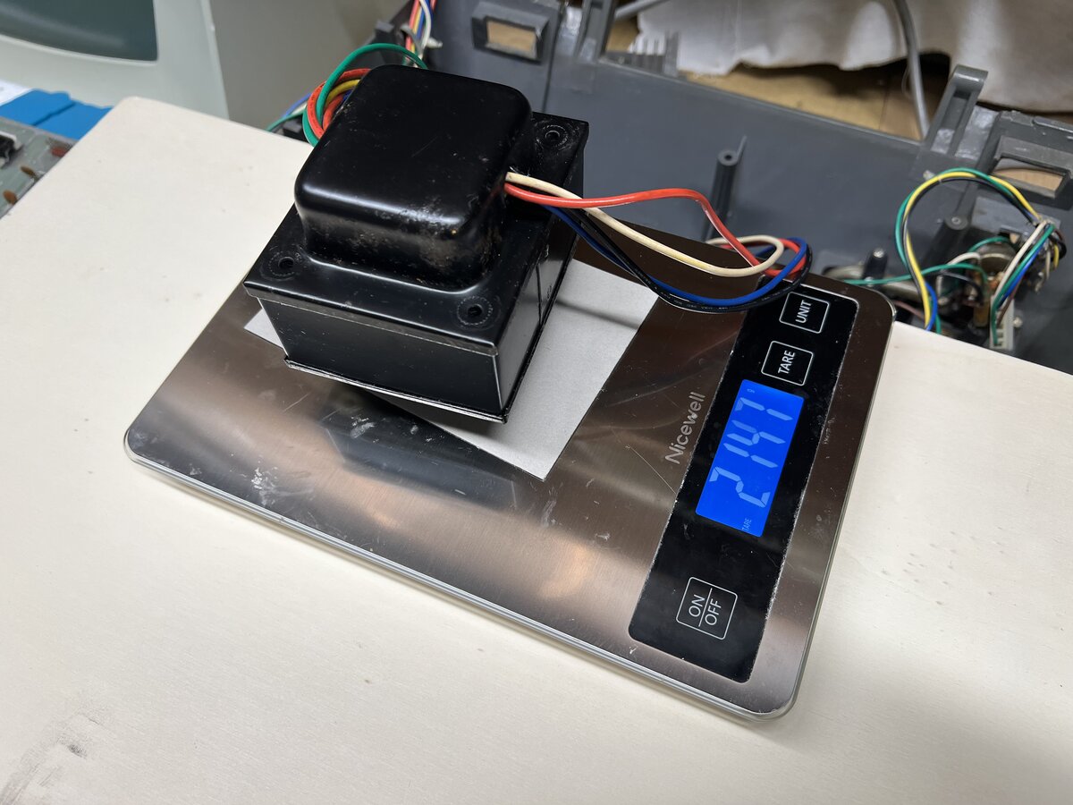
The transformer is quite heavy at 2.147 kg (4.73 lbs)!
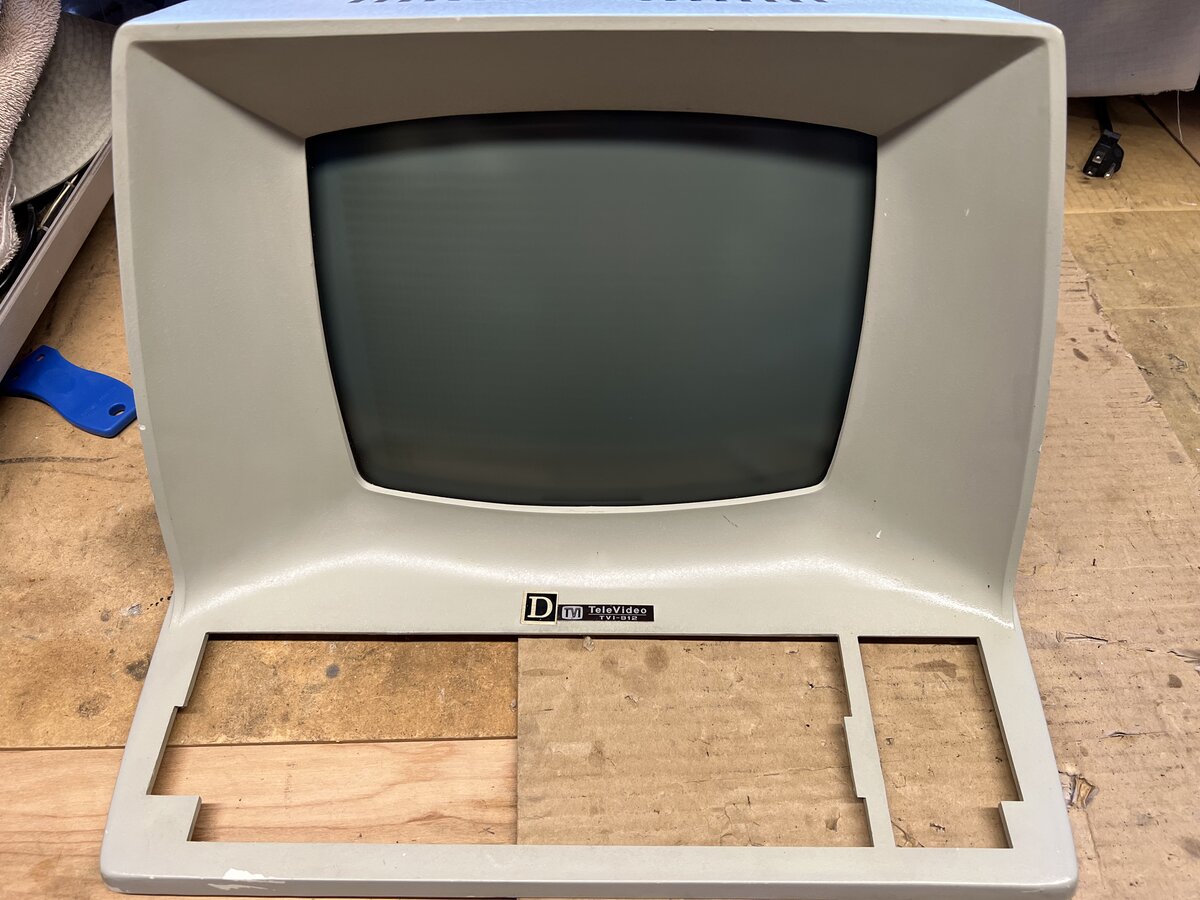
Cleaning the top case
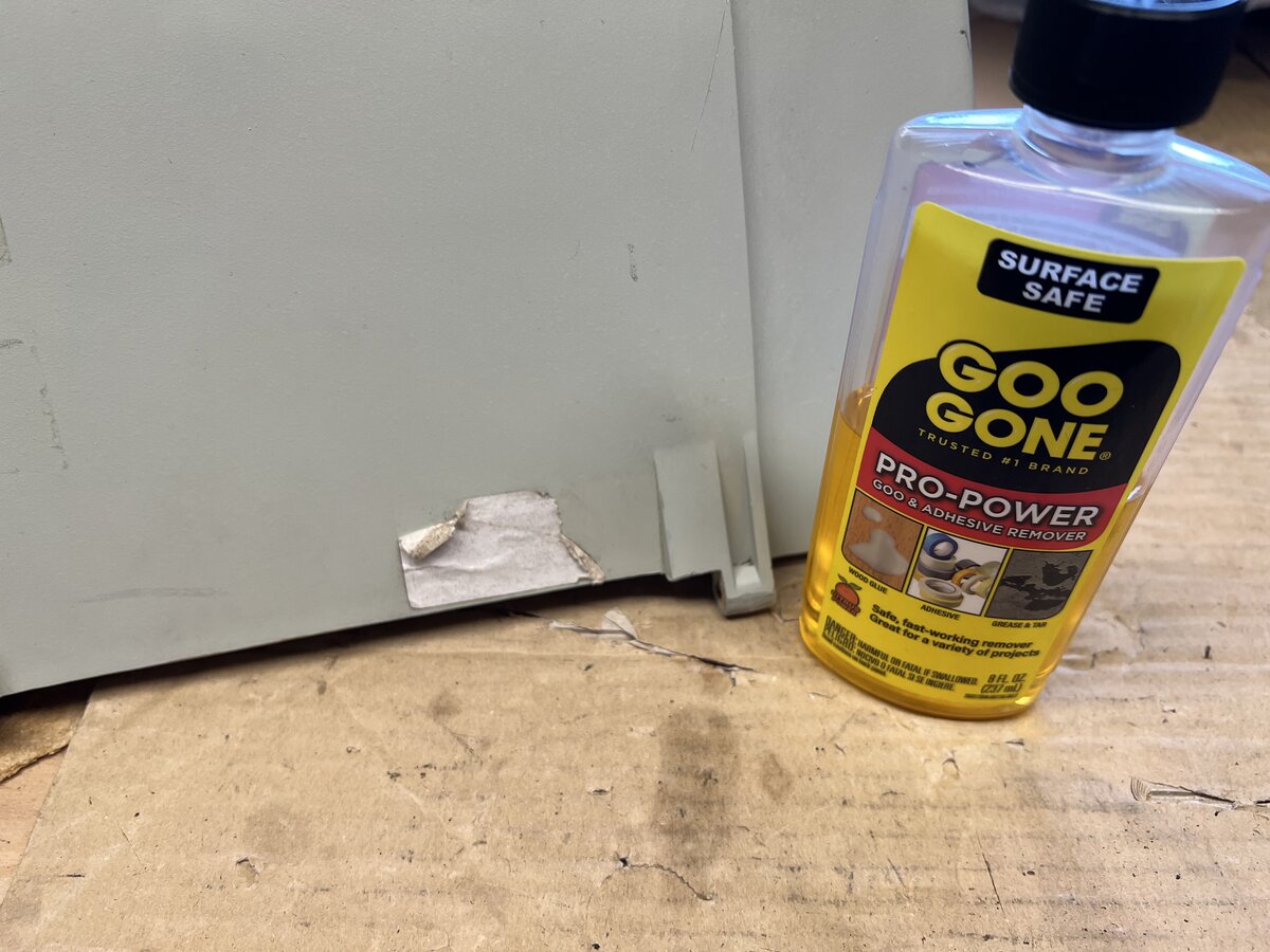
The top case got light Simple Green treatment. It is made of some kind of plastic, like the bottom case, but it is painted. The sticker in the back went away easily with Goo Gone.
There were ink stains, and other stains, on the paint, and most of it went away with patient application of Hoppe’s #9.
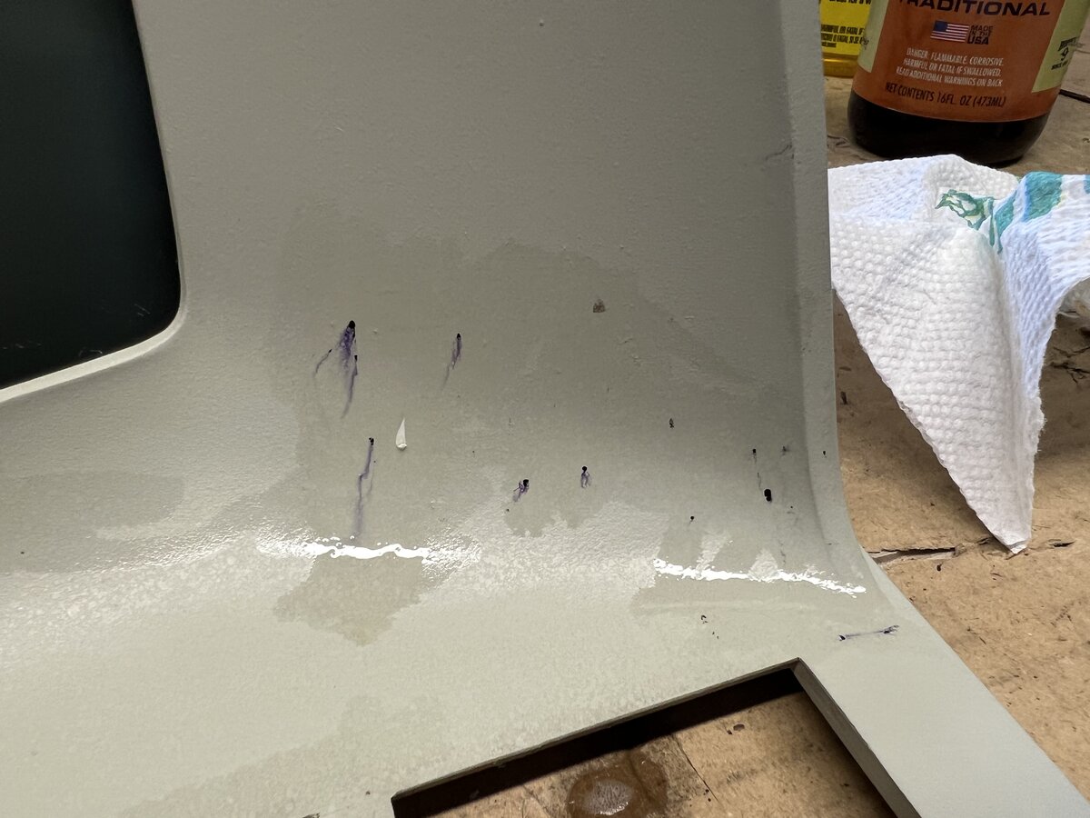
There are still some stains, and for now they will remain, but it’s better than before.
Trying the new capacitors
I soldered the 3 new capacitors on the video board. I was surprised at how small the new bi-polar electrolytic capacitor was! In any case, after putting things back together I turned on the terminal, with some angst. Curiously the first time the terminal beeped longer! I think I turned it off and then on, and then it showed something on the screen! The new capacitors had done the trick!
However, that was not the end of the story. While, something showed on screen, there was some corruption. The cursor moved, characters typed too, but incorrectly in some places. I found out that only one area of the screen was working correctly. Could it be that only one out of the four RAM chips worked?
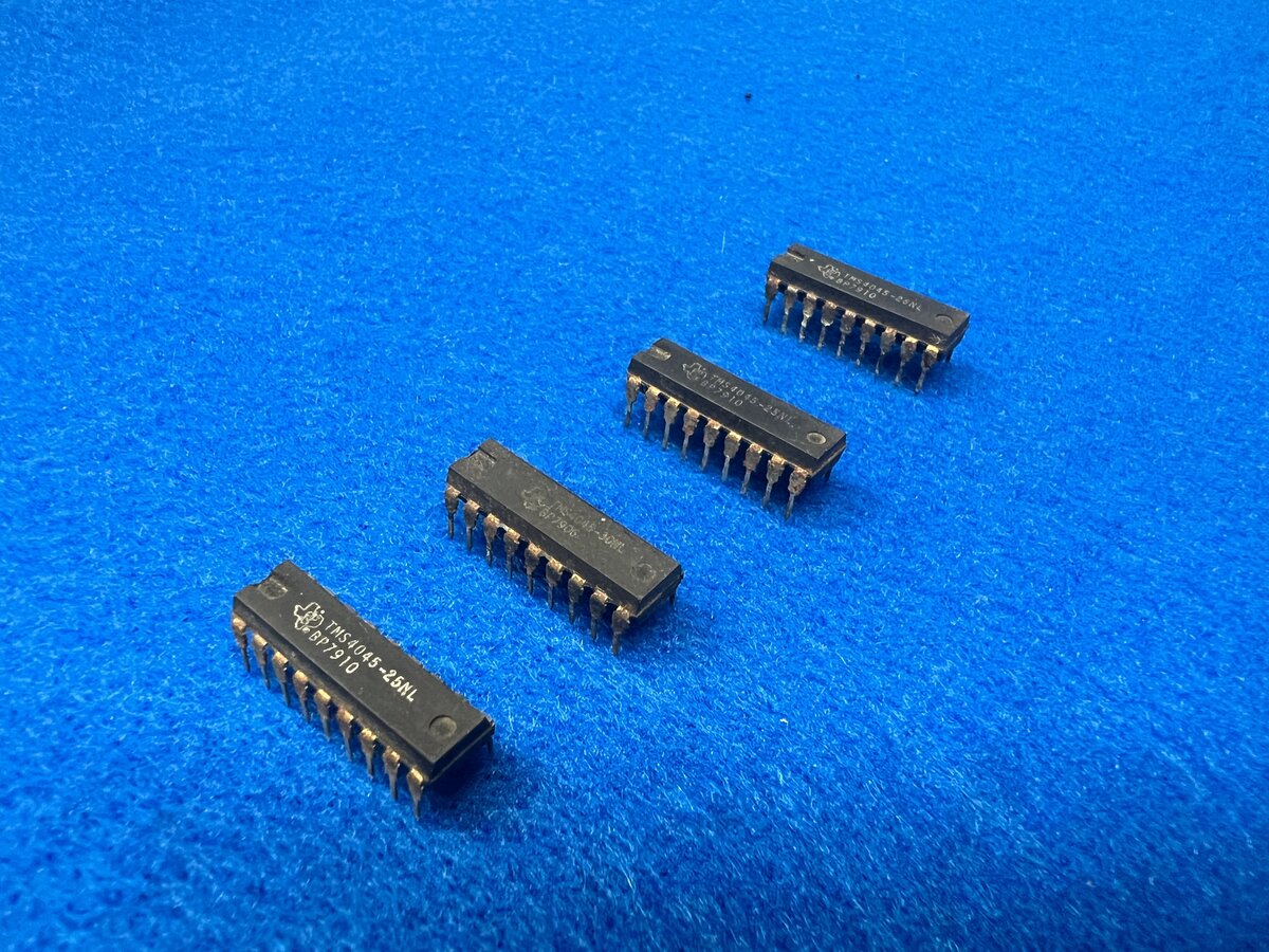
I was advised in a forum that those RAM chips tended to fail, and that the sockets could also be bad. I took out the 4 RAM chips.
I put them back, but the problem persisted.
Building a RAM tester
I figured that I should test the RAM chips, but how? The principle is simple: iterate over the address range, write all 16 possible data values, read them back, and compare the values. You can, of course, do more sophisticated tests, but any write/read test will be good as a start. The chips are simple:
- 10 address lines
- 4 data lines
- chip select
- write enable
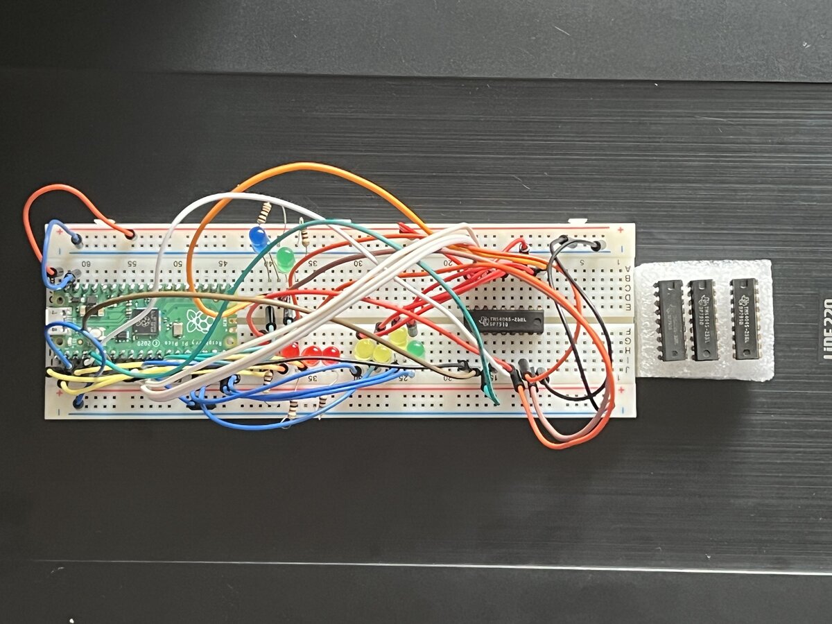
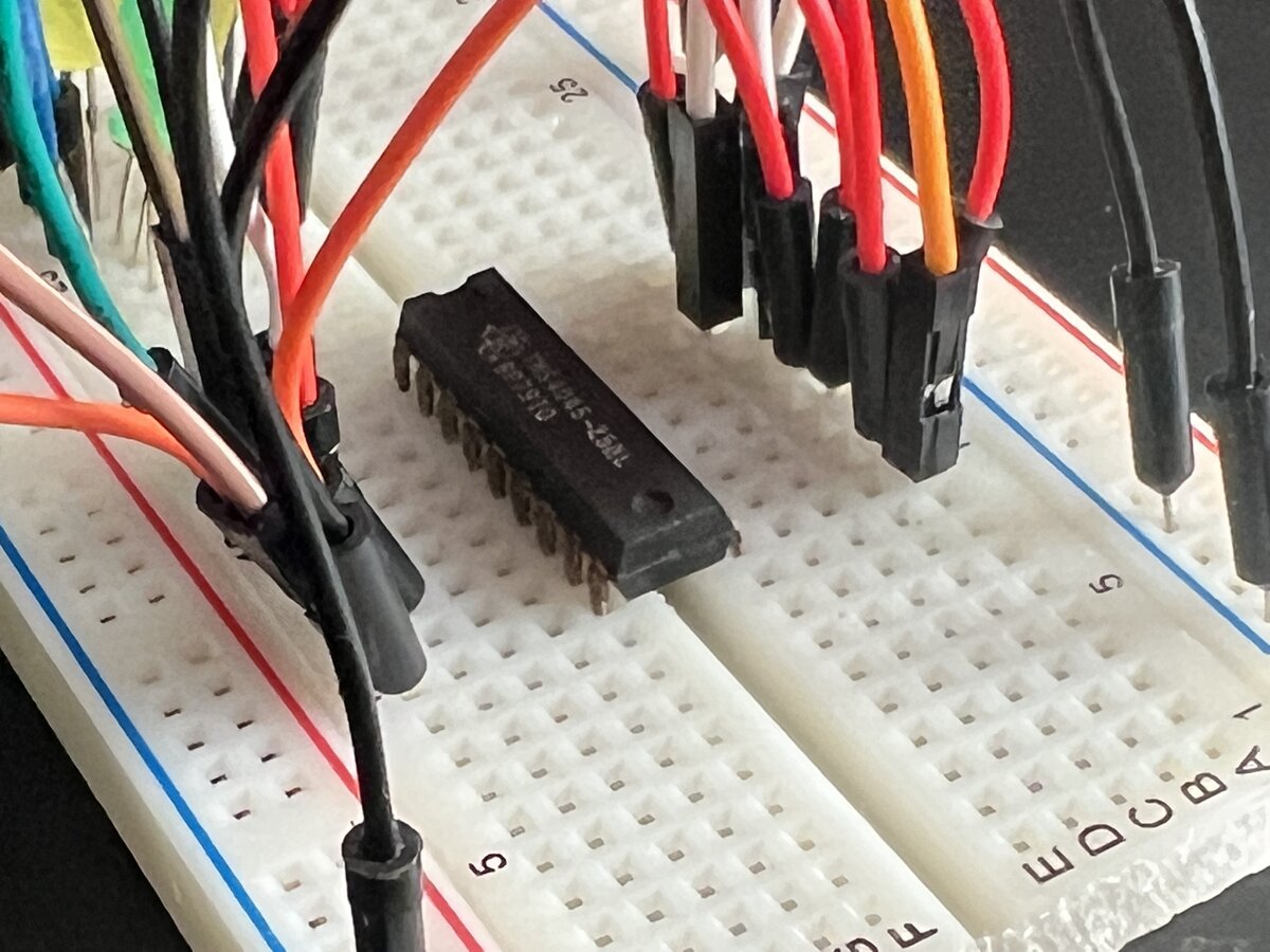
I figured I would use a Raspberry Pi Pico (RP2040-based) as I have one at hand. Writing a simple C program to do that is pretty simple.
I calculated that the software simulation will be slower than the minimum timings of the RAM chips, but again, it’s ok for a basic test.
I thought about a potential issue: the RAM chips are 5V chips, while the RP2040 is a 3.3V chip. However, it turns out that the RP2040 has some 5V tolerance, and so level shifting was probably not going to be needed. I took the risk.
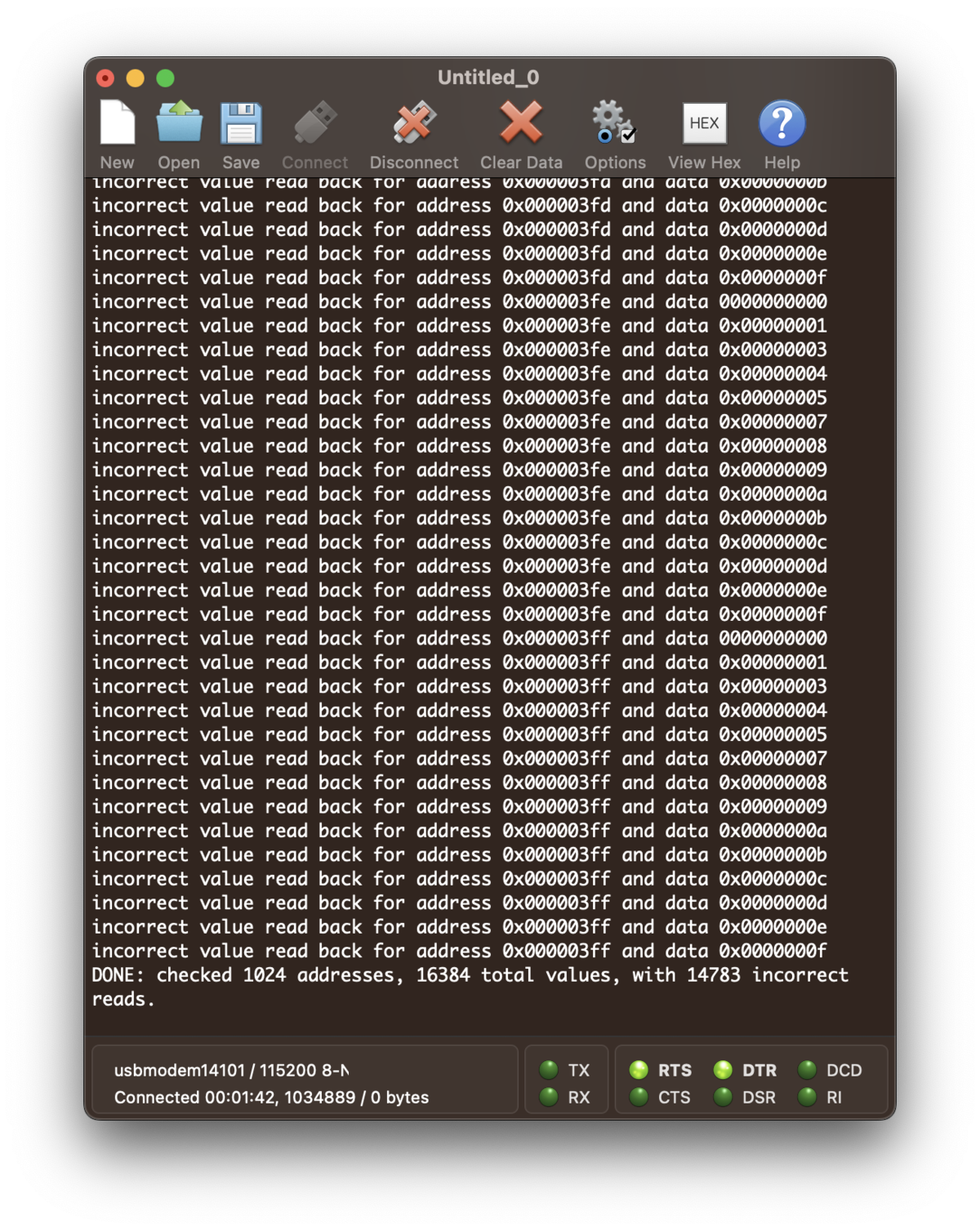
I wrote the program, then ran it very slowly just with LEDs and then disconnected the data LEDs and put one of the RAM chips. My test reported many failures! Then I put the other chips, and they all passed. I concluded that I had one failing chip, and 3 good ones (I had guessed the opposite). But I could not rule out other issues, like the sockets or something else.
I am quite happy that I was able to write a basic tester so easily (and I showed it off to friends too). I might write a ROM reader too later.
Replacing the memory chip
I ordered replacement chips on eBay. I picked the 9114 chips (AM9114DCP to be exact), supposed to be 100% compatible, as chips with the original markings were significantly more expensive. In this case, the chips came in a set of 4, which would give me some spares just in case.
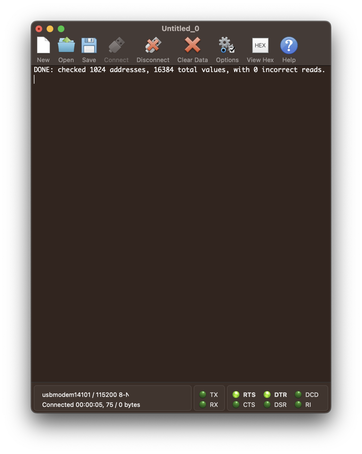
Once I got the memory chips, I tested one in my tester, and it passed. So I used it along with the other 3 original chips. The terminal worked!
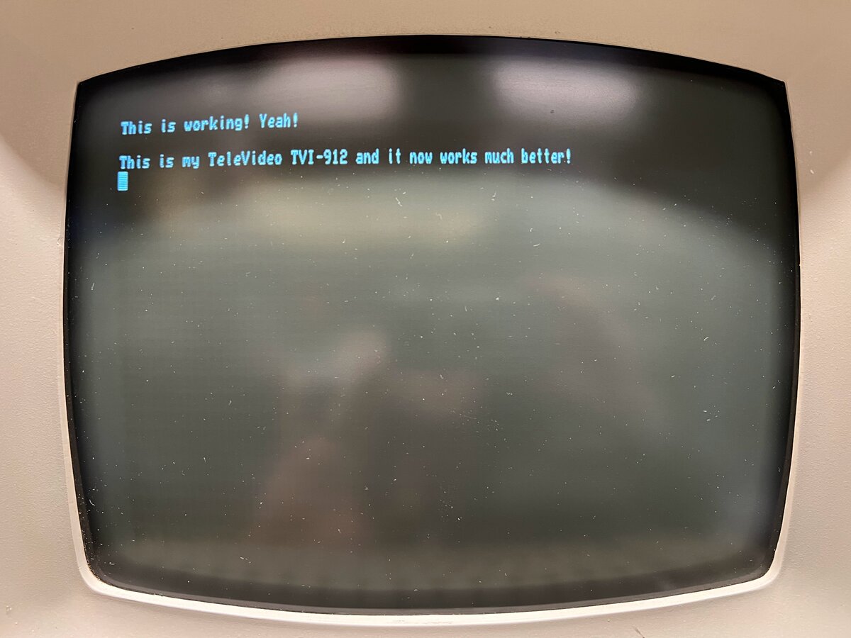
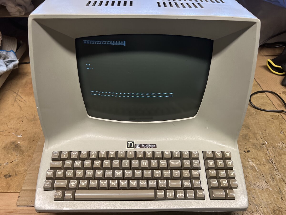
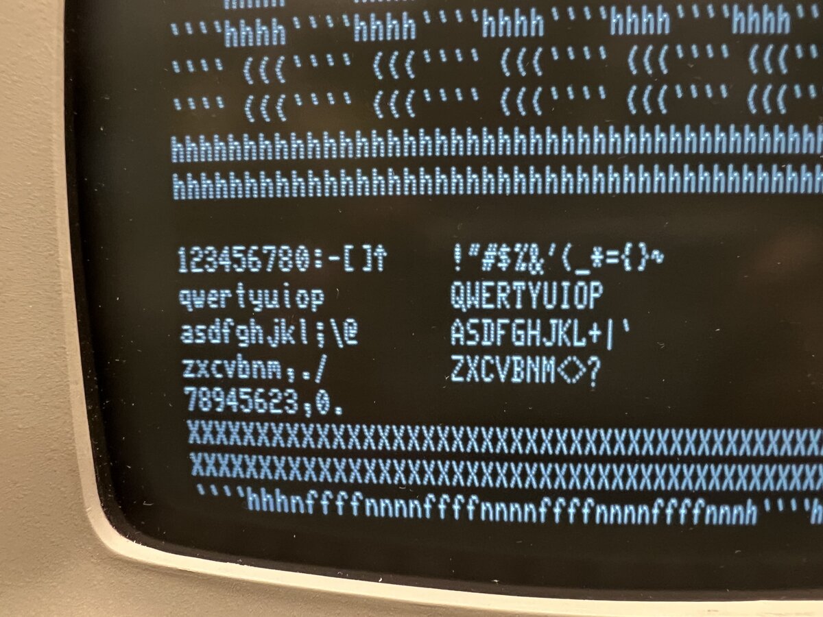
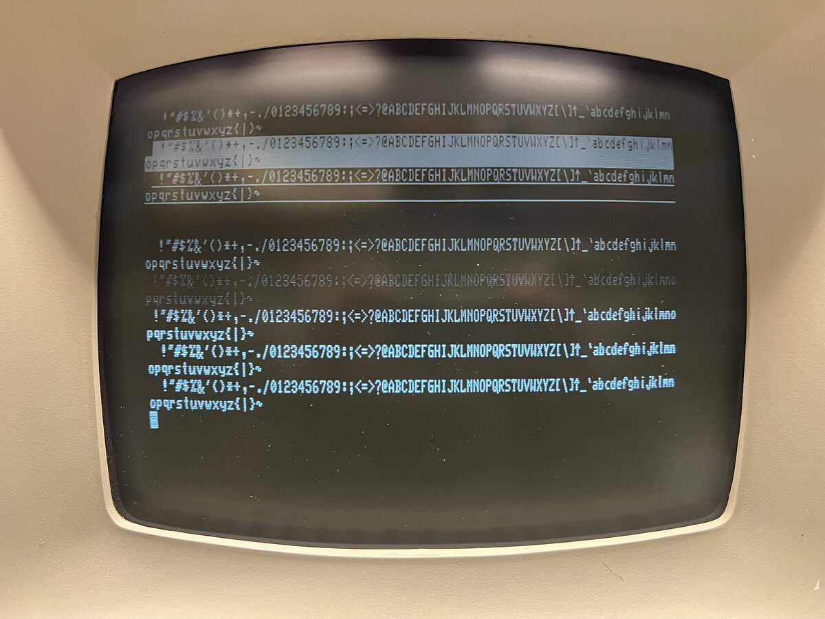
I ran the self test again and this time I could see the full test pattern on the screen!
Talking to the Altair-Duino
Now that the terminal worked, I had to connect it to something. I wanted to try connecting it to my Altair-Duino first. If you don’t have an actual original Altair or a modern recreation, this is the next best thing: it’s a wonderfully-made kit.
But first, RS-232 fun! The terminal has an old-style female DB-25 RS-232 connector. My Altair-Duino has a female DE-9 connector. I had to order a DB-25 to DE-9 adapter and a cable.
The connection didn’t work at first. I went through the Altair-Duino configuration for the serial port, many times, but to no avail. I started having doubts that my serial port on the Altair-Duino was even selected or properly connected.
I had also ordered a USB-to-serial adapter. In fact, I first ordered a Sabrent-branded one, but it turns out that it’s hell to make it work on the Mac, so I returned it and instead got an adapter with another chip which has built-in drivers on the Mac.
I proceeded to connect my Mac, via CoolTerm, to the Altair-Duino, and it worked! So I now knew that my Altair-Duino serial port was working properly. 1
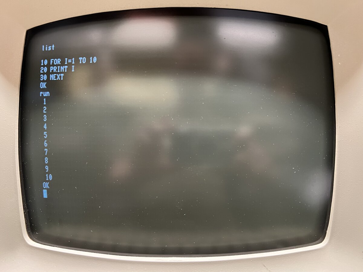
Confident about the Altair-Duino side, I managed to connect the TVI-912 to the Altair-Duino: one issue was that it worked at 4800 bauds, while it didn’t work at 9600 bauds (the highest speed on this terminal). It would be good to figure out why at some point.
Loading BASIC on the Altair, I ran a test program.
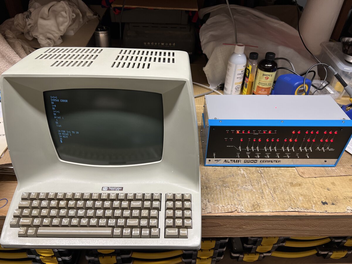
Here is the test setup on the bench:
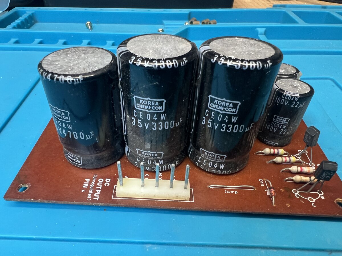
Power supply
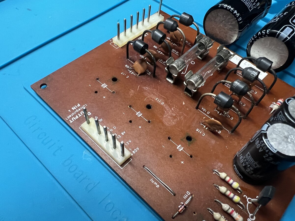
Even though the terminal was now working, there were still a few steps. First, the power supply board. I started by taking it out again and cleaning it.
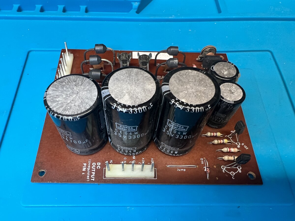
Then I wanted to test the three large capacitors on that board.
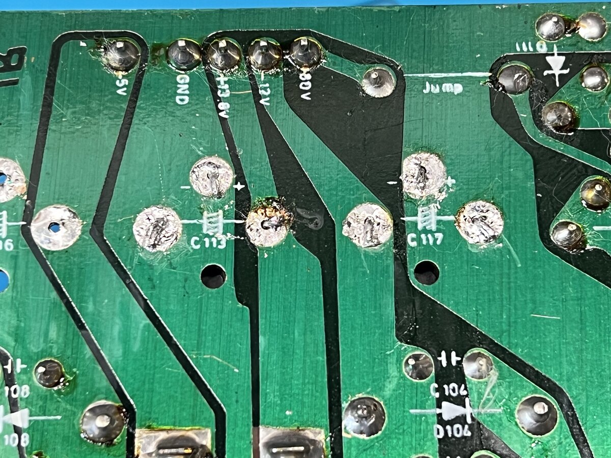
I decided to desolder them.
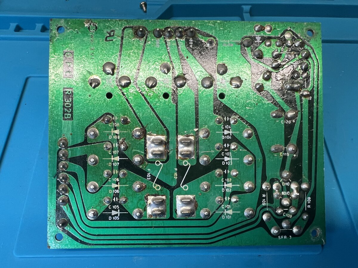
It wasn’t easy because the leads of the capacitors were bent down on the board, presumably for mechanical stability.
But it eventually worked.
I started the process of reforming them. For the 16V capacitor, this was easy as I have my HP E3615A 20V power supply.
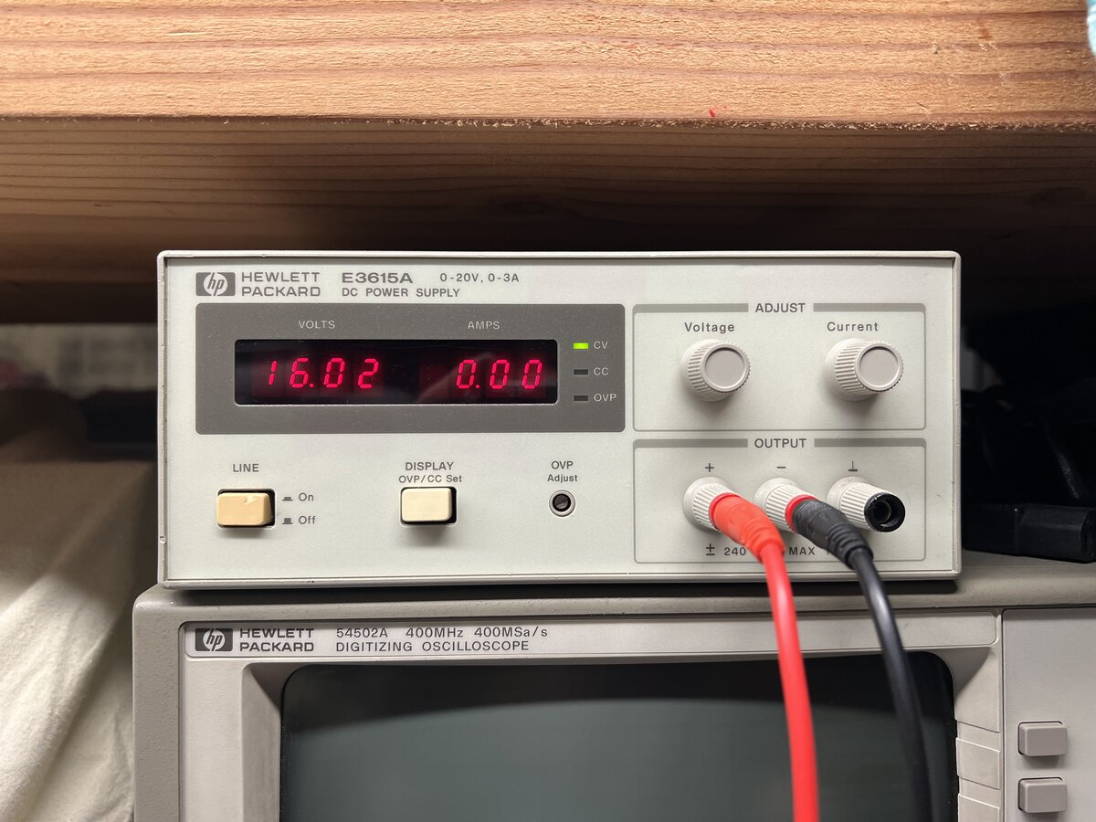
I followed the steps, starting at a low voltage and allowing at most about 2.5 mA, all the way to 16V in 1-2V steps. I definitely noticed that it took time for the current to come down to zero at each step, but after the process, much less time - which is exactly the idea of reforming electrolytic caps.
I followed the process as well for the 35V caps, but only up to the maximum voltage I could produce, that is, 20V.
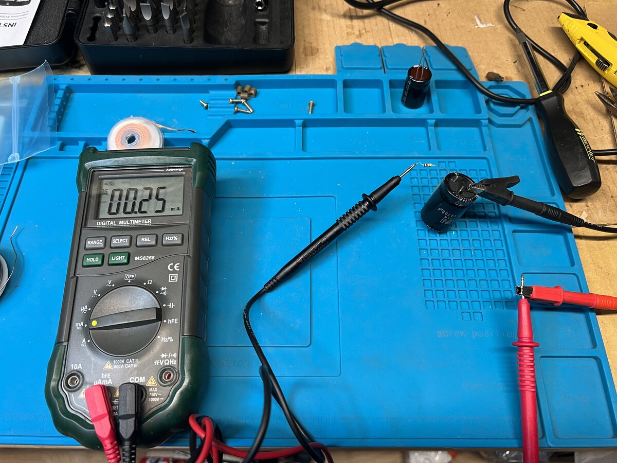
I didn’t have a working capacitance meter when I started this, so I didn’t measure the caps before. But I did after, and it turns out that the two large caps measure great, in fact they hold a little more than the 3300 μF they boast. The 4700 μF cap, on the other hand, was significantly below. It worked well enough, but I decided to replace that one. The new capacitor is a little smaller, but it fits in those holes. I’d have had trouble replacing the other two due to the layout of the holes, so it turned out well.
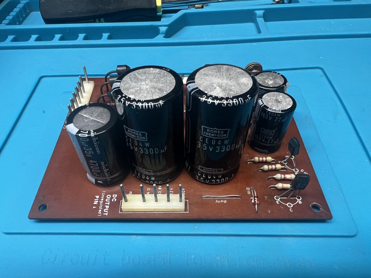
I then replaced the power supply board in the machine.
Next steps
There are a few more steps to go through to consider the project complete, including:
- consider replacing some IC sockets
- cleaning the keyboard
You can read about this in The TeleVideo TVI-912 terminal - Part 3.
See also
- The TeleVideo TVI-912 terminal - Part 1
- The TeleVideo TVI-912 terminal - Part 3
- Photo album: Televideo TVI-912 terminal (1979) - Part 1
- Photo album: Televideo TVI-912 terminal (1979) - Part 2
- Photo album: TeleVideo TVI-912 (1979) - Restored
I had previously only connected my Altair-Duino directly to a VGA monitor and USB keyboard. This is a neat feature of the kit, which has this little optional board which emulates a VT-100 terminal. ↩
Comments powered by Disqus.