
Background
See also:
- The TeleVideo TVI-912 terminal - Part 1, where I gather background information about the TeleVideo TVI-912 terminal, as well as my initial cleaning and testing of the terminal
- The TeleVideo TVI-912 terminal - Part 2, where I fix the video control board and memory and manage to ge the terminal working
RAM IC sockets
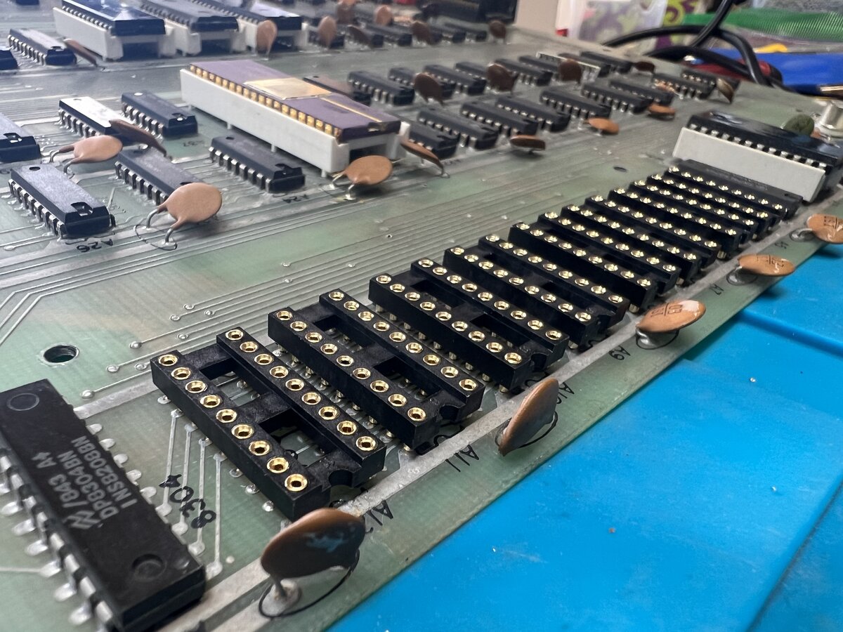
The next thing I wanted to do was to replace the memory chips’ sockets. For some reason, these chips show the most signs of corrosion. Now I could have left things as they were, but figured installing new sockets would be a neat upgrade. So I proceeded to do just that, opting for machined sockets.
I figured, while I was at it, that I would also replace the unused 4 extra sockets. Those are designed to hold a second screen page. This was an optional feature, and these sockets were unpopulated on my machine. But if I ever wanted to try the upgrade, new sockets would be good here.
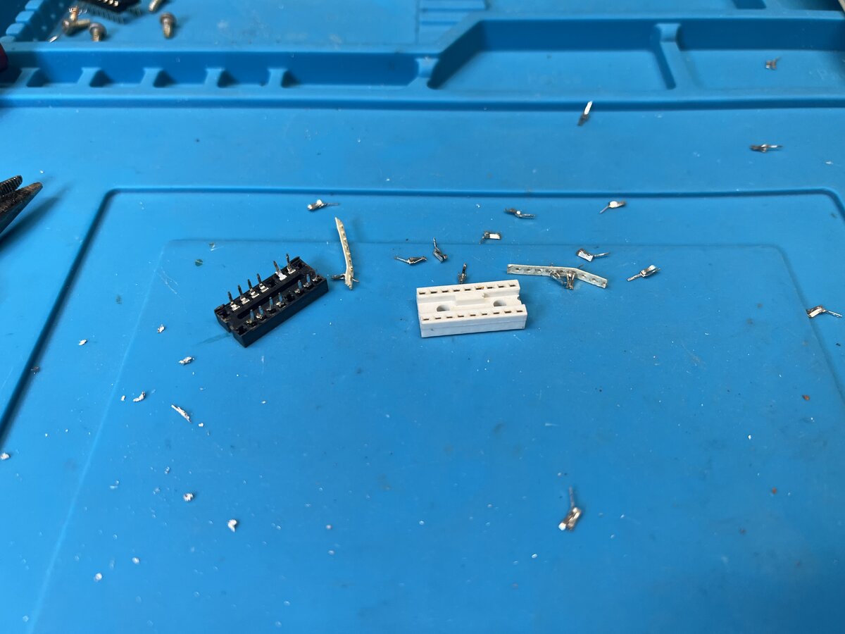
Desoldering was a little painful. The good part is that the sockets easily come apart in the process, and I had to just pull out the pins one by one.
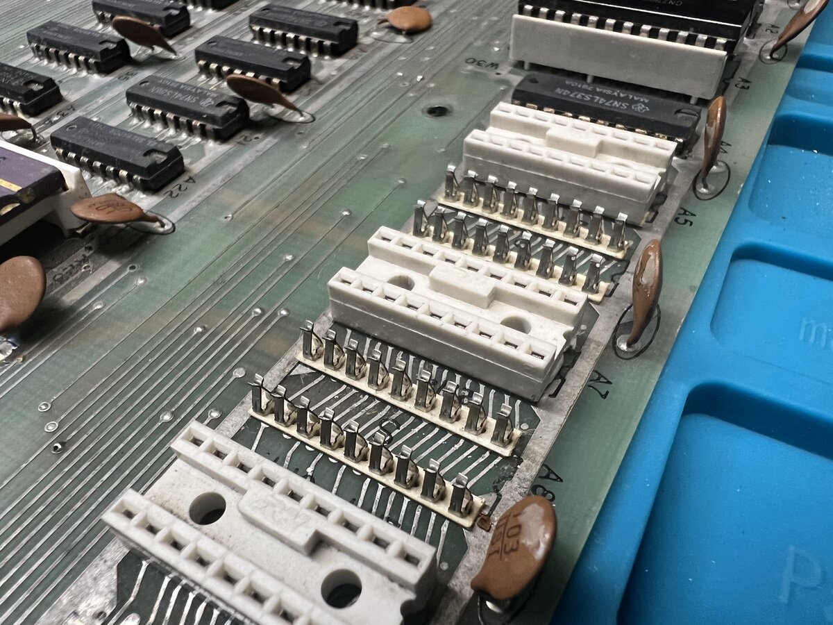
Only one of the sockets was black, while the other seven were white, and there were traces of flux under that specific socket on the bottom of the board. I suspect that this socket had already been replaced in the past.
After desoldering, I cleaned the board with distilled vinegar and then alcohol - the former to try to remove some of the corrosion on the top.
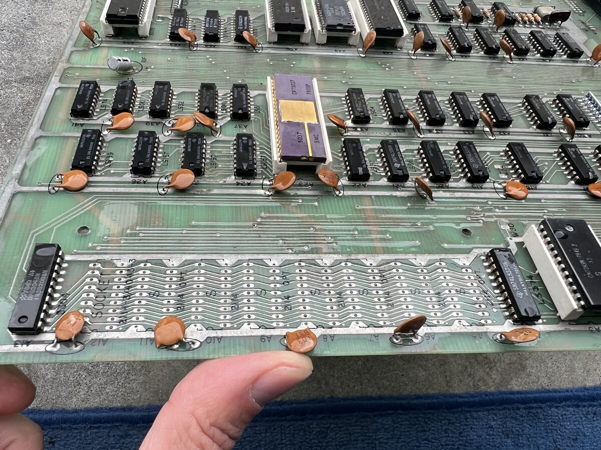
The board looks quite good after this.
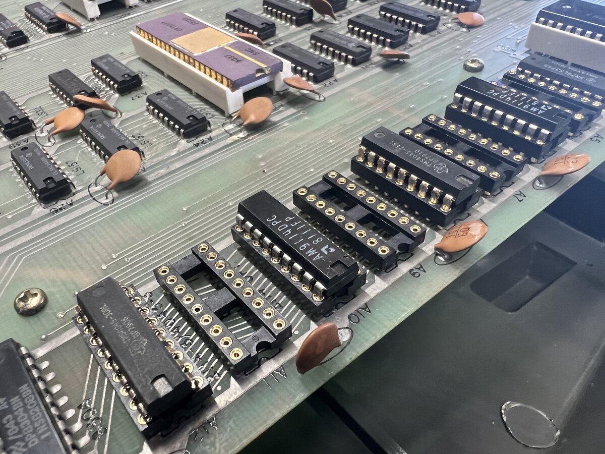
The process of soldering the new sockets was quick and easy.
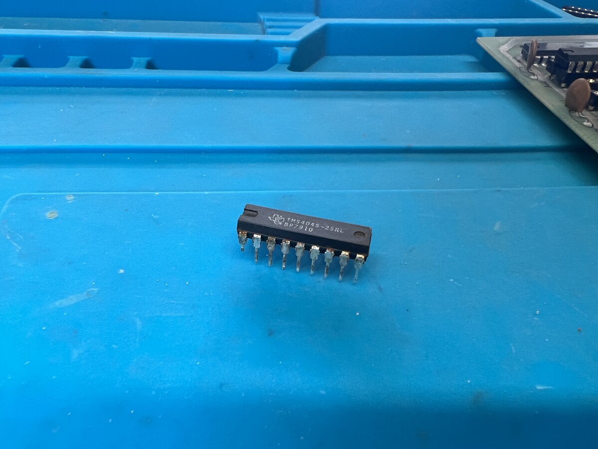
However, while putting back the memory chips, the pin of one of the original ones broke. The pins show a lot of corrosion, with plating peeling off. I am keeping that chip for now as a spare, as it could be fixed if needed, but I put in one of my 3 “new” spare chips in the machine.
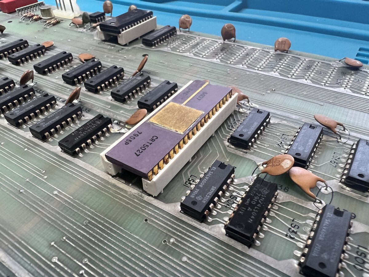
The ICs in their new sockets look pretty good!
CRT
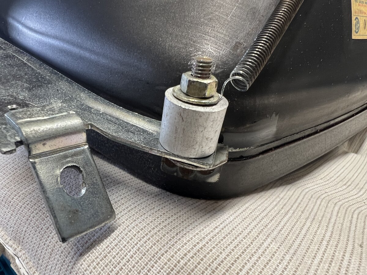
I originally didn’t have to take out the CRT. But since I had removed that spring for derusting, I had to put it back, and it was hard to do so correctly with the CRT attached to the top case. So I had done it quickly but not perfectly, and I wanted to come back to it to properly secure the spring.
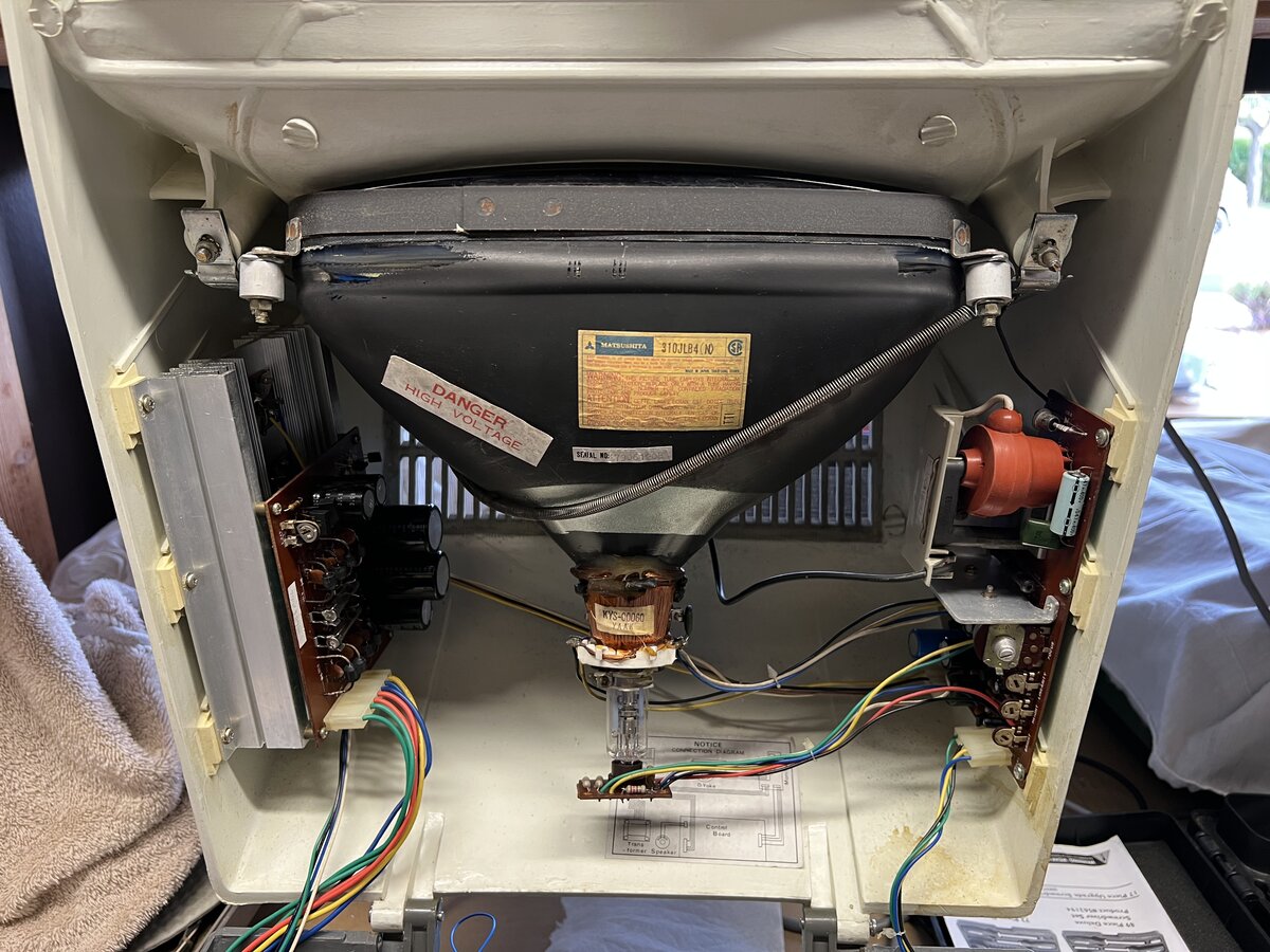
So I removed the CRT from the case, which is easy with to nuts at the top. I did this after, again, discharging the anode, and this time I definitely had a nice “pop” (or “zap”).
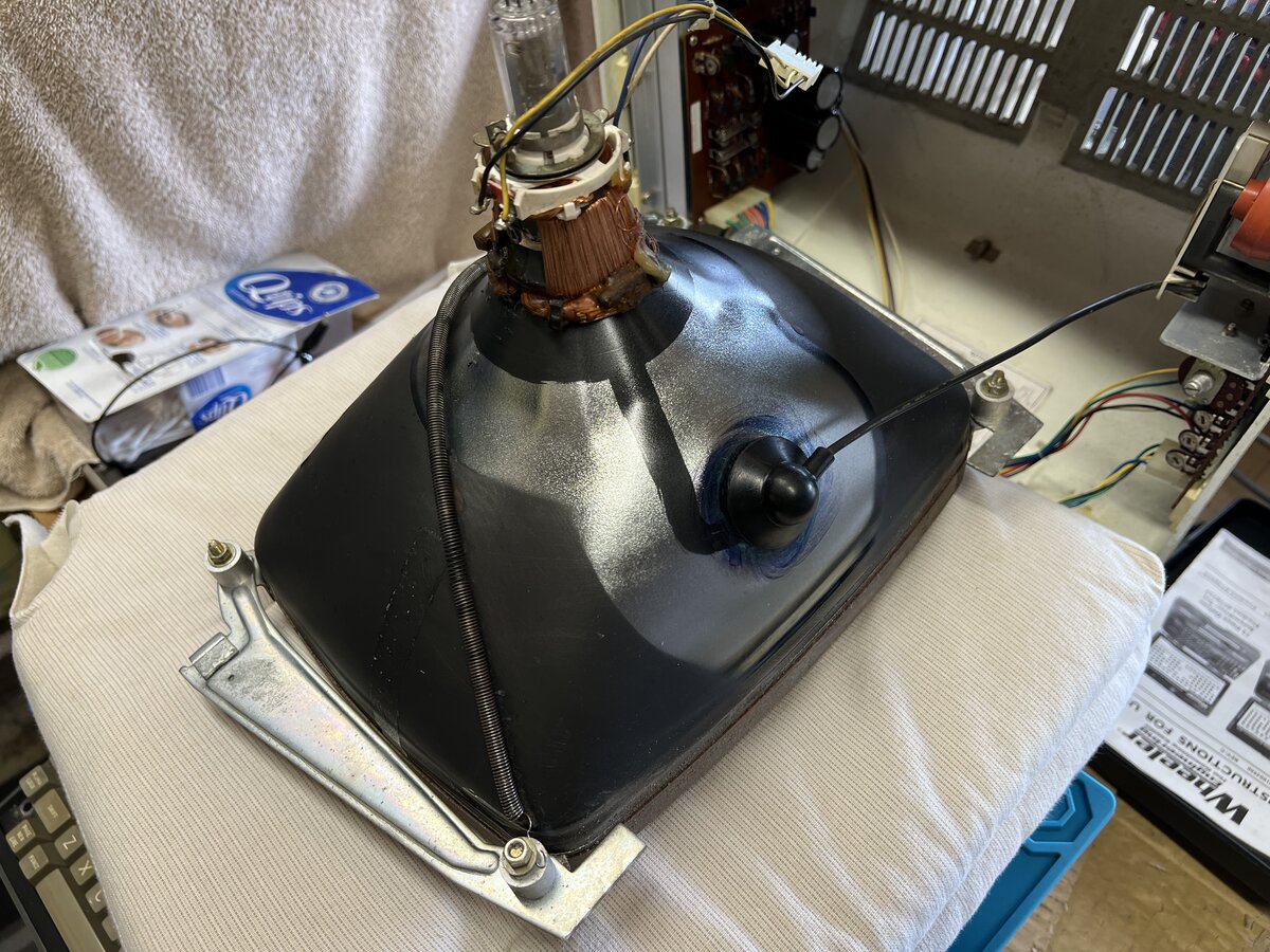
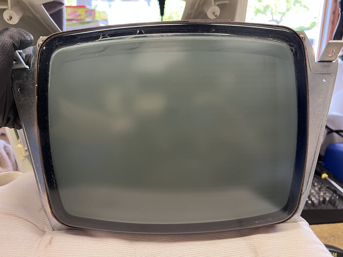
This also allowed me to properly cleaning the glass.
I reattached the spring correctly.
Finally, I put the CRT back.
Keyboard
The last big part to handle was the keyboard. It worked, at least in part, but it was dirty.
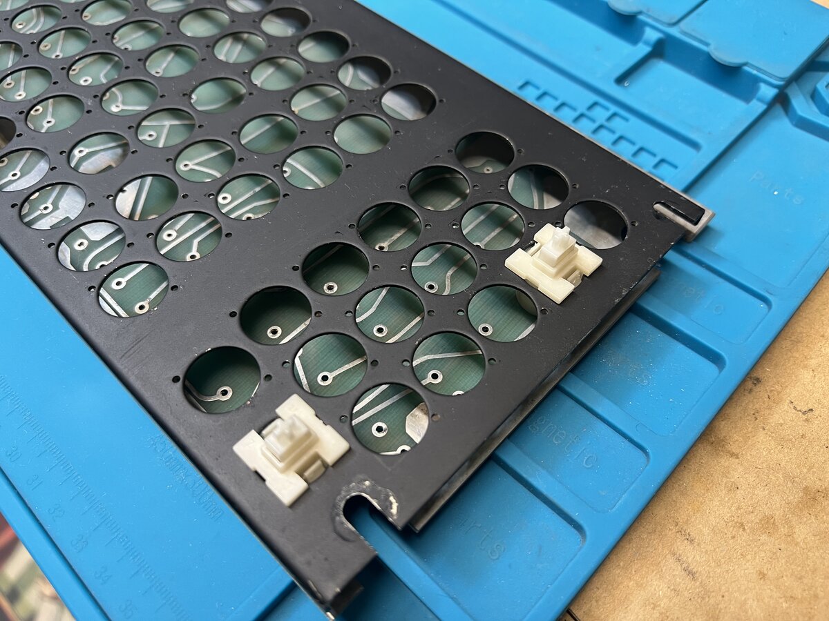
The keyboard is made of a PCB, individually-soldered switches, and a large metal plate - like modern “mechanical” keyboards. In the video series on YouTube already mentioned, the author removes all keycaps with a keycap puller, and then desolders all switches for in-depth cleaning! I gave that a quick try removing the keycaps with a keycap puller.
Inspired that video, I proceeded to:
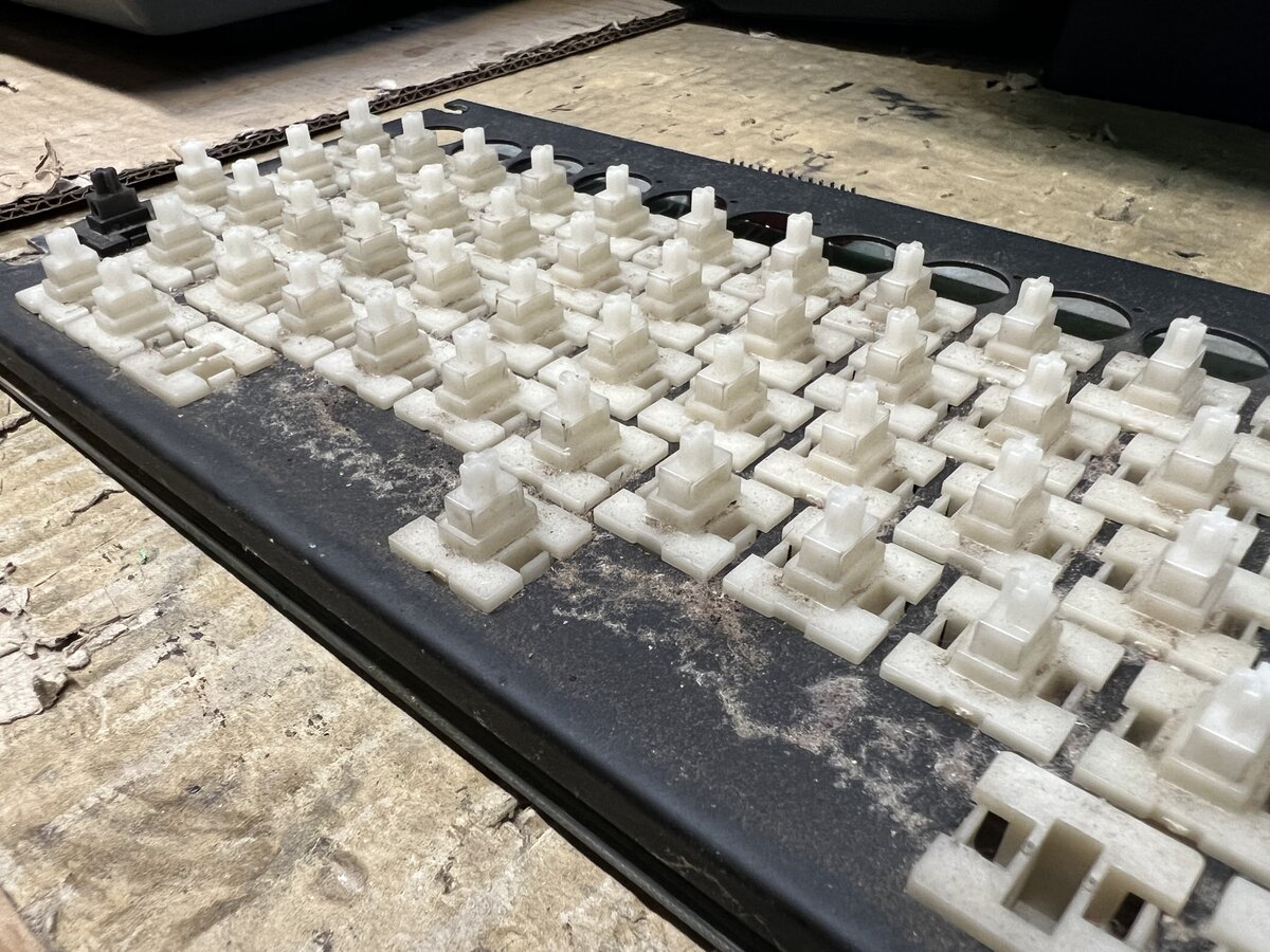
- Remove all keycaps
- Desolder all switches
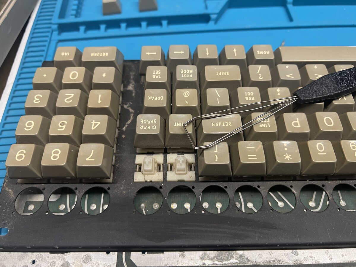
Removing the keycaps went ok, except that I ended up breaking the inside of two of them. That part appears fragile and I went a little hard or too quickly. You can see the sticky dust underneath.
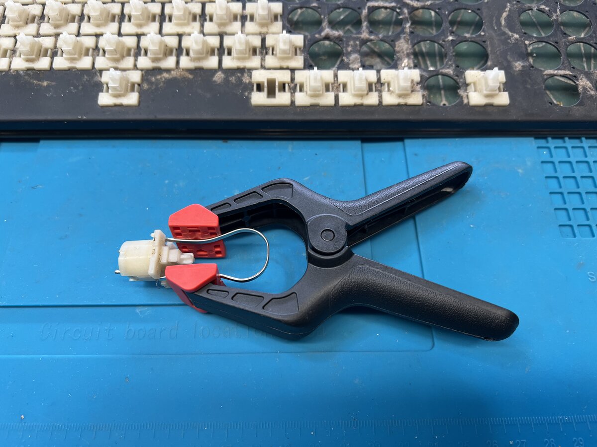
For desoldering, I used my hand solder pump. This made the process longer and more painful than with an electric pump, but it worked. In order to pull out the switches from the plate individually, you have to push the two side tabs. I devised a little helper for that.
I struggled a little with some individual switches and I had to reapply heat. In general, you don’t want to apply too much heat to components, including switches, so I tried to be careful.
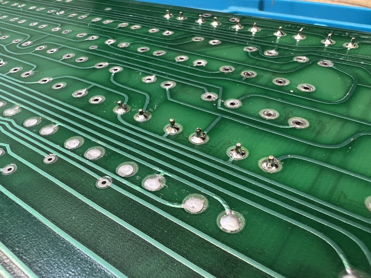
The PCB was dirty underneath the switches.
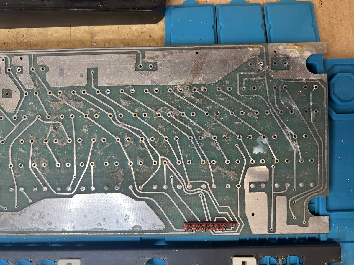
I then cleaned the PCB entirely with soapy water, then distilled vinegar (to lightly remove corrosion), and finally alcohol to remove old flux. The PCB looked pretty good after that.
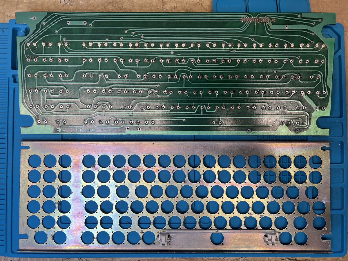
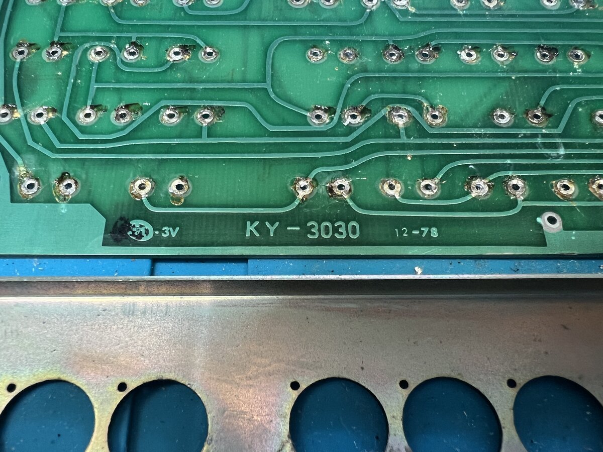
The PCB bears the date of 12-78, which points to December 1978.
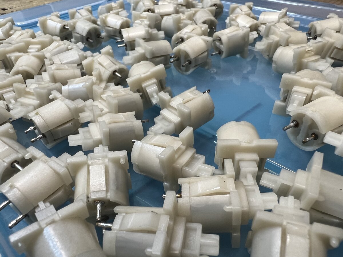
I also cleaned all the switches.
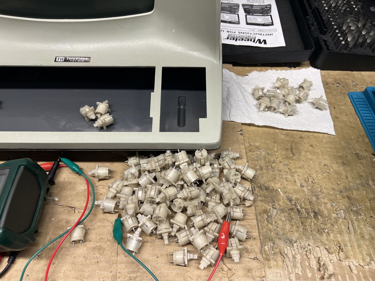
I didn’t want to immerse them, so I cleaned each of them by hand with a damp microfiber cloth. They look pretty good after cleaning.
I measured a few of the switches, but not all of them. Of course, in retrospect I should have tested all of them, see below!
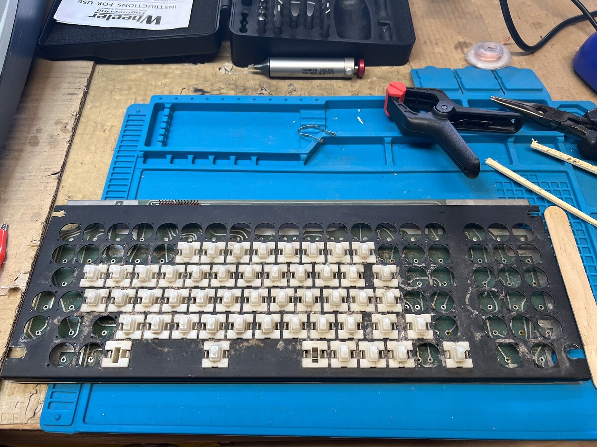
Then I started resoldering the switches.
I kept only two switches in their original position: the space bar switch, and the caps lock switch, which happened to be black. I tried to do a good job soldering.
Once done, I proceeded to test the keyboard. Alas, some keys didn’t work! I identified two problems:
- The ribbon cable was faulty and caused some of the issues. Playing a little with the cable solved that, but it would be worth replacing the cable and/or connectors.
- Some switches still didn’t work after that. I desoldered two of them, measured them, and indeed they didn’t work even out of the PCB!
I don’t know why those switches didn’t work: I should have systematically measured them before desoldering them, but that was too late for that. In addition, I didn’t put the switches back necessarily to their original location. I figured I had little to lose and applied contact cleaner inside. I doesn’t look like you can disassemble those switches, so I let the cleaner seep through on the side of the switches’ stem. Luckily, after activating the switches a bunch of times they eventually started working!
They might have been bad in the first place, possibly due to corrosion or dust inside, or the heat I applied for desoldering and soldering might have caused the problem, I don’t know. I am just glad that they work now. I identified two more switches with issues and applied contact cleaner in place without desoldering. I don’t think things are perfect but the keyboard works well enough now.
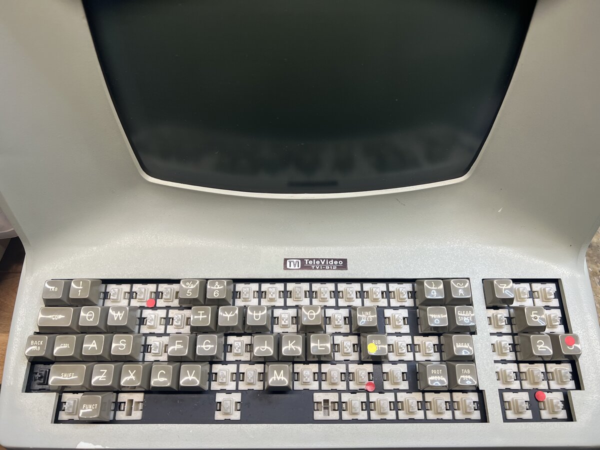
Finally, I got all keys working, although I think that the “3” on the numeric pad is a little sluggish, and 2 switches produce two characters if you press the key down very slowly. More cleaning might help with that, who knows.
Now I had to tackle the broken keytops. Two were damaged while removing them, and a third one was damaged while I was debugging the keyboard.
I first tried superglue. But as soon as I pressed the key on the stem, it broke again. So I resolved to use JB Weld Clear, and to fill the space inside the keytop around the round part. Surely this will hold until the end of times! So I did just that.
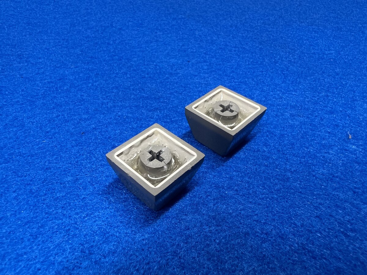
The main issue was to remove leftover superglue from the inside of the cross. I ended up using an X-Acto knife to do that. It eventually worked and I was able to press the keytops down onto their stems.
Now, honestly, I can’t say whether it was wise or not to embark on that whole desoldering/resoldering process. I considered cleaning underneath the keys a necessity, but there might have been other ways. This was just the clearest way to proceed. But in any case, I should have measured and tested all the switches beforehand as well as after desoldering, to understand better whether my process caused new issues with the switches or not.
Stickers
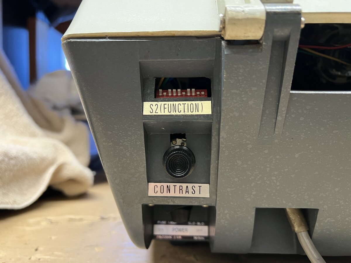
The TVI-912 has metal “stickers” in the back to label the DIP switches and buttons. When I got this terminal, one of them was peeling off, and two of them had fallen off, but they had been neatly packed in a ziploc bag, and so I had them.
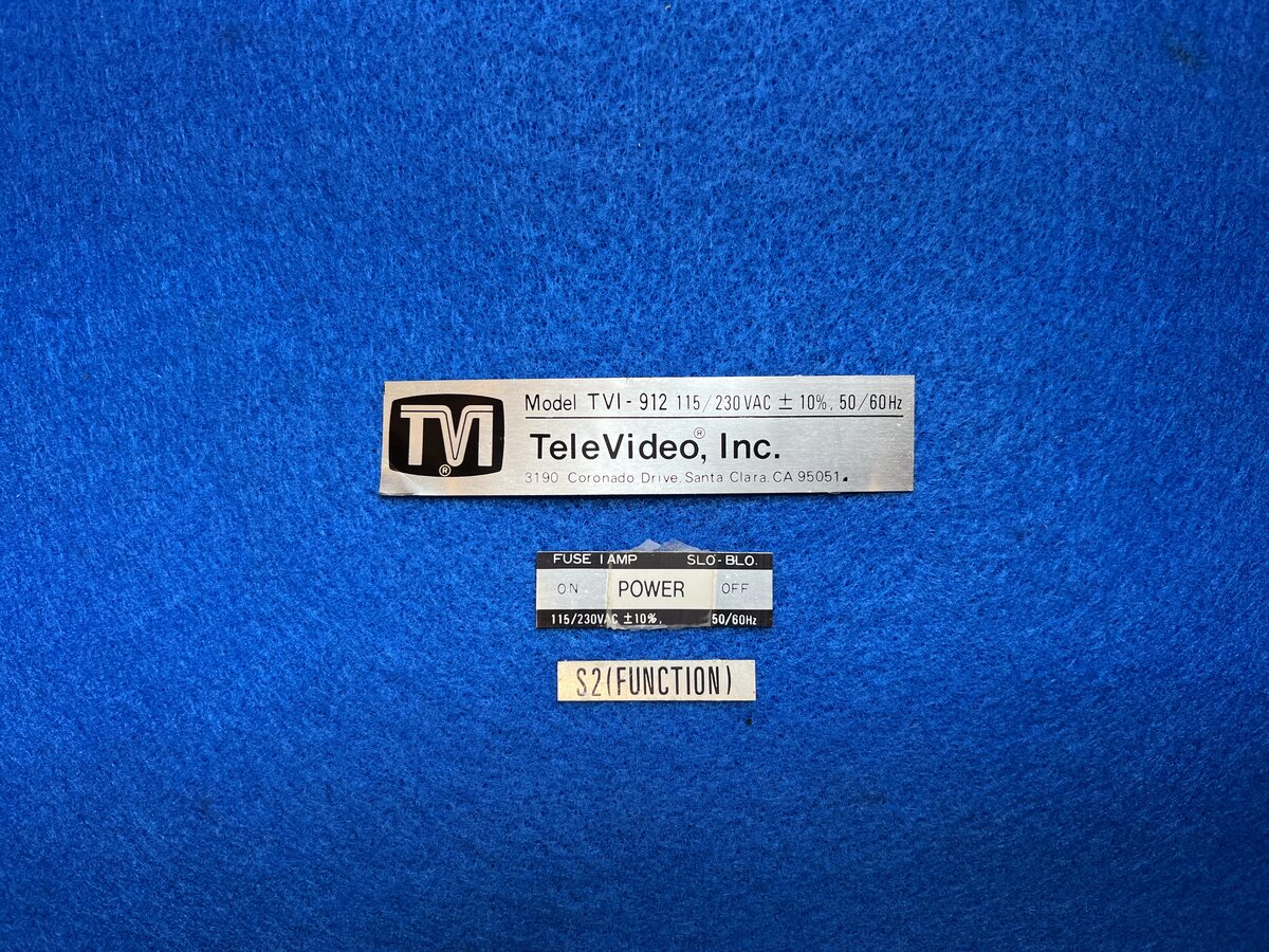
I cleaned all of them with Goo-Gone, and scraped off the peeling laminate.
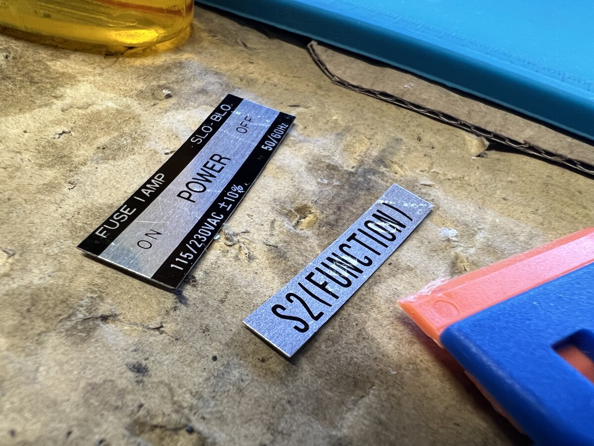
Finally I glued them back.
Misc stuff
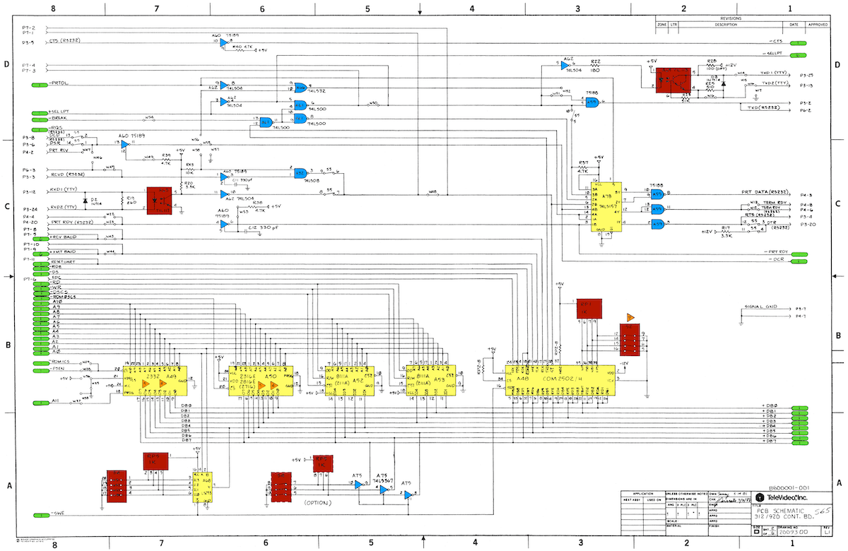
Cleaned schematics
I produced a colorized and slightly cleaned version of the 5 pages of schematics! I used the Super Resolution function of Pixelmator Pro before getting the documents printed. This smoothes the original black and white scans to a good degree.
Original manual
I managed to buy an original manual to go alongside the terminal.
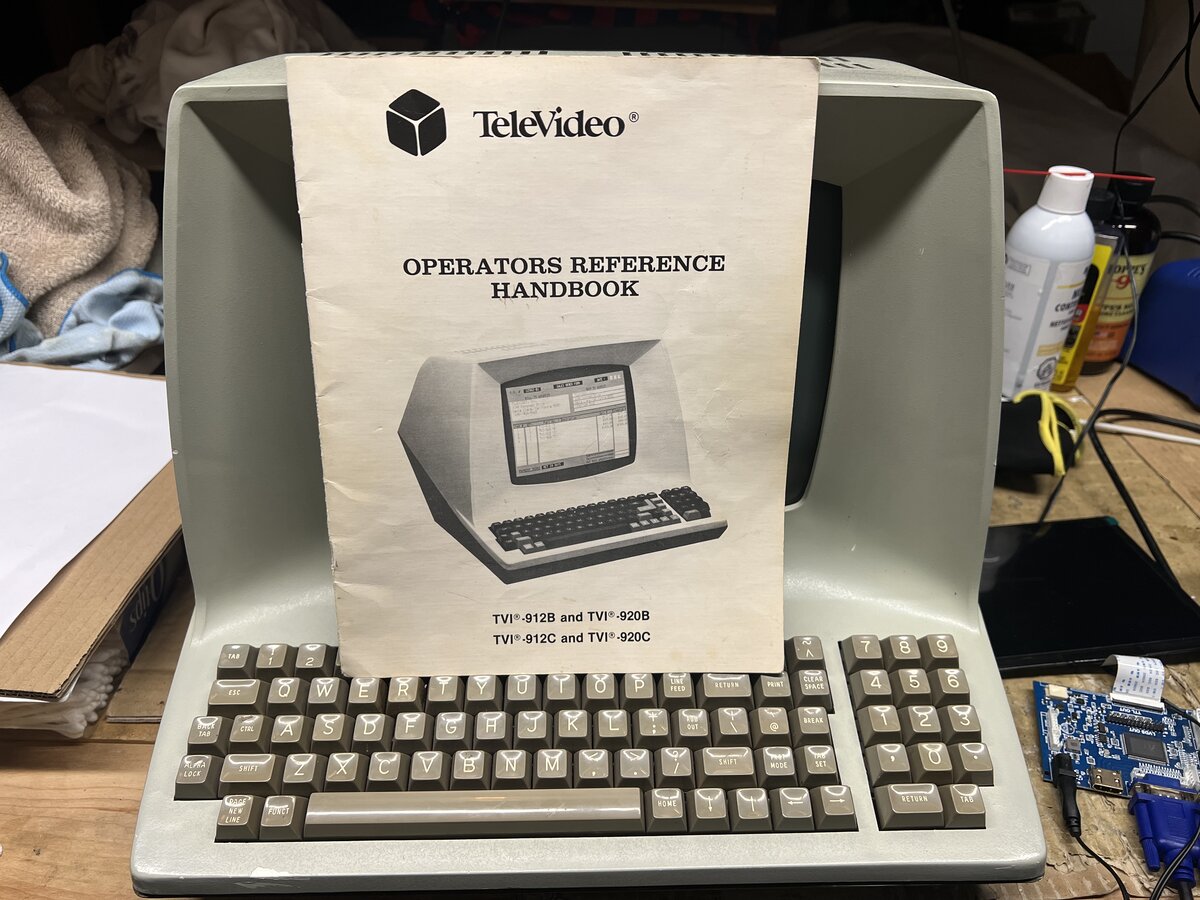
This is nice, even though, as discussed in my first post, there are already several scans of this manual available online. I might yet scan this one at high-resolution to add one more option.
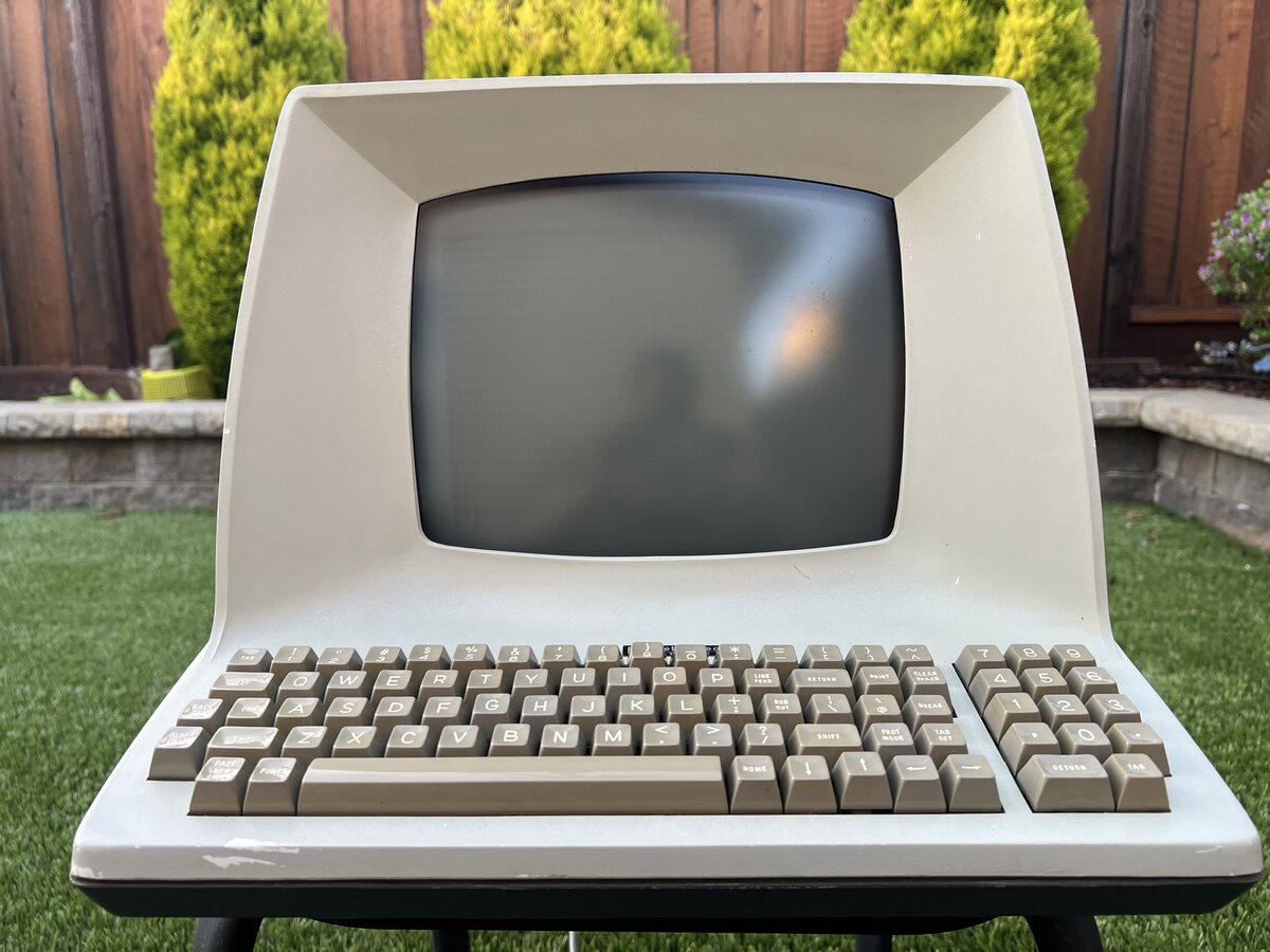
Restored terminal
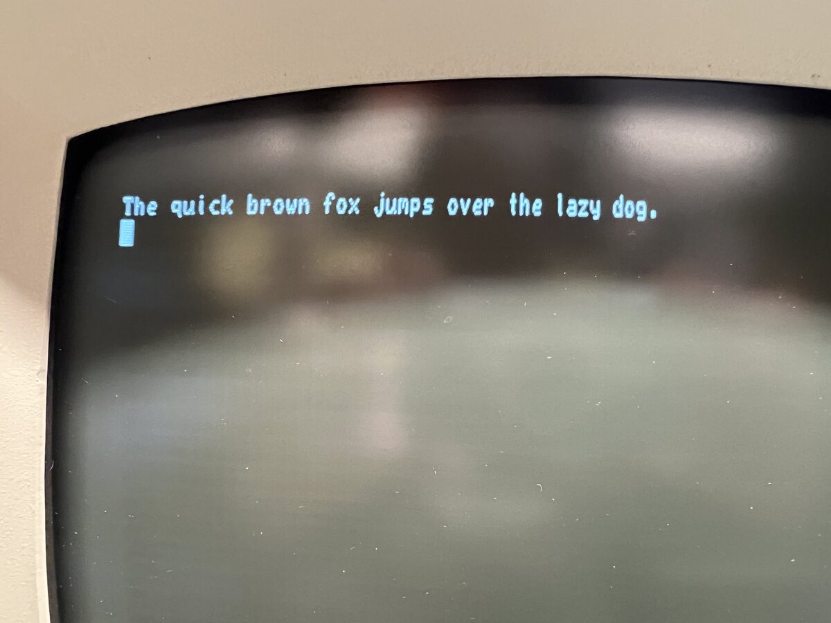
The terminal looks very good now.
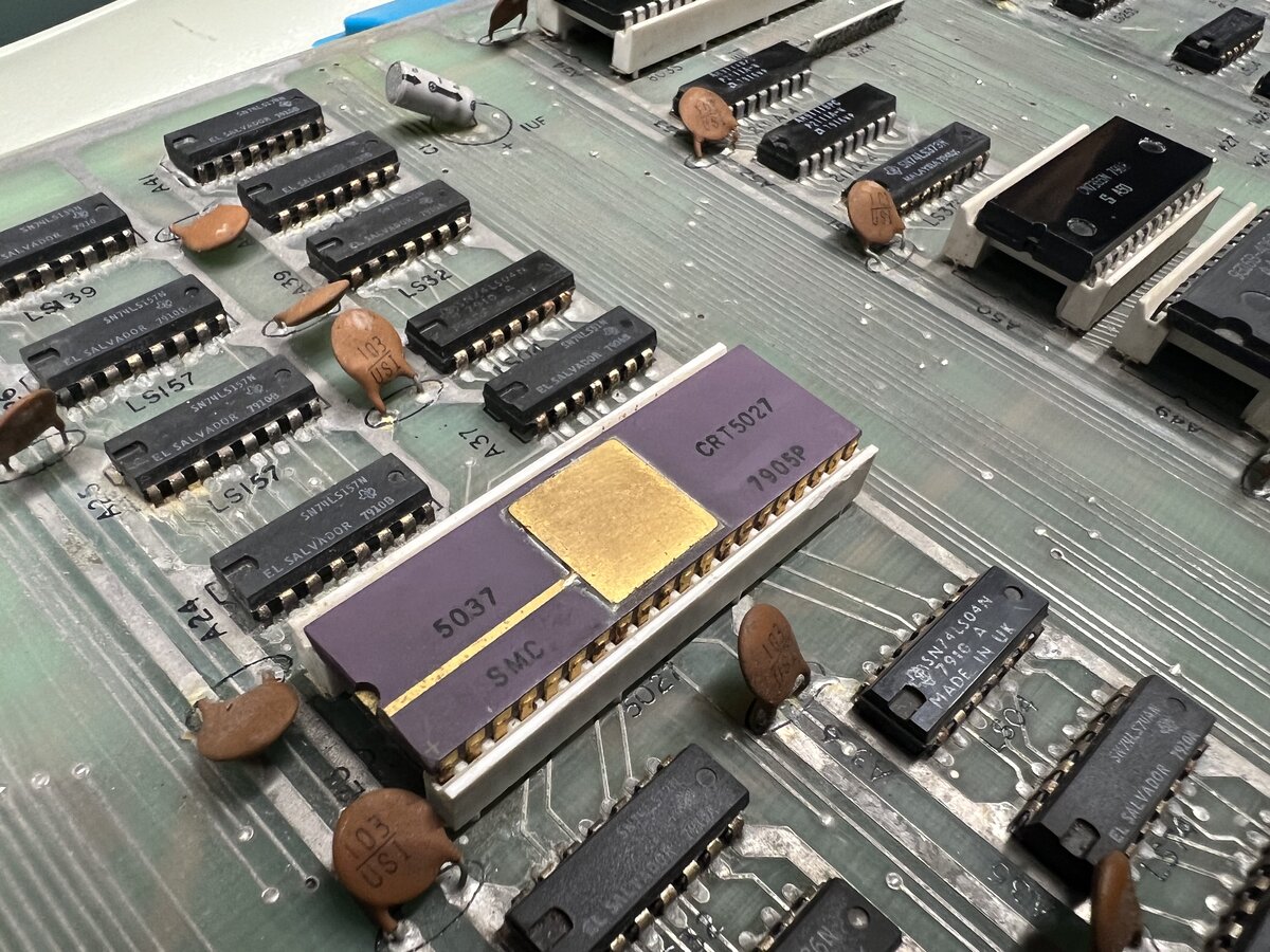
I don’t get tired of the neat CRT chip.
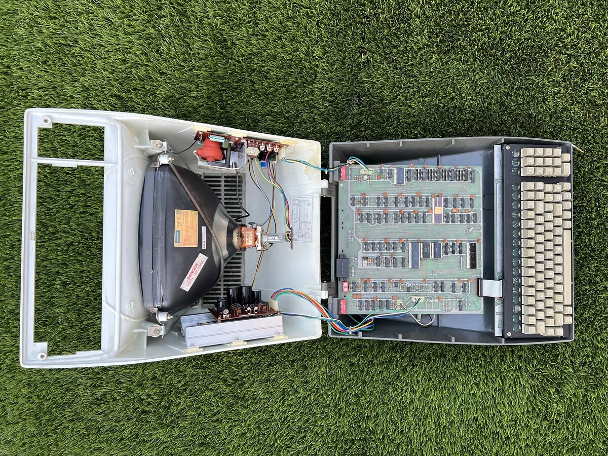
Here is a view of the fully open “clamshell”1 case.2
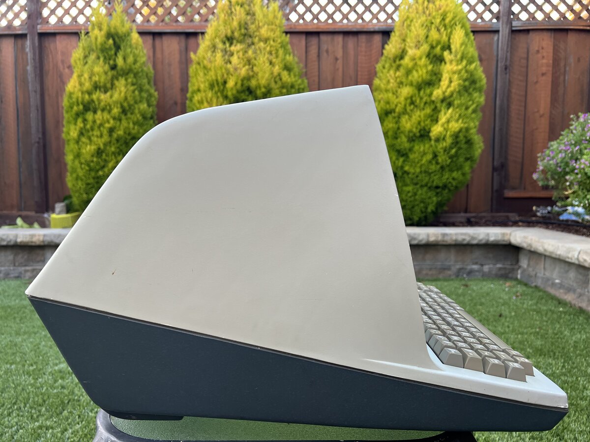
The iconic profile of the early TeleVideo terminals.
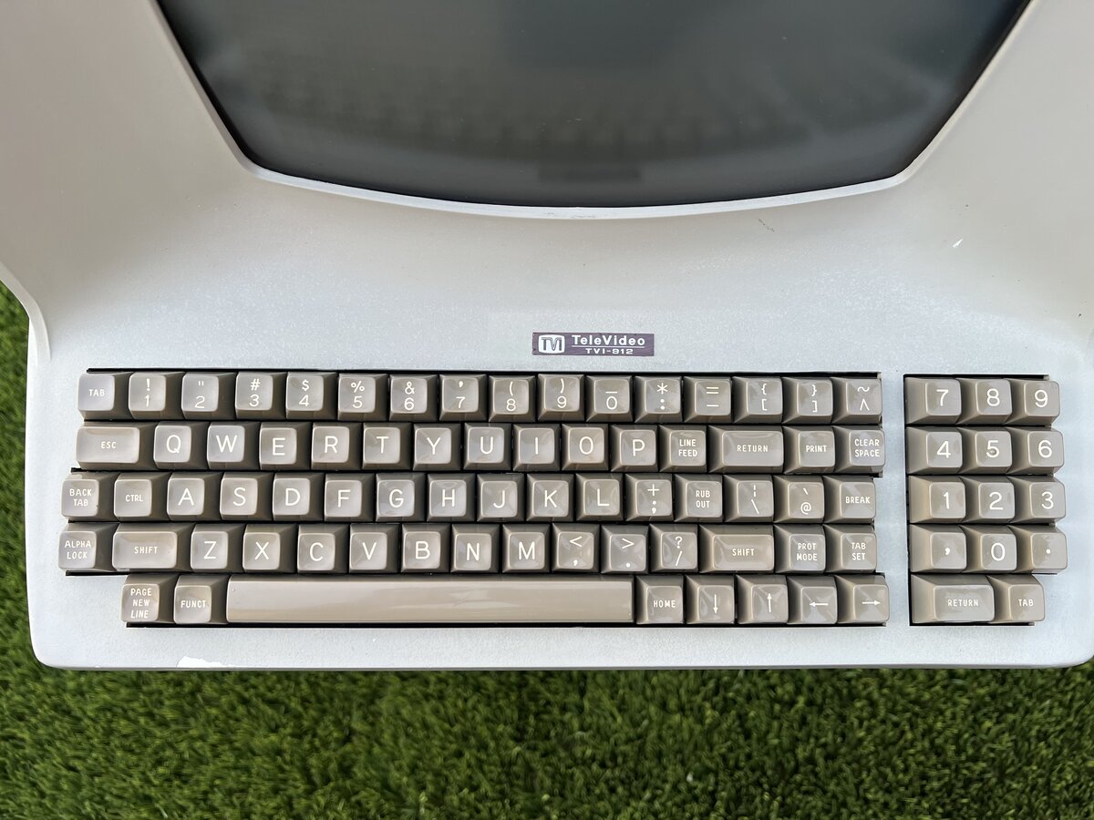
The teletype-style keyboard.
Next steps
ROMs
There are already ROM dumps online, but I’d like to dump my 3 ROMs for posterity and to compare. You never know, there can be some difference, including bug-fixes. If I do this, I might replace the ROM sockets, we’ll see.
- http://www.bitsavers.org/pdf/televideo/912/firmware/
- http://www.peel.dk/Televideo_920/
- https://www.planetemu.net/rom/mame-roms/tv910 (Model 910)
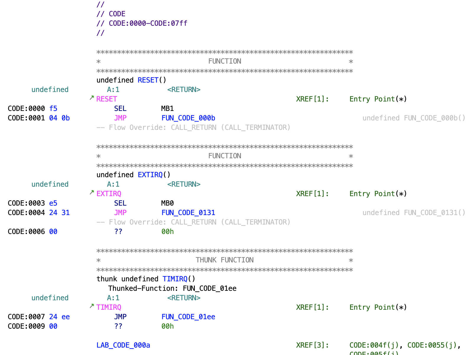
It would be fun to reverse-engineer the firmware! I tried feeding the ROMs to a disassembler, and something comes out, but I am sure there would be a lot of work to do to make sense of it.
CP/M and more
I’d like to play with the terminal with CP/M on the Altair-Duino, and also try to connect the terminal to my PiDP-11, another neat kit.
I’d also like to play with software aspects. The manual describes how you can set the terminal to move the cursor, output inverse video, underline, etc. It’d be neat to explore the relatively limited capabilities of the TVI-912, directly or via terminfo/ncurses.
Further work
It would be good to do the following:
- investigate why the 9600 bauds mode doesn’t seem to work
- fix or replace the keyboard’s ribbon cable
- consider light paint touch-ups on the case top, as there are chips
- consider making a cover for the back of the terminal, around the RS-232 connector, as I am pretty sure there must have been such a cover originally
See also
- The TeleVideo TVI-912 terminal - Part 1
- The TeleVideo TVI-912 terminal - Part 2
- Photo album: Televideo TVI-912 terminal (1979) - Part 1
- Photo album: Televideo TVI-912 terminal (1979) - Part 2
- Photo album: TeleVideo TVI-912 (1979) - Restored
Update 2023-10-04: I have since learned that the design of the 912 was inspired, not to say copied, from that of the iconic Lear Siegler ADM terminals. ↩
I noticed that the later TVI-910 has a much smaller main board, taking about half the size of the case. ↩
Comments powered by Disqus.