
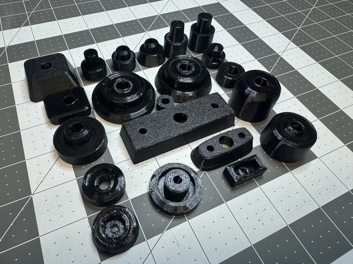
Why 3D print typewriter feet?
Typewriter feet do more work than they usually get credit for:
- They keep the machine from sliding across smooth desks when typing or returning the carriage.
- They dampen vibrations and noise, making typing quieter and more comfortable.
- They protect both the desk surface underneath and the typewriter itself from scratches and dents.
To do all three jobs, feet need to be relatively soft and grippy, which is why they were traditionally made of rubber. Over the decades, however, rubber ages poorly: on most vintage machines, the original feet have turned rock-hard, flattened, crumbled away, or gone missing altogether. You could reasonably view typewriter feet as consumable parts - much like platens, or car tires.
Most typewriter manufacturers are long gone, and original replacement parts haven’t been made in decades. Until recently, the usual workarounds were:
- keeping the hardened feet and placing the typewriter on a mat;
- substituting generic hardware-store parts such as rubber furniture feet, bumpers, or lab stoppers;
- sculpting replacements out of moldable rubber like Sugru; or
- buying modern replacement feet from specialty typewriter-parts sellers.
That last option is very real, and some of the custom-poured rubber feet sold today are wonderfully made. Over the years, I have personally spent hundreds of dollars on them. The catch is twofold: at USD 20–40 per set, they get expensive fast, and you are limited to the relatively common models on offer. Across a large collection - including rare 19th- and early-20th-century machines for which no aftermarket feet exist, as well as unrestored project or parts machines sitting in storage - buying poured rubber sets for everything simply isn’t practical.
Once I got a 3D printer, designing and printing my own replacement feet turned out to be a game changer. Starting with a single test for a 1920 Underwood 5, I quickly ended up designing feet for over twenty machines spanning eight decades of typewriter history.
Choosing the right material: Shore 85A TPU
PLA and PETG, the workhorse filaments of hobbyist 3D printing, are poorly suited for actual typewriter feet: they are far too hard and slippery. TPU (thermoplastic polyurethane), on the other hand, is a flexible elastomer filament sold in varying hardness grades on the Shore A scale.
The most widely available flexible filament is Shore 95A TPU. I tried it first, and while it works fine for static display, I found it too stiff and not grippy enough for real use. Switching to a softer Shore 85A TPU - specifically Siraya Tech Flex 85A - made all the difference.
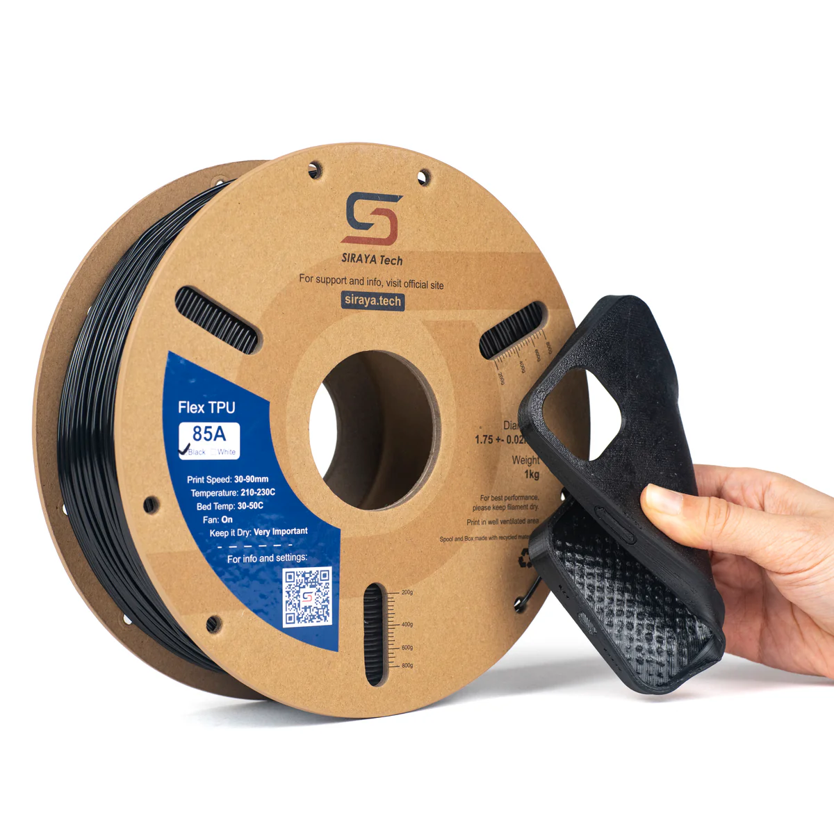
In terms of bounce and cushioning, Shore 85A TPU is excellent and feels very close to rubber. You can also tune the effective firmness of a foot by varying the slicer infill - I have used anywhere from 100% solid down to about 25% depending on the thickness and geometry of the foot. While TPU is still slightly less tacky than fresh natural rubber, the weight of a typewriter makes up for it in practice, and it is worlds better than missing, petrified, or crumbled feet.
Color choices are much narrower in soft TPU than in PLA or PETG: black is by far the most common, alongside white, clear, and the occasional bright color like orange. Fortunately, black is perfect for almost any typewriter.
Printer setup for soft TPU
Soft TPU has a reputation for being finicky, though modern printers handle it much better than older machines did. Still, Shore 85A is floppy enough that I couldn’t push it reliably through my printer’s PTFE guide tube. Instead, I feed the filament straight into the top of the extruder - a setup made easy by an earlier modification allowing me to lift off my printer’s top cover.
Initially, I ran into a few extruder jams, likely triggered during filament retractions. Tweaking the tension screws on the extruder idler largely eliminated those jams. Equally important, TPU is hygroscopic and must be dry to print cleanly: a filament dryer is essential, and I feed the spool directly out of a dry box onto a textured build sheet so it doesn’t absorb moisture mid-print. The short video below shows that setup in action:
From petrified rubber to CAD
Before a new foot goes on, the remnants of the old one have to come off. When the original rubber was molded into a metal cup, removing it can be surprisingly tricky: the cups are often stamped out of very soft steel or brass that bends easily if you pry too hard. On a couple of machines, the aged rubber was so hard that I actually used a drill to bore it out, escaping with only minor scratches inside the cups.
Once the mounting hardware is clean, the design loop itself is fast and satisfying:
- Inspect what remains of the original foot, mentally (or on paper) reconstructing its un-flattened profile.
- Measure key dimensions - cup inner diameters, stem holes, screw clearances, and frame offsets - with digital calipers.
- Model the part in CAD (I use Autodesk Fusion).
- Print a quick test piece in PLA to verify the fit against the hardware and frame, adjusting dimensions as needed.
- Refine and print in Shore 85A TPU, adding fillets and chamfers for appearance and printability.
Here is that PLA prototyping step for my very first design, the 1920 Underwood 5, showing the rock-hard original foot on the right and the orange PLA test print on the left (both viewed from underneath):
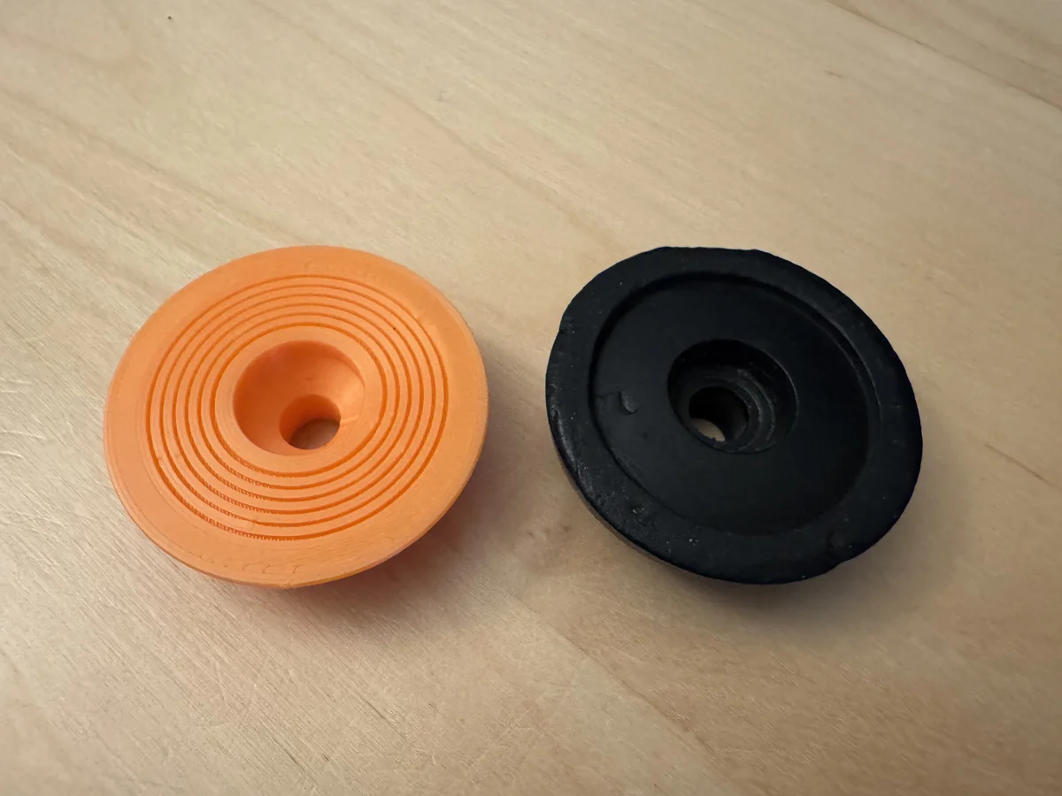
One important 3D-printing constraint is avoiding supports. Overhanging cavities normally require sacrificial support material, which is messy to remove cleanly from flexible TPU (unless you have a multi-material setup printing PLA supports). By using angled internal chamfers and concentric bottom grooves instead of flat unsupported overhangs, none of the feet I have designed so far require supports.
Designing across eight decades of typewriters
What surprised me most after doing the Underwood 5 was just how differently typewriter makers approached mounting four pieces of rubber to a frame between the 1880s and the 1960s. Grouping my designs by attachment style and geometry gives a nice tour of both typewriter engineering and CAD techniques.
1. Press-fit stems, reinforcing rods, and clearance notches (1885–1917)
The earliest feet in my collection were also the simplest to model: stepped cylindrical plugs that press-fit directly into round holes in the cast-iron base, as on the Remington 2 (1885), Densmore 1b (1894–1896), and Smith Premier 5 (1907).
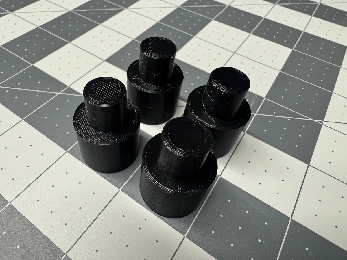
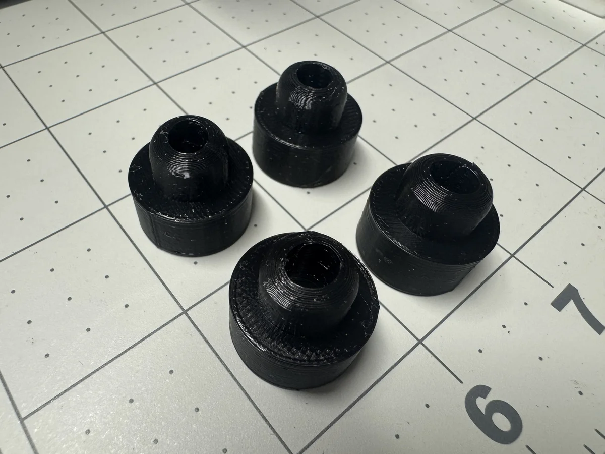
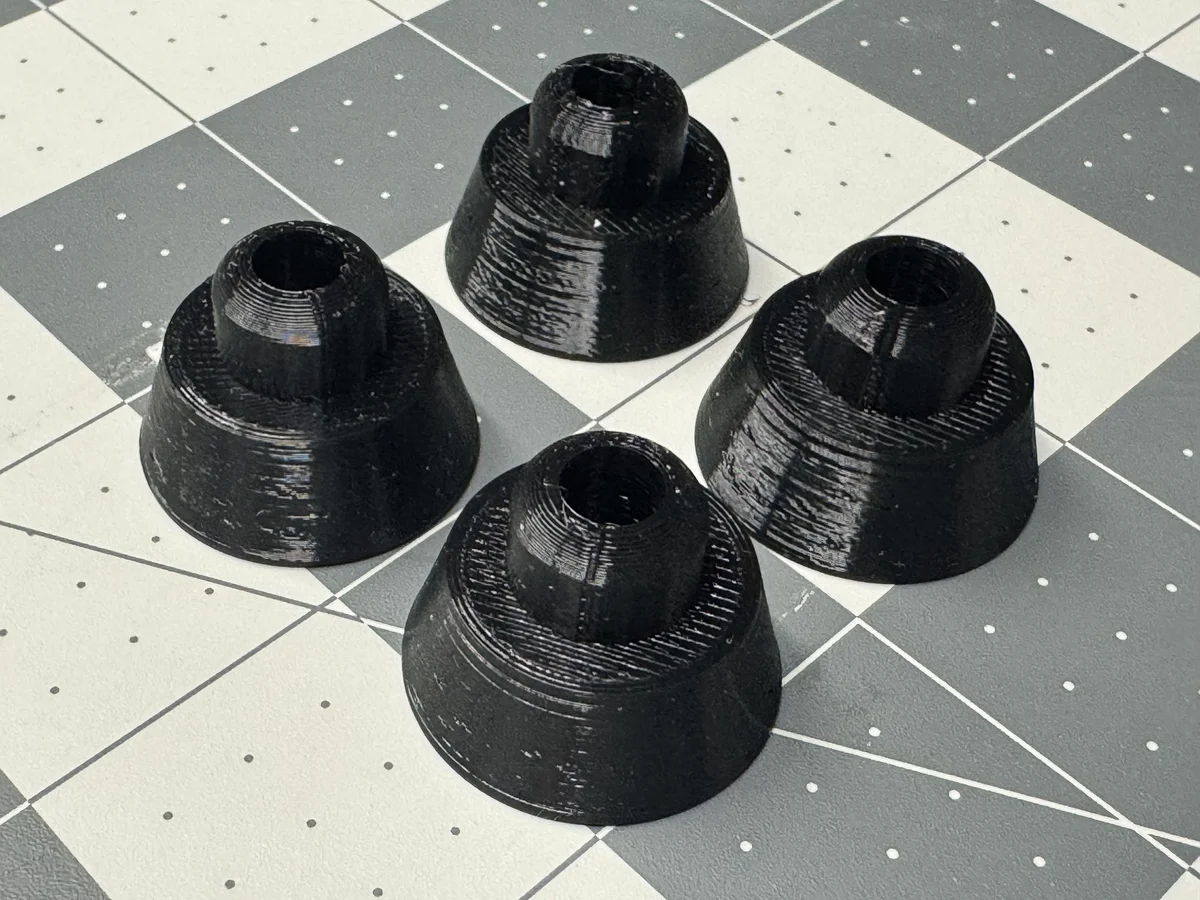
Because CAD makes experimentation nearly free, I tried two variations for my 1899 Densmore 4 (whose feet are secured with screws): a straightforward cylindrical profile - likely closer to what left the factory - and a tapered conical version just to look a little more snazzy.
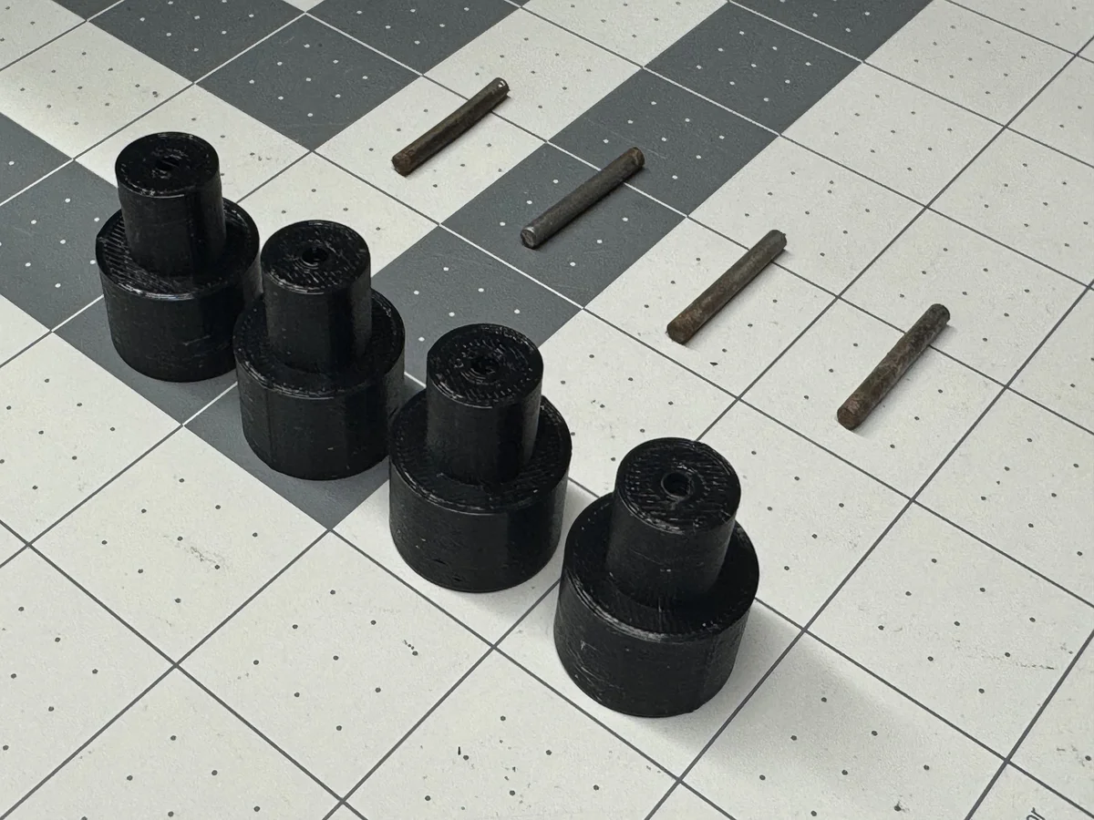
The tall push-in feet on my 1907 Remington 7 with Gorin tabulator look similar from the outside, but hide a neat structural detail: an inch-long steel rod slips into the center of the foot to stiffen and stabilize it. Preserving that internal bore in the printed TPU version (alongside a tapered variant) was trivial.
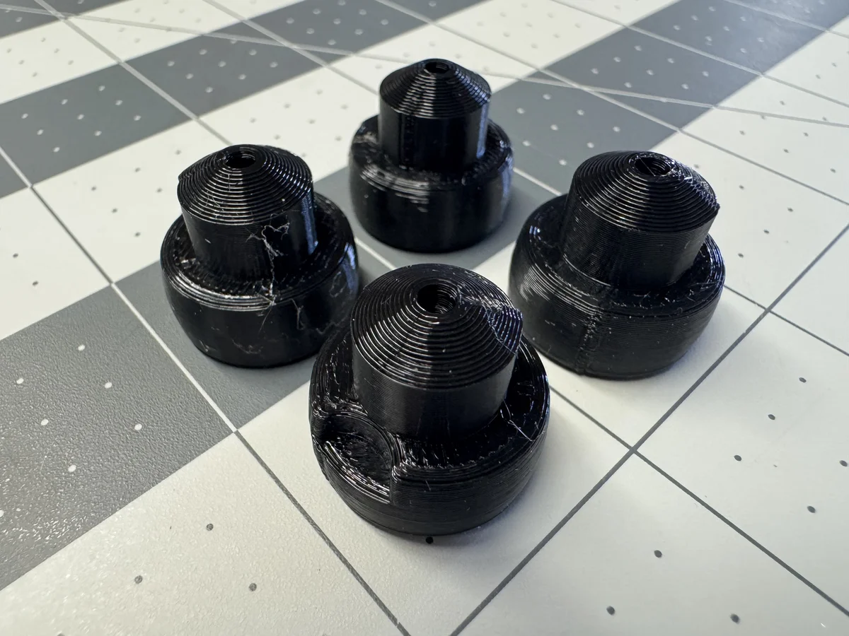
Custom CAD also shines when a machine needs an asymmetric tweak. My 1909 aluminum Blickensderfer 5 arrived with only two deformed, fossilized feet remaining; years ago I had sculpted makeshift rear feet out of Sugru, with mediocre results. While modeling proper rounded TPU replacements (with top holes for slotted wood screws), I noticed a screw head on the underside of the frame encroaching on the left rear foot - and added a clean clearance notch in minutes:
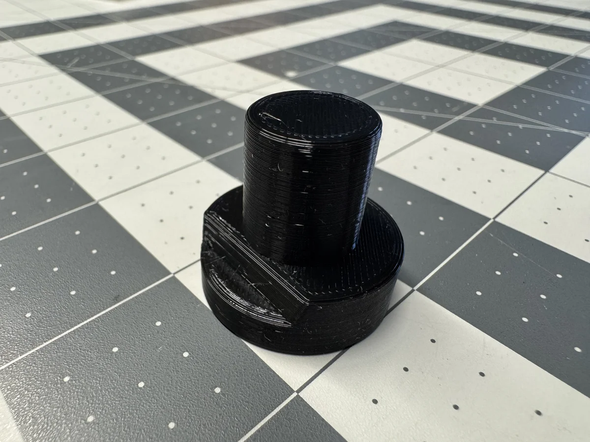
I took a similar approach on my 1917 Courier - essentially an Austrian-built Oliver 3 (so the part may fit an Oliver 3 as well). Here the feet press directly into the frame without hardware, and adding a stepped side notch let me make the base slightly oversized, reaching just beyond the cast-iron body for a wider, more stable footprint:
2. Metal cups, screw studs, and multi-part cushions (1906–1949)
By the 1910s and 1920s, many standard office machines seated their rubber feet inside stamped metal cups held to the frame with screws. That includes the screw-in feet on the Royal “flatbed” Models 1, 5, and 6 (which can be printed shorter or taller depending on preference), the tall stocky cup-mounted feet of my 1920 Underwood 5, and the wide cup-mounted feet of the 1920s Remington Vertical Adder Model 21 (which likely fit contemporaneous Remington standards as well).
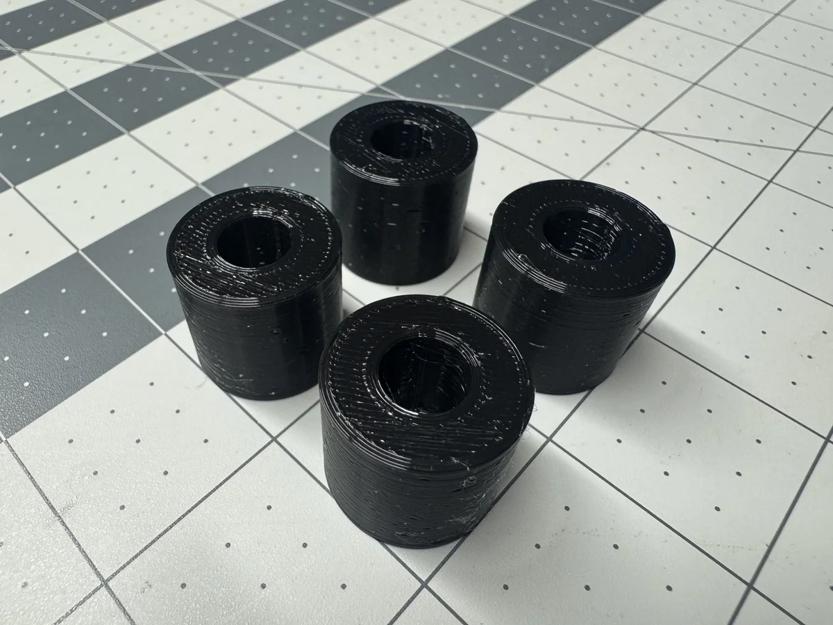
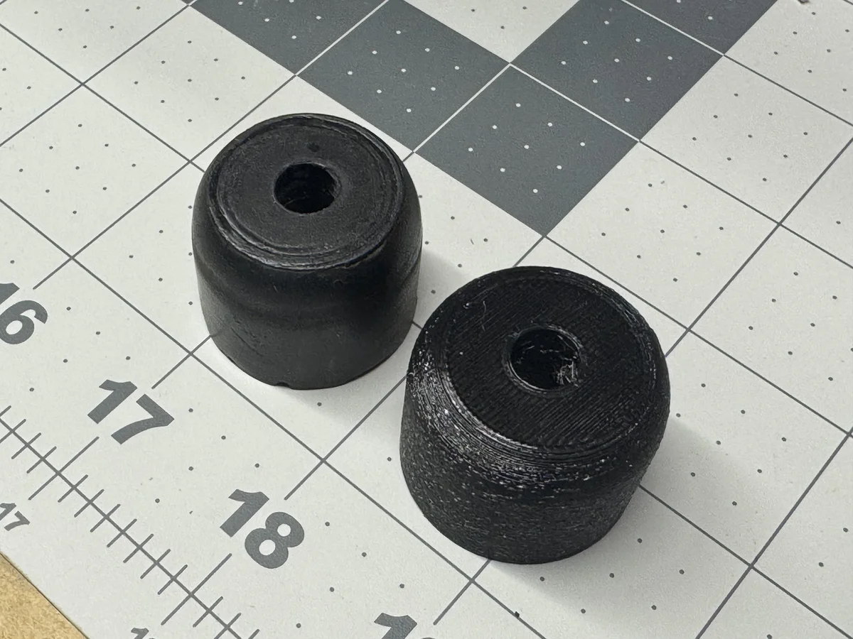
By the late 1930s and 1940s, vibration isolation became more sophisticated. The 1938 Royal KHM sandwiches the mounting hardware between the main square-ish foot below and a separate rubber rebound cushion on top:
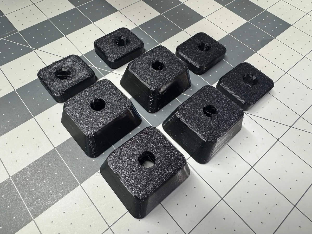
Postwar Underwoods evolved along similar lines. On my 1942 Underwood “S”, the rubber sits beneath felt-like cushions inside metal cups; I made the hidden soft TPU section slightly taller than the flattened originals without changing the external look. The 1948 Underwood “SS” and 1949 Rhythm Touch use wider saucer-like feet that may originally have shared the same molded rubber part, though on my machines the Rhythm Touch hardware includes an extra metal insert and washer. I modeled slightly straighter walls for the Rhythm Touch and gave both designs grooved undersides and internal chamfers so they print cleanly without supports.
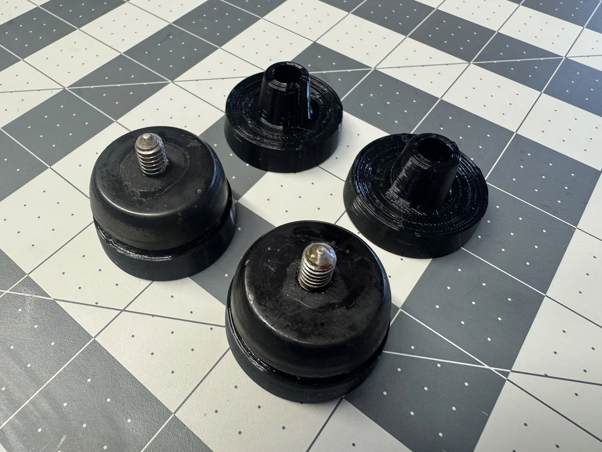
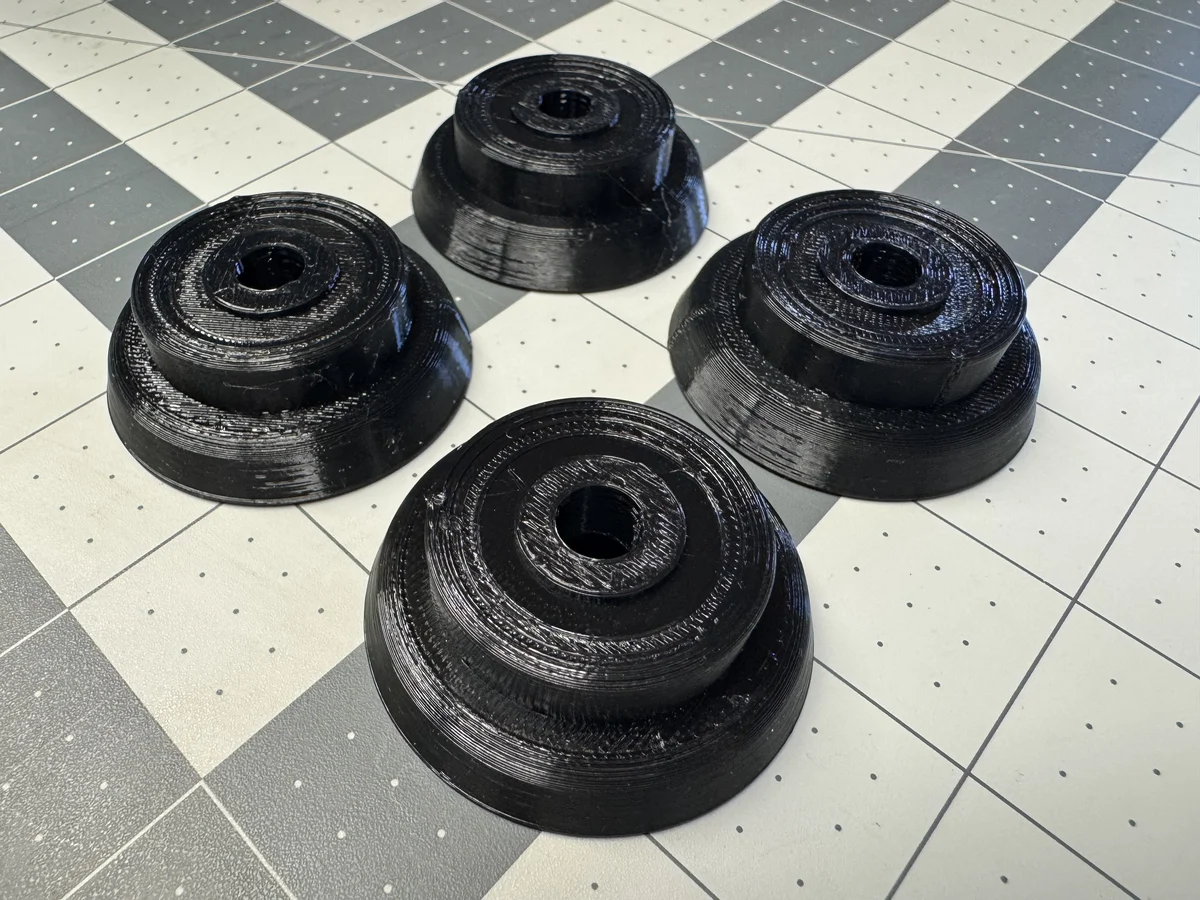
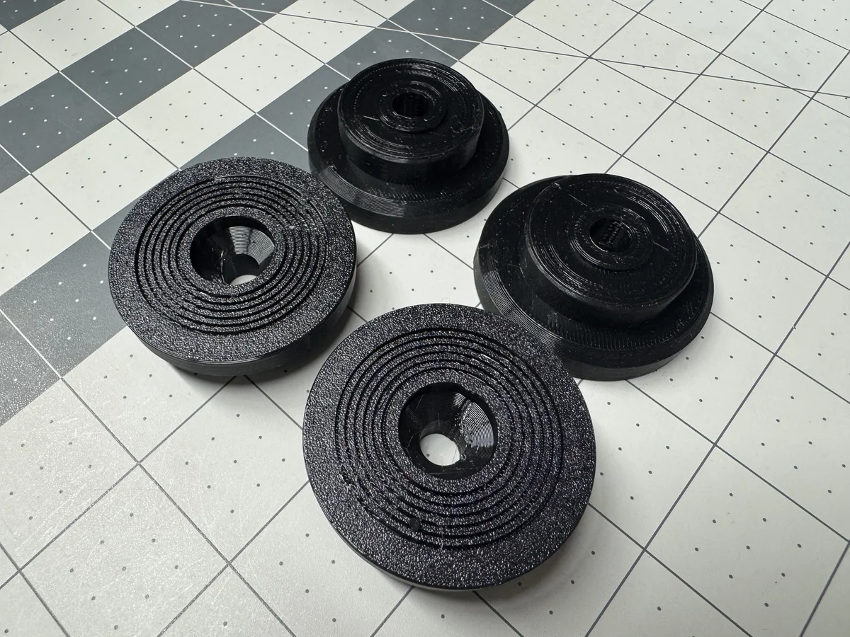
3. Travel cases and reconstructing lost shapes (1927–1960s)
Portable typewriters often attach compact circular feet directly to the bottom of their carrying case or baseboard with a screw and washer. Both the 1958 Hermes Media and the Princess 100 had originals squashed in creative ways, making them quick, rewarding replacements to print:
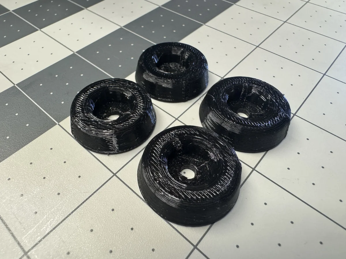
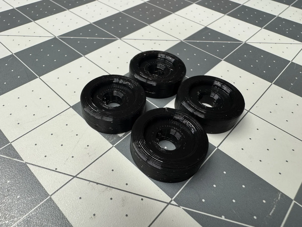
Not every portable leaves clear clues behind, though. Reconstructing the feet on my 1927 Varityper Folding (closely related to the Hammond Folding) required some guesswork. Inside the case bottom were aged, slightly cupped felt pads, and the surviving rubber remnants had deformed into that cup - yet if the machine was ever meant to sit directly on a table outside its case, the bottom of the feet had to be flat. Online photos of surviving Varityper and Hammond Folding machines weren’t much help either, as nearly all of them have badly deteriorated feet. I settled on a flat-bottomed design that wraps neatly around and inside the metal frame legs:
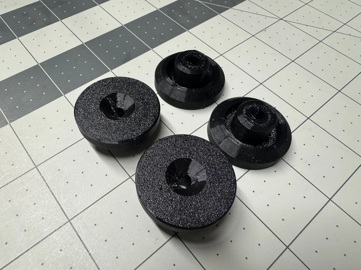
4. Beyond round feet: lofts, splines, and oversized blocks (1950s–1960s)
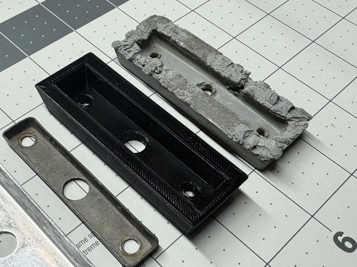
Mid-century European machines pushed me past simple revolved cylinders in Fusion. The 1951 Hermes Ambassador uses long, substantial rectangular feet sandwiched between stamped metal brackets. Modeling them was my excuse to learn Fusion’s Loft feature, combined with chamfers and fillets - and seeing the crumbling grey original next to the fresh black TPU part speaks for itself:
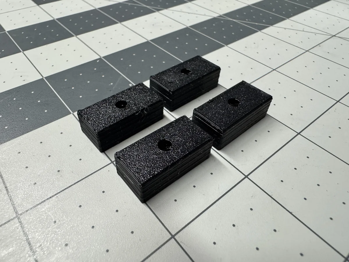
The 1960s Facit TP2 uses a very similar rectangular, metal-plate-retained concept at a fraction of the Ambassador’s size:
More challenging still was the 1960 Erika 10, whose elongated, boat-like feet are neither circular nor rectangular. Here I combined a loft with a flatbed scan of the original foot’s outline, tracing splines over the scan to approximate the curve. It isn’t mathematically exact - then again, neither were the factory originals!
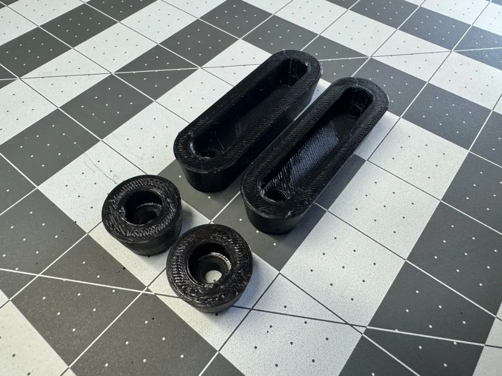
Finally, two 1950s office standards in my collection seat distinct front and rear shapes inside metal cups. The Olivetti Lexicon 80 pairs round conical front feet with elongated, two-screw rear feet whose deep inner pockets accept a metal retaining bar:
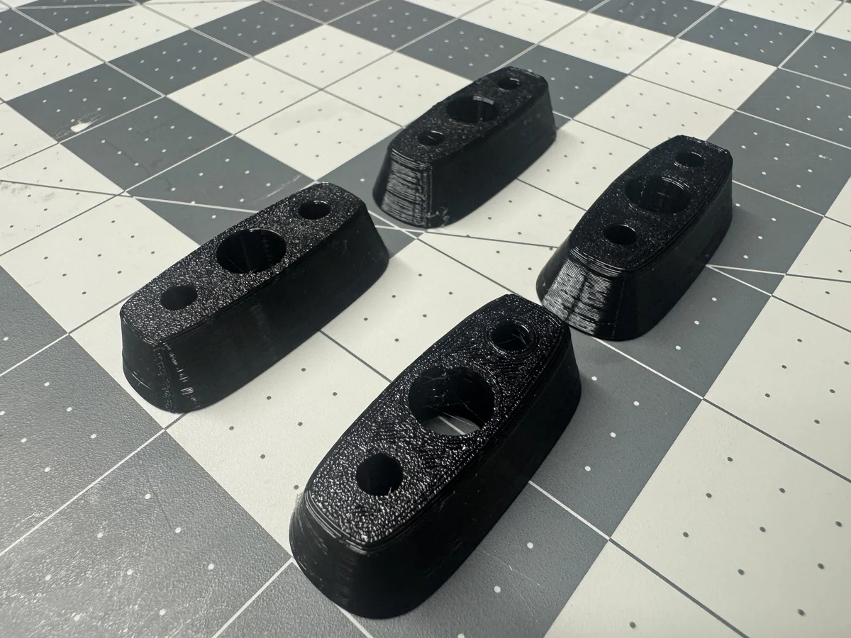
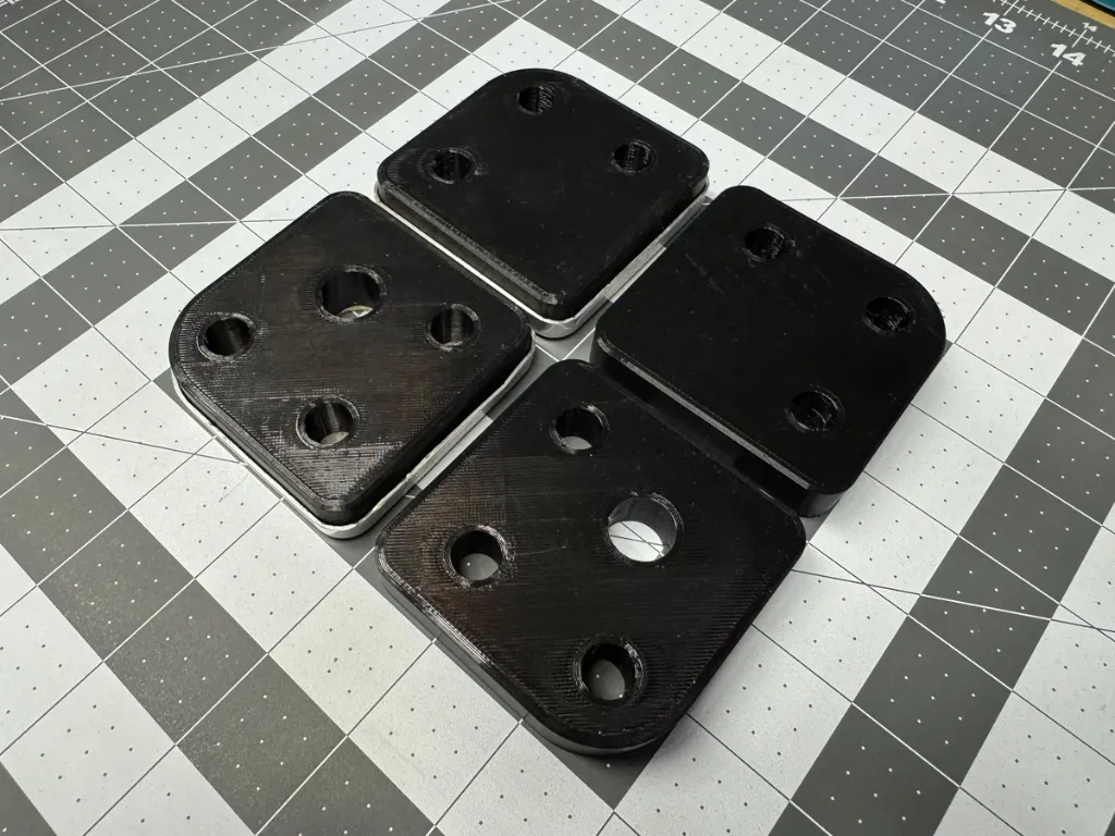
And at the largest end of the scale, my Adler Standard pads are over two inches across - the widest feet I have printed so far. Here the front feet include a larger central hole to clear a mounting nut in addition to the mounting screws, while the rear feet feature an opening at the back. On future revisions I might add a tread profile underneath so that broad flat contact area stays as grippy as possible:
Complete catalog on Printables
All of the models below are available on my Printables profile under a Creative Commons Attribution-ShareAlike (CC BY-SA 4.0) license. Because .stl meshes alone are tedious to modify when another machine needs a slightly taller foot or a wider screw hole, every download includes the original Autodesk Fusion (.f3d) and .step CAD source files alongside .stl and .3mf print files.
| Typewriter | Link | Year(s) | Attachment & Notes |
|---|---|---|---|
| Remington 2 | Printables | 1885 | Push-in |
| Densmore 1b | Printables | 1894–1896 | Push-in |
| Densmore 4 | Printables | 1899 | Screw-mounted; cylindrical and conical versions |
| Royal “flatbed” 1 / 5 / 6 | Printables | 1906–1913 | Screw-in; shorter or taller variants |
| Remington Model 7 with Gorin tabulator | Printables | 1907 | Push-in; tall, reinforced with internal steel rod |
| Smith Premier 5 with Gorin tabulator | Printables | 1907 | Push-in; tall |
| Blickensderfer 5 | Printables | 1909 | Push-in with top wood-screw hole and rear clearance notch |
| Courier | Printables | 1917 | Push-in with side clearance notch (Austrian Oliver 3) |
| Underwood 5 | Printables | 1920 | Metal cup and screw; tall variant |
| Remington Vertical Adder Model 21 | Printables | 1920s | Metal cup and screw |
| Varityper / Hammond Folding | Printables | 1927 | Push-in; wraps inside and around the metal frame legs |
| Royal KHM | Printables | 1938 | Sandwiched with metal hardware + top rubber cushions |
| Underwood “S” | Printables | 1942 | Metal cup and screw; fits beneath felt-like top cushions |
| Underwood “SS” | Printables | 1948 | Metal cup and screw; wide, grooved support-free base |
| Underwood Rhythm Touch | Printables | 1949 | Metal cup, insert, washer, and screw; wide |
| Adler Standard | Printables | 1950s | Wide square-ish blocks in metal cups; distinct front and rear shapes |
| Olivetti Lexicon 80 | Printables | 1950s | Seated in metal cups; round front feet and oblong 2-screw rear feet |
| Hermes Ambassador (early) | Printables | 1951 | Large rectangular bar sandwiched between metal brackets |
| Hermes Media | Printables | 1958 | Compact; screw and washer into bottom case cups |
| Princess 100 | Printables | 1950s–1960s | Cylindrical; screwed to travel case |
| Erika 10 | Printables | 1960 | Metal cup and 2 screws; spline-lofted oblong shape |
| Facit TP2 | Printables | 1960s | Compact rectangular block with recessed metal retaining plate & screw |
Trade-offs and beyond feet
What I love most about this workflow is the speed of iteration: going from a crumbled remnant and a pair of calipers to a fitted TPU foot installed on a machine takes at most a few hours, often much less. Even better, because filament costs pennies per foot, I have been able to outfit unrestored project machines before putting them back on storage shelves - protecting both the shelves and the typewriters until their turn on the workbench comes.
There are, of course, a couple of honest trade-offs compared with poured rubber:
- Grip: Shore 85A TPU is slightly less tacky than fresh rubber, though under the weight of a typewriter I haven’t found sliding to be an issue in practice.
- Cosmetics: Printed TPU has a slight sheen and visible layer lines. Underneath a typewriter frame, feet rarely draw the eye, so this doesn’t bother me at all. For perfectionists, someone recently suggested lightly buffing TPU on a polishing wheel to knock down layer lines and leave a matte, rubbery finish; flexible SLA resins - or using 3D-printed positives to cast silicone molds for poured rubber - are also possibilities, though for my needs direct TPU prints are already more than good enough.
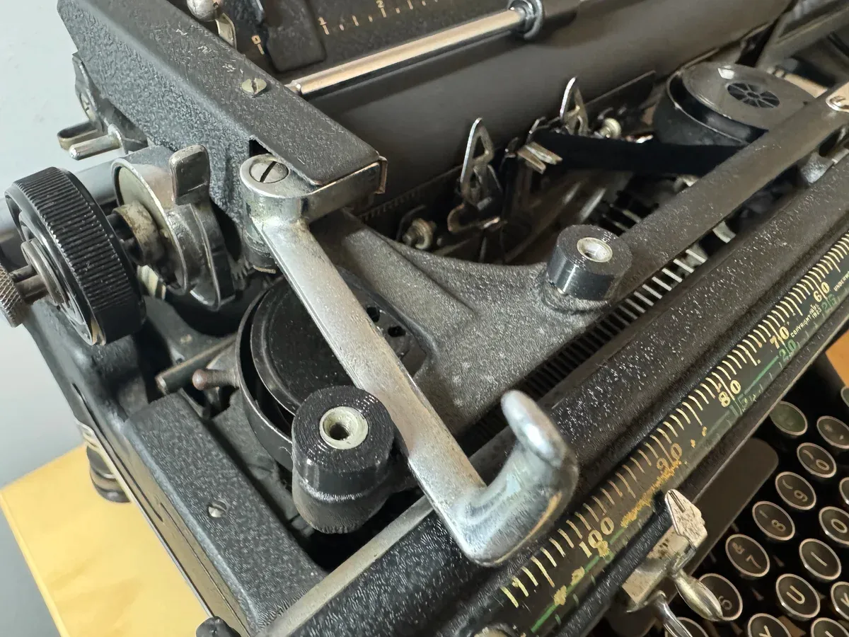
Once your printer is dialed in for Shore 85A TPU, other degraded rubber parts start jumping out at you too. For instance, I hadn’t realized how often carriage return lever bumpers split or flatten until I inspected my 1942 Underwood “S” and 1948 Underwood “SS” - each uses two tiny ring bumpers that take minutes to model and print (also on Printables):
Next on my curiosity list are paper bail and feed rollers (even though rubber tubing is an easy alternative), more foot designs as new machines cross the bench, and experimenting with even softer or variable-hardness foaming TPUs.
Comments powered by Disqus.