
Introduction
I previously wrote about my IBM Memory Typewriter and the first installment about its cleaning and restoration. In this post, I describe the continuation of the cleaning of the machine. This is still a work in progress as of October 2021.
The ribbon mechanism
The ribbon mechanism was very dirty and at first I couldn’t remove the ribbon cartridge.
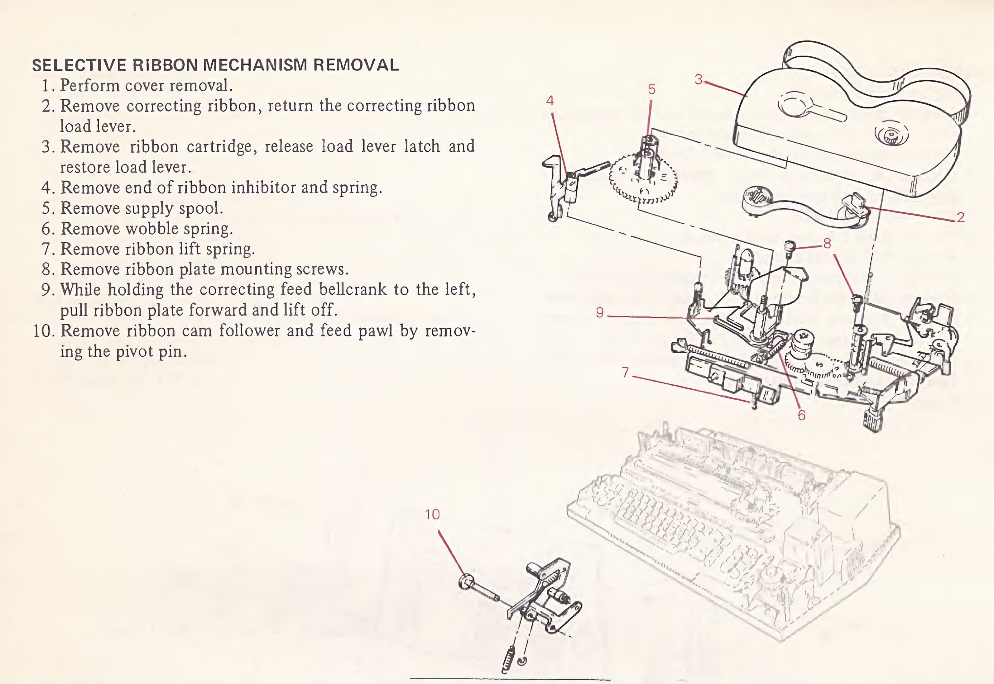
Luckily the service manual has detailed instruction about the ribbon mechansim and how things fit together.
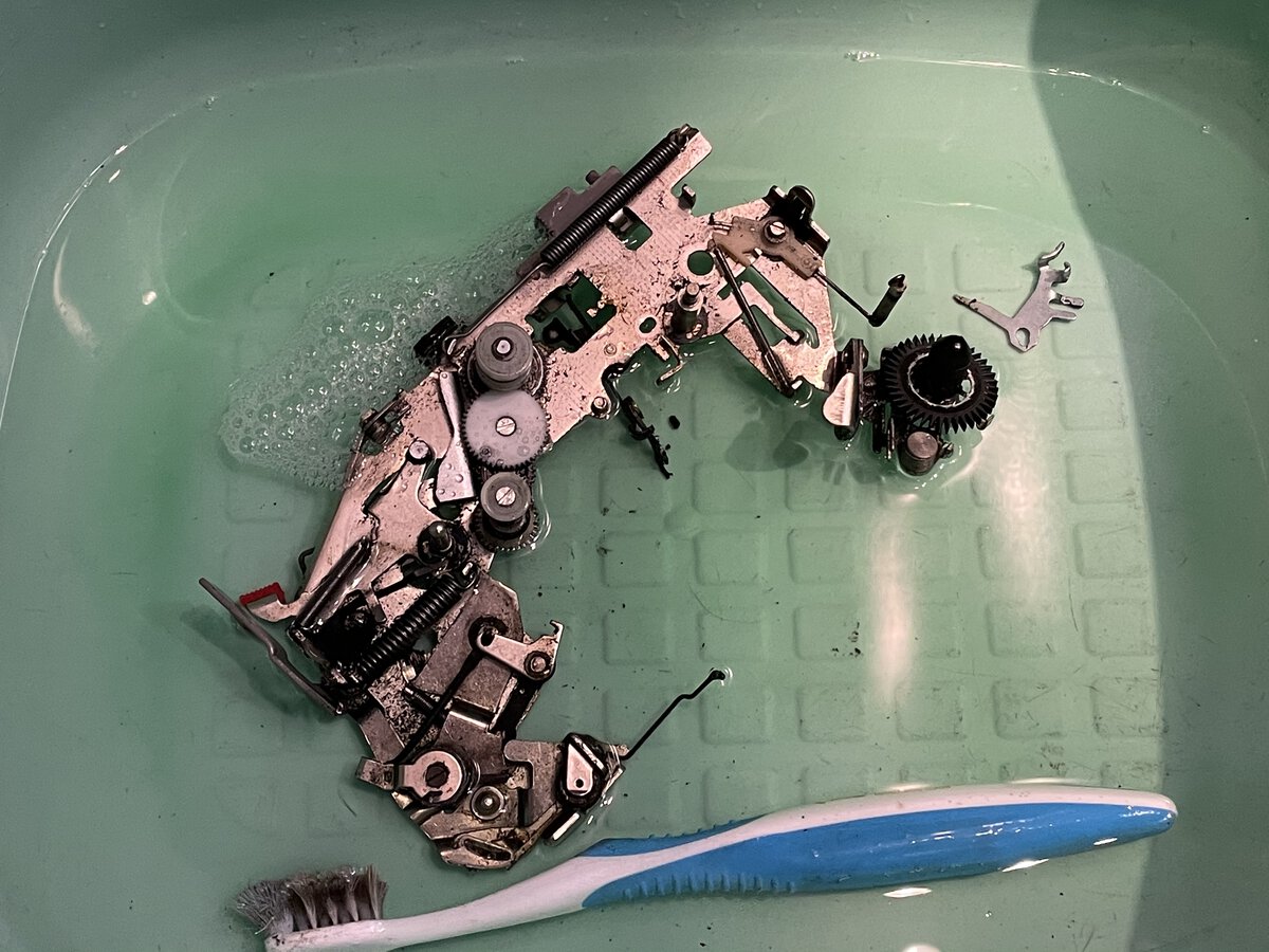
Still, I had to pull out the cartridge in an unorthodox way! It turned out that the swing arm on the ribbon mechanism was the part causing problems. It was completely stuck. I decided to take everything apart for in-depth cleaning.
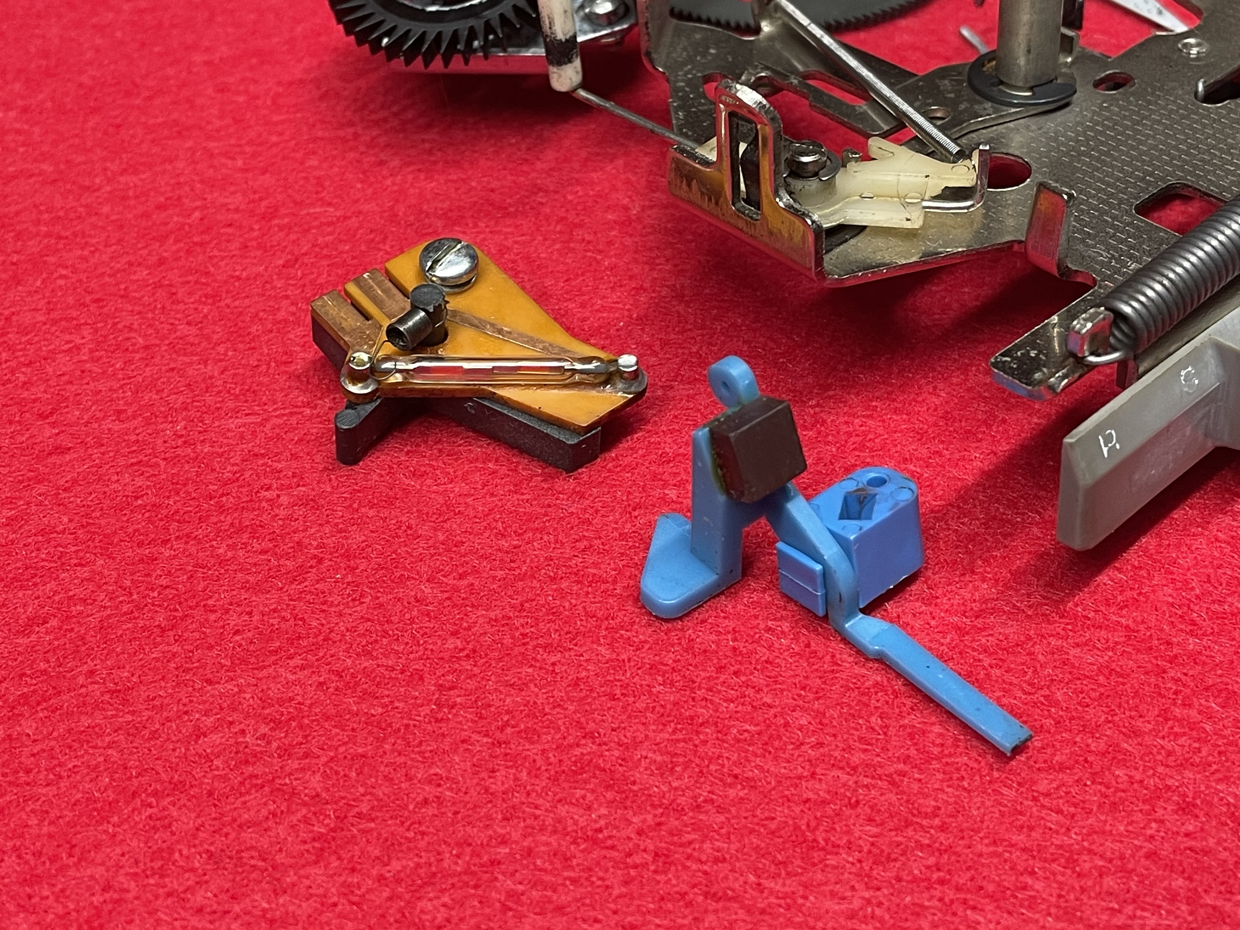
The parts came out really clean.
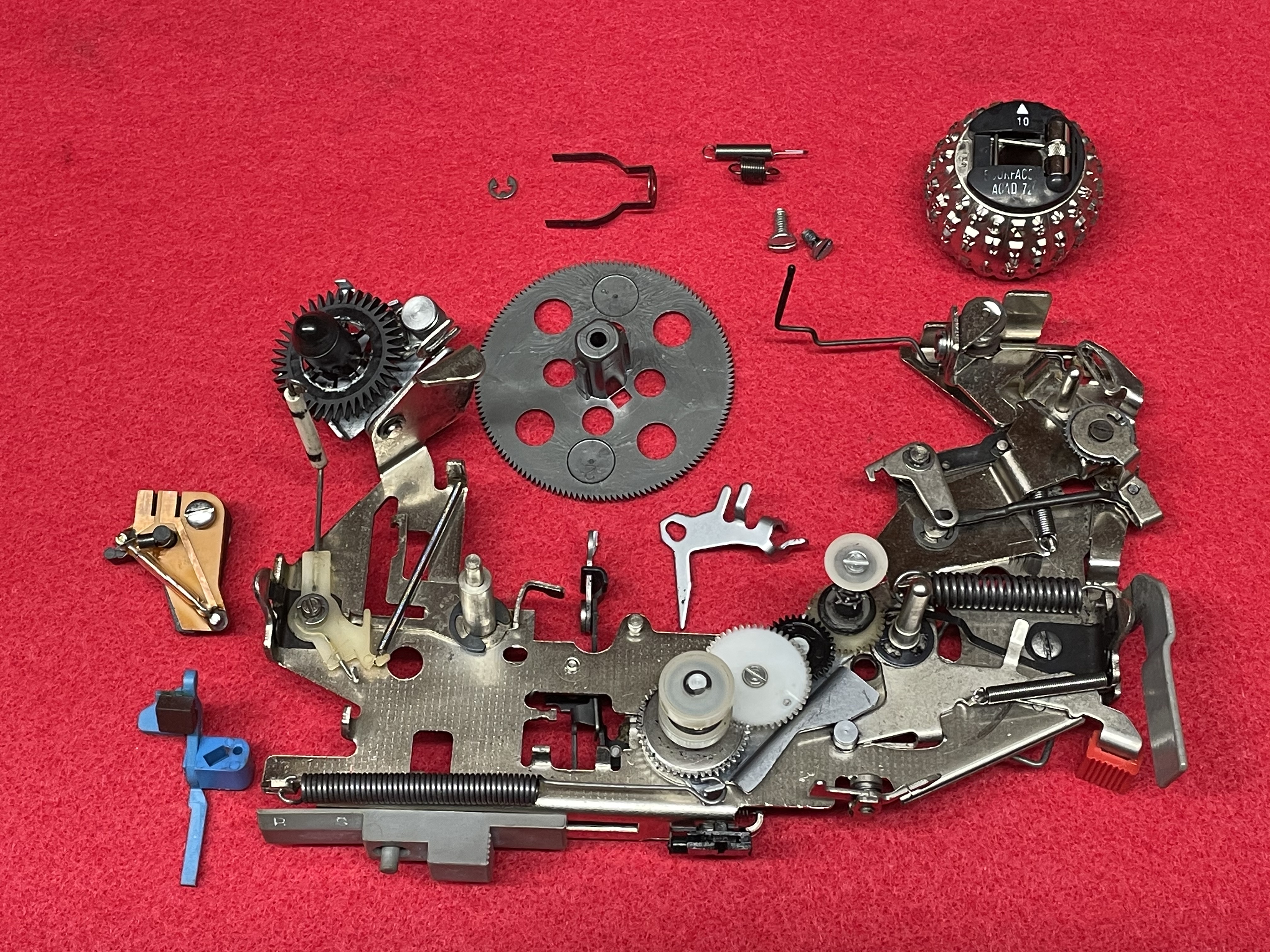
Unlike the regular Selectric, this ribbon mechanism also has a a reed switch and magnet to detect the end of the ribbon! Here is what the manual says:
The end of ribbon feature stops playout prior to the end of the ribbon. When the machine stops, the operator has the option of changing the ribbon at that time or resuming playout one line at a time until the copy is complete or the end of the ribbon is reached. When the end of ribbon mechanism is active, the machine will stop each time a carrier return is read.
The end of ribbon mechanism incorporates a sensor which senses the amount of ribbon remaining on the supply spool inside the ribbon cartridge. Tue sensor operates through a slot in the bottom of the ribbon cartridge and is held down (inactive) by the unused ribbon on the supply spool. When the diameter of the ribbon on the supply spool falls below a certain point, the sensor will snap up into its active position. In this position, the lower extension of the sensor, which has a magnet attached to it, will rotate against a reed switch circuit board, causing the switch to close. With the switch closed, the machine will operate in the LINE mode and will stop whenever a carrier return code is read from the card.
At first I thought that this was over-engineered, but in fact this makes sense for a machine that is able to print an entire page out of memory.
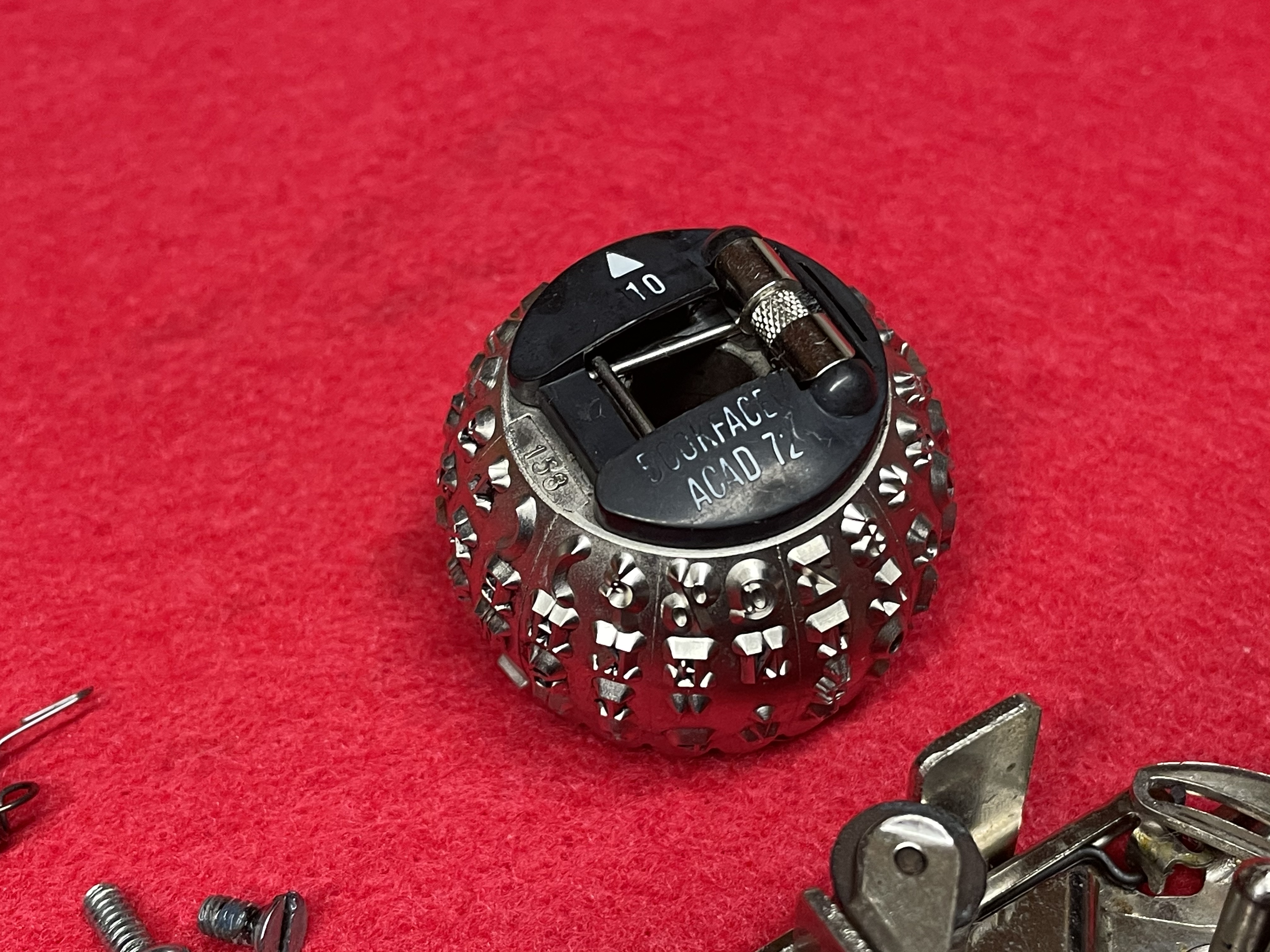
The type element had a broken tab, which is 100% certain to happen on elements with the metal hinge. I got it out following instructions in this video.
I found the broken tab inside the carrier! Not that it helps, because you can’t really glue it back.
More covers
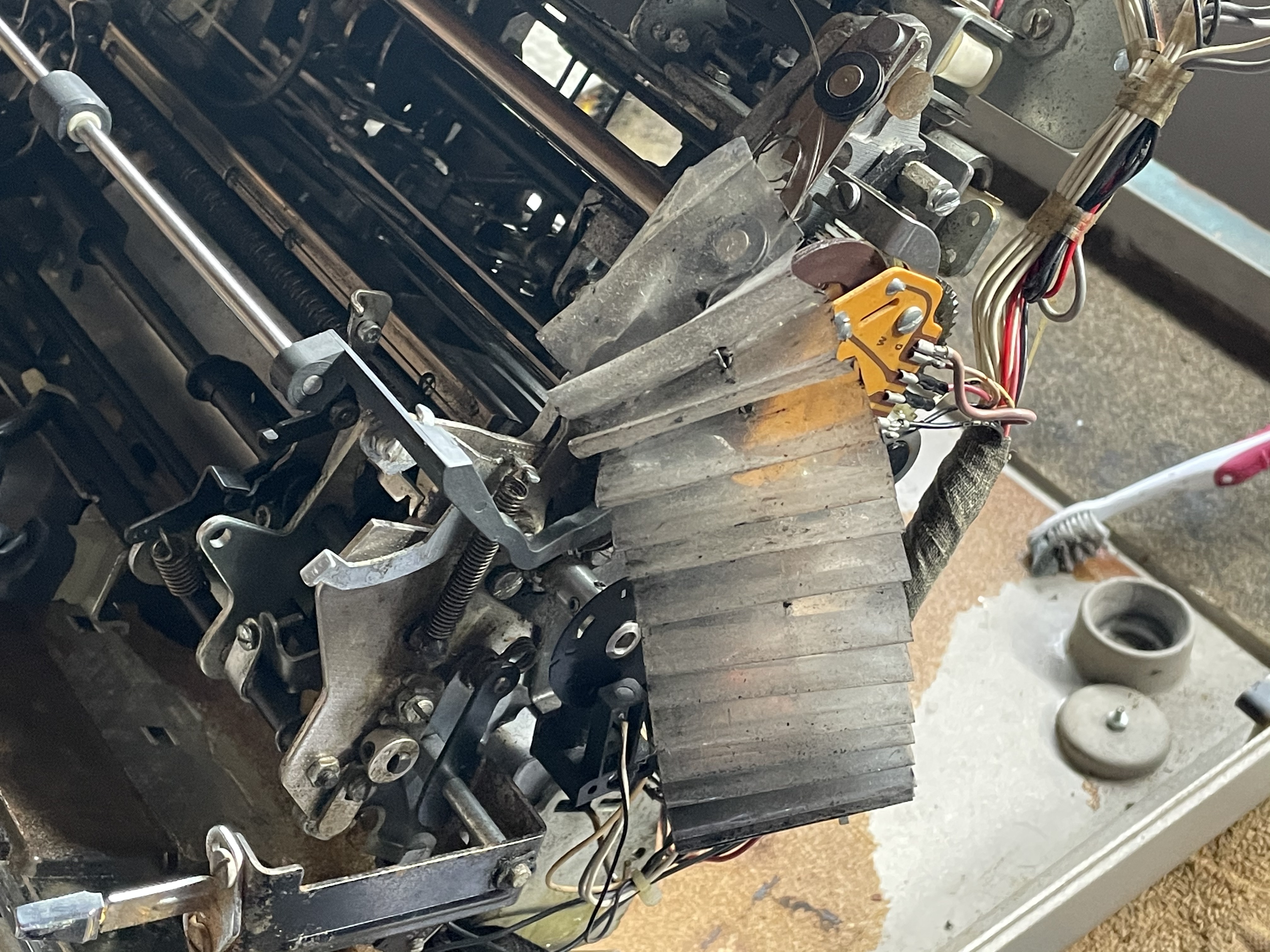
Below the ribbon mechanism, things were pretty scary.
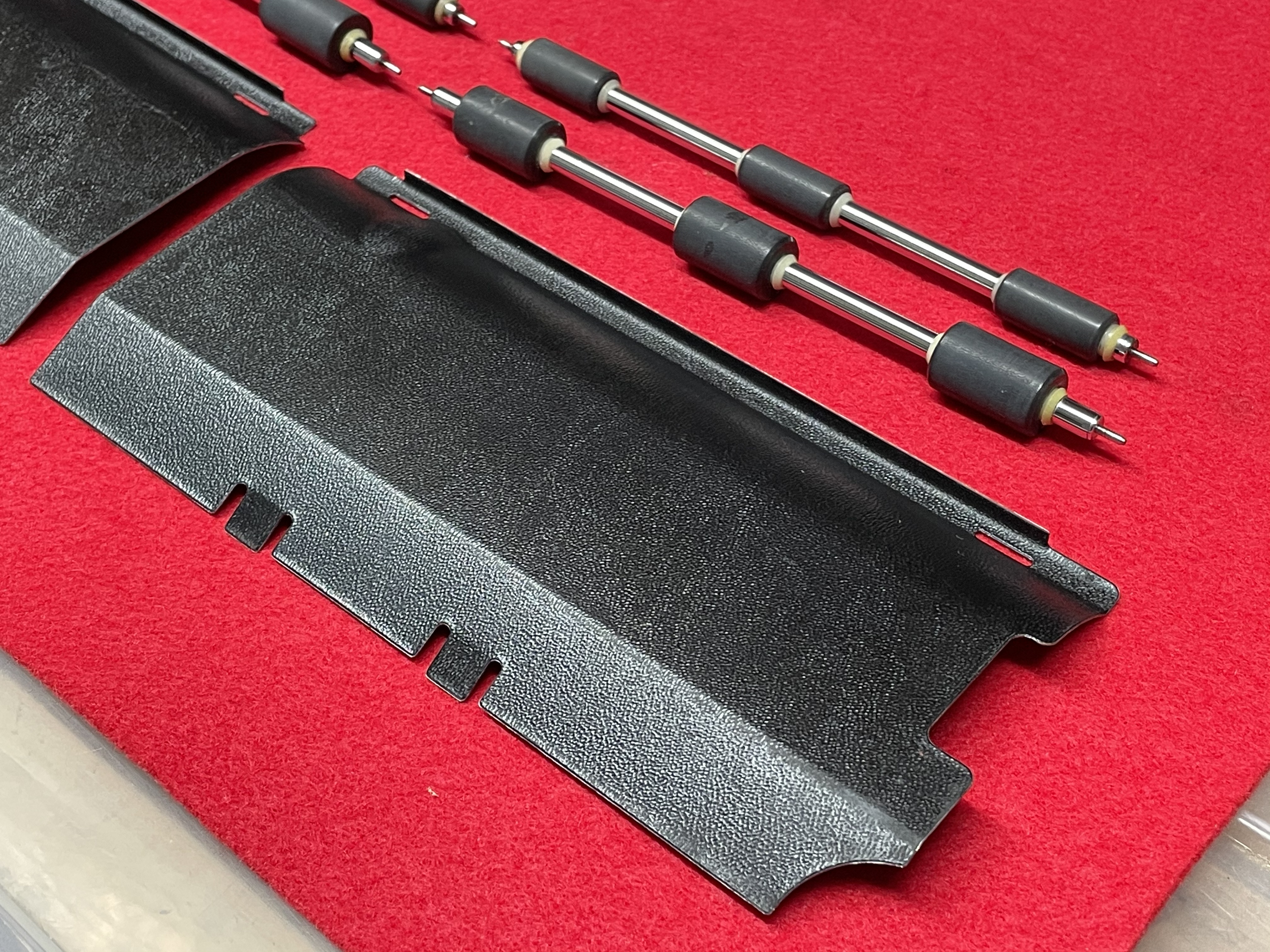
There is a plastic accordion “print shaft cover” which I detached.
This part required cleaning. But I don’t know how good it’s going to look in the end. I might have to consider replacing it.
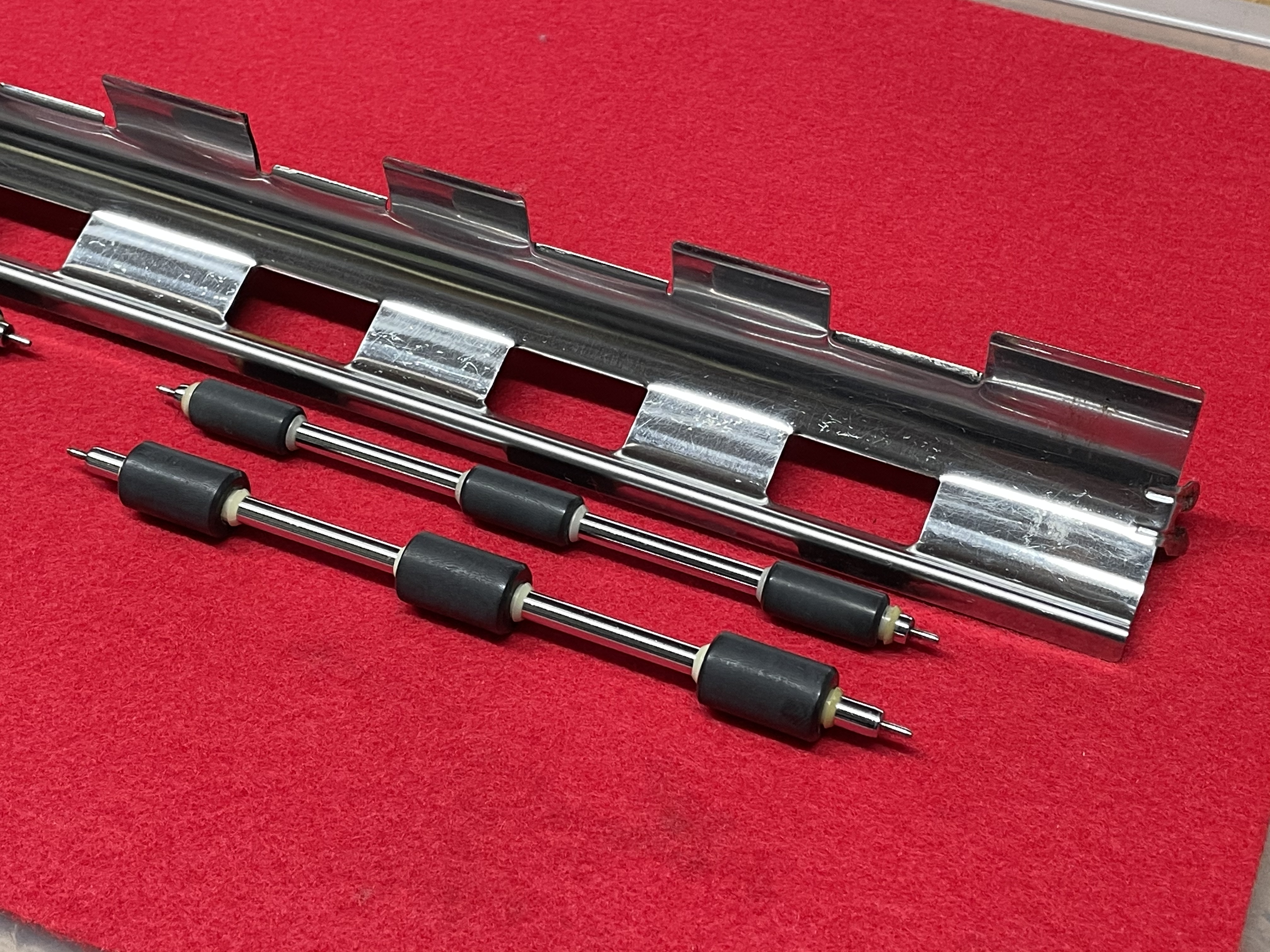
Underneath, there are actual print shaft covers. Those are metal, unlike the plastic ones of some Selectrics! I removed those easily and cleaned them.
The paper pan and feed rollers also got the same treatment.
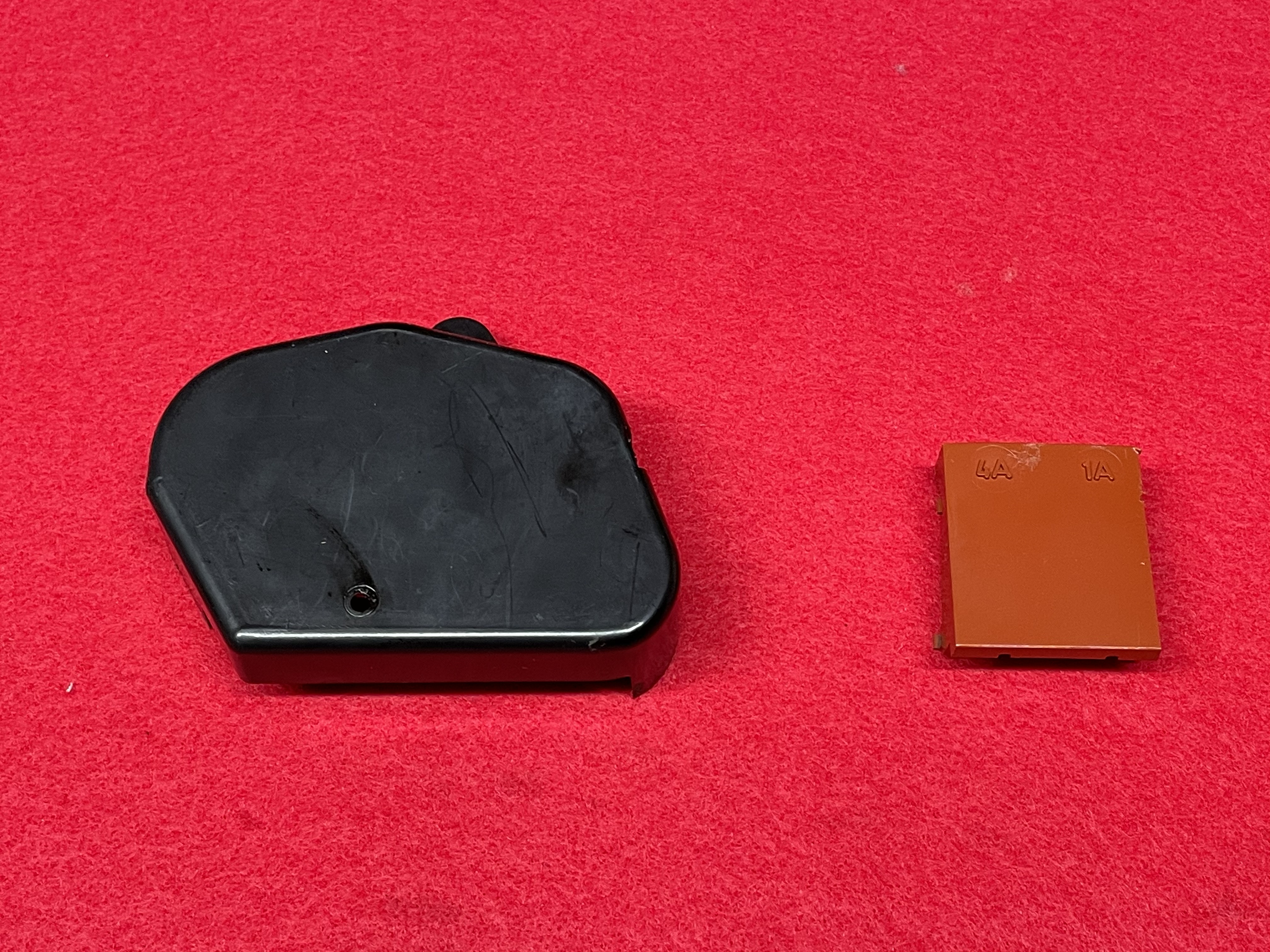
I removed two more covers, including one for the fuses.
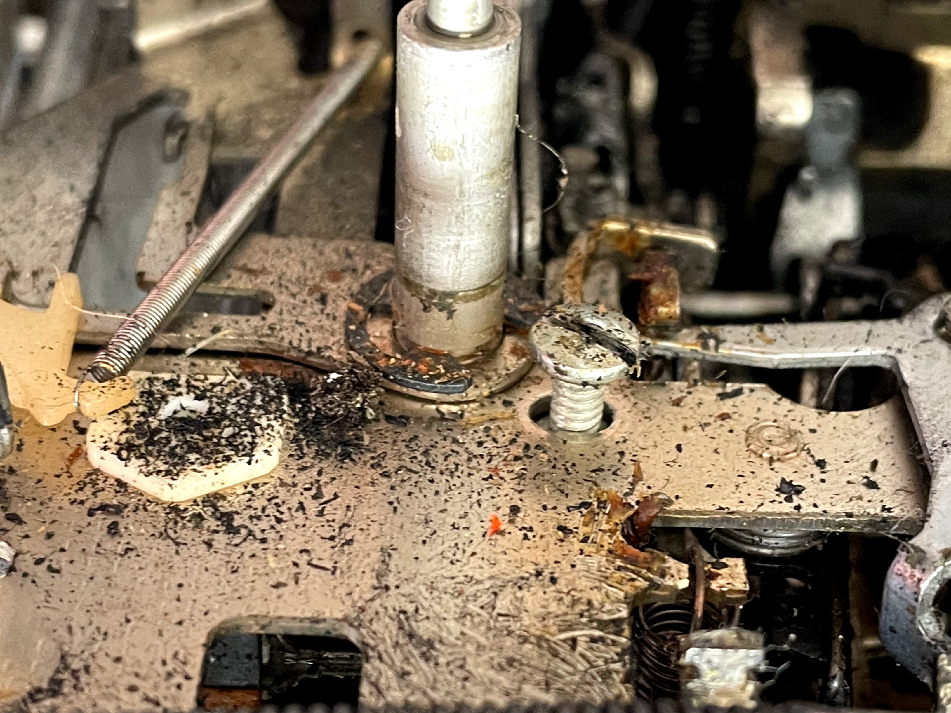
Cleaning the mechanical parts
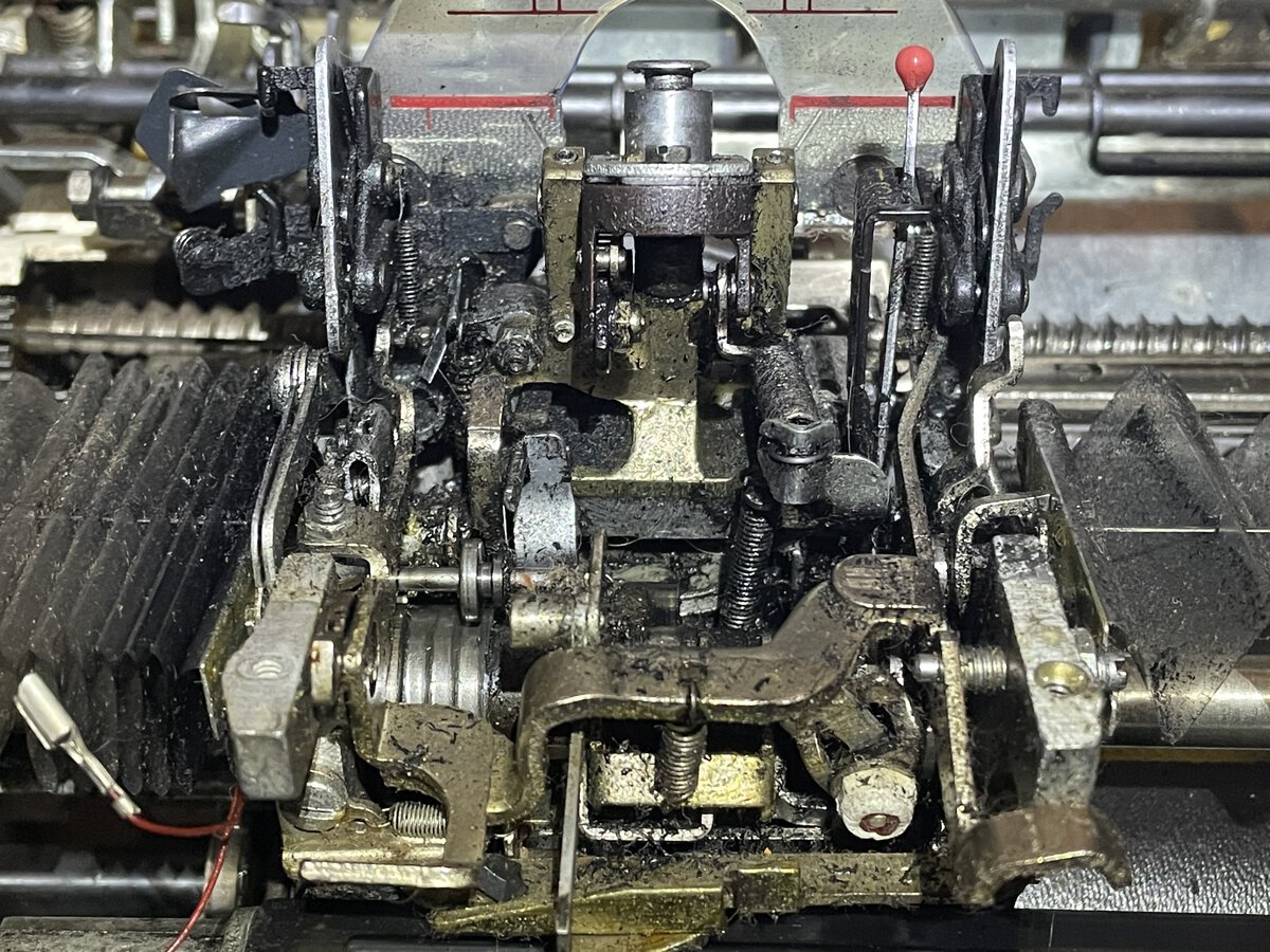
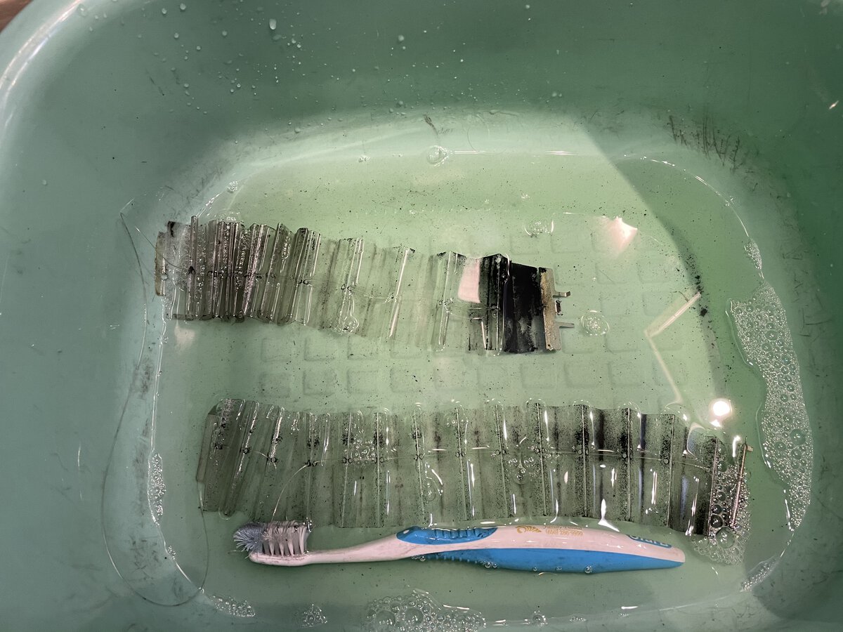
I wondered whether I should disassemble more of the machine to clean it. I was advised to clean things in place. I put rags to absorb liquids just in case, as I really don’t want liquids to reach the planar, and I used mineral spirits and a toothbrush to loosen grime and grease. I used compressed air to get the stuff out. It’s a slow and tiresome process, which I did with a headlight to see what I was doing. Here is an example of what I have to deal with.
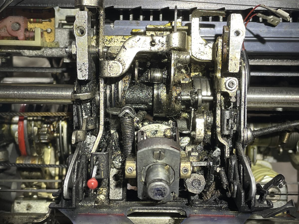
Halfway through the process, I tried the machine again. Things on the carrier appear to move much better.
Cable bundles
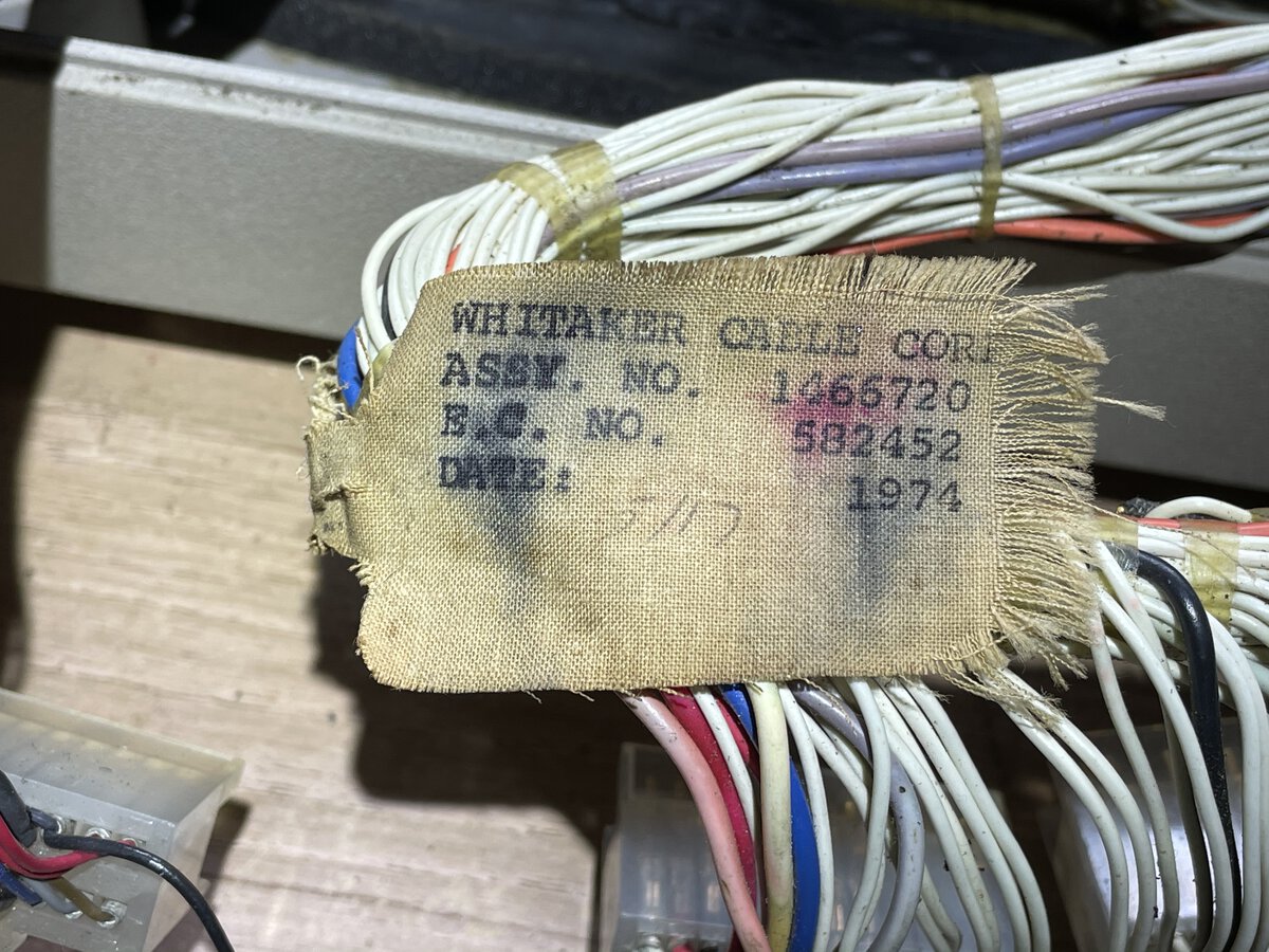
I note some markings on cloth labels attached to cable bundles. First label:
1
2
3
4
WHITEAKER CABLE CORP.
ASSY. NO.   1466720
E.C. NO.     582452
DATE:          1974
Second label:
The 582785 number could also be 582765.
1
2
3
4
WHITAKER CABLE CORP.
ASSY. NO.   1466002
E.C. NO.     582785
DATE:    7-11-1974
Third label:
1
2
3
4
WHITEAKER CABLE CORP.
ASSY. NO.    1466002
E.C. NO.      582699
DATE:           1974
For one thing, this confirms the 1974 date!
The planar and its support
I decided that I should remove and clean the planar even as I wasn’t done cleaning the rest of the machine.
- This provides better access for cleaning the machine.
- I wanted to make sure I didn’t damage it, for example by spraying solvents on it by accident.
- I wanted to clean it.
Removing it is very easy. It was designed to be removed and swapped if anything goes wrong with it. Remove the connectors, a couple of screws, and that’s it!
This clearly provides better access to the motor and other mechanical parts.
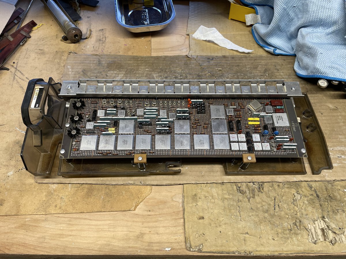
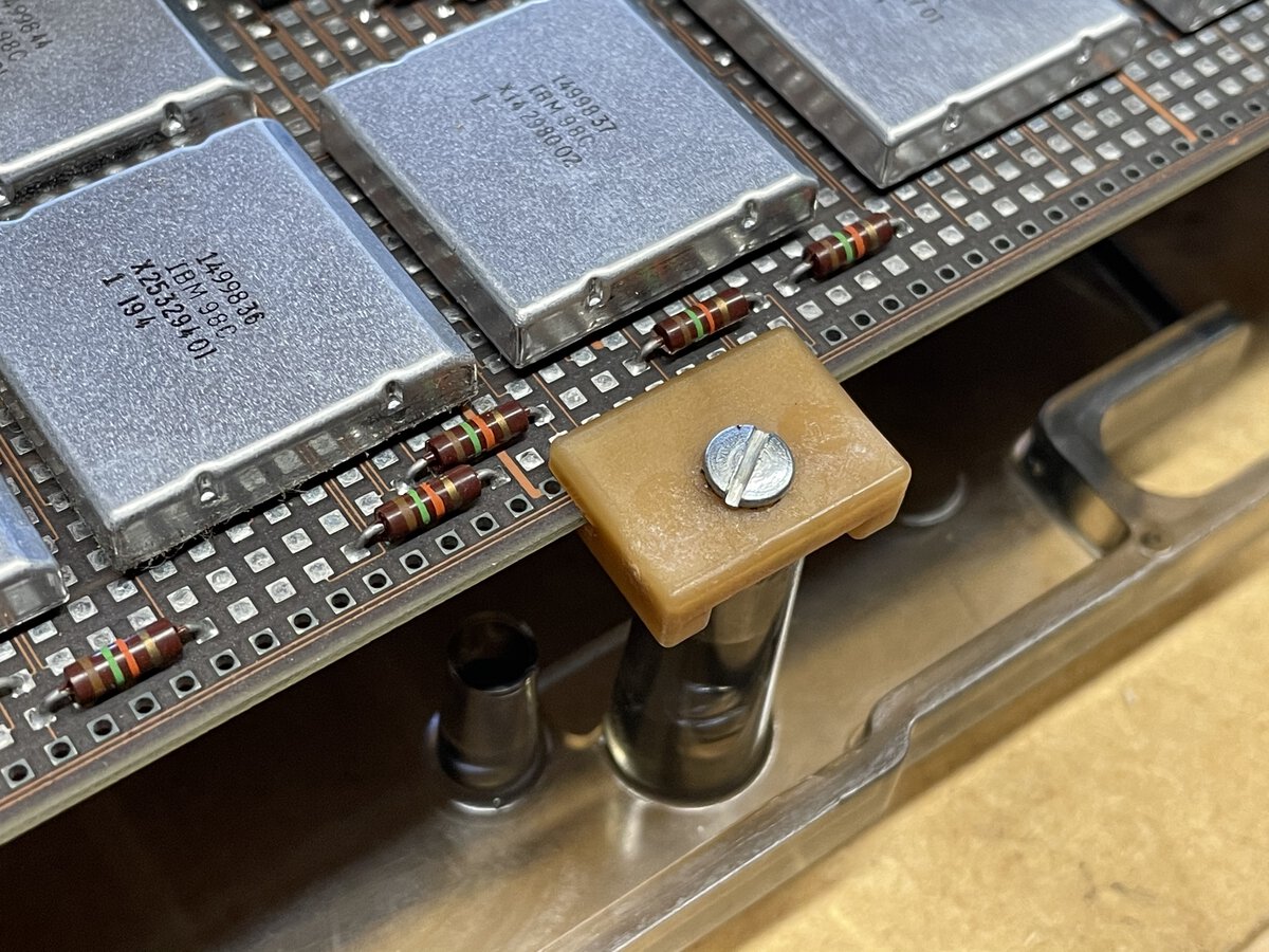
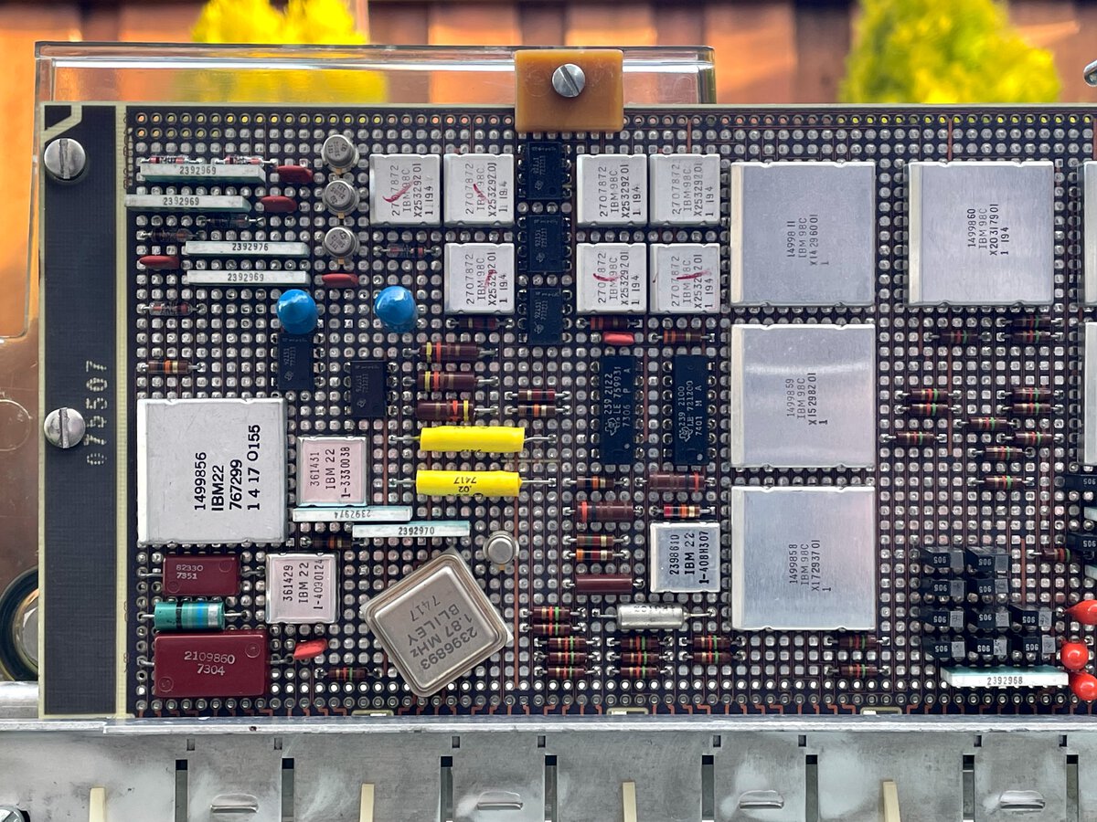
Now the planar is a thing of beauty. It is full of custom, unfortunately undocumented IBM chips. The planar would deserve its own post, but I’ll mention here that we identified the memory chips. It is pretty clear that these chips are shift-registers, and that each of those probably holds 4,000 (or maybe 4,096) bits of data. 7 chips provide 4,000 (or maybe 4,096) 7-bit characters or codes, which is the advertised memory capacity of the machine.
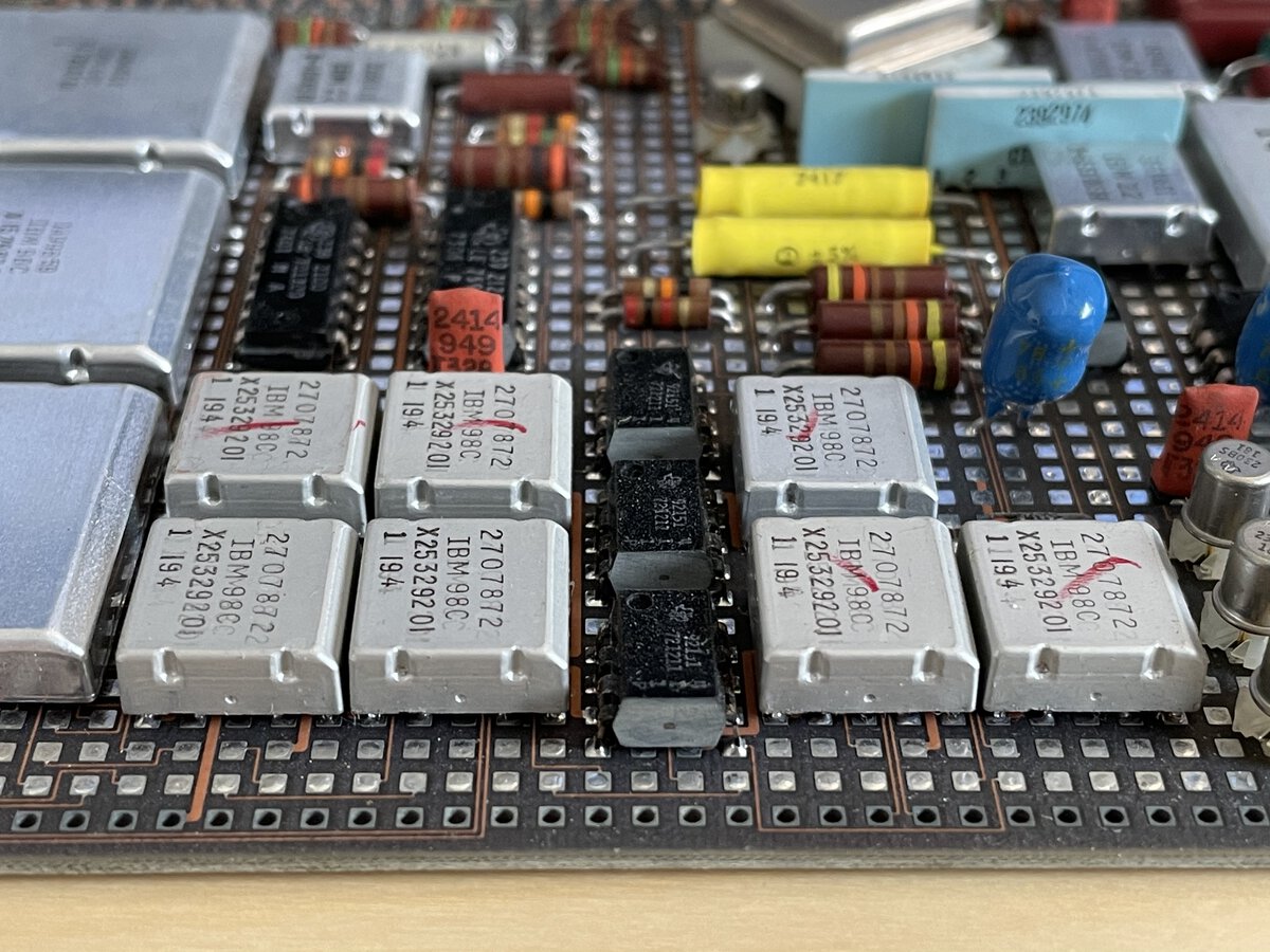
The memory chips are all labeled as follows:
1
2
3
4
2707872
IBM 98C
X25329201
1 I94
Note that the IBM Electronic Composer, a machine in the same lineage is the IBM Memory Typewriter, and which boasts 8000 characters of memory, happens to have 14 such chips.
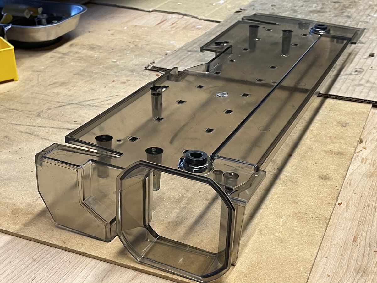
The planar is attached to a polycarbonate (maybe?) back. It had some soundproofing or insulation, which was all crumbling. I removed what I could, but it left a hard residue.
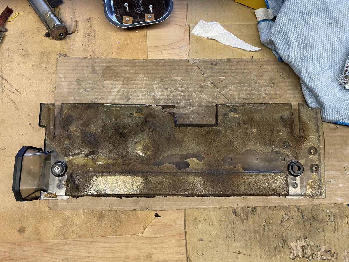
I removed the metal and plastic hardware.
Removing this residue was not easy. I didn’t want to damage the plastic. I tried various cleaners and solvents, including Simple Green and Goo Gone, which did nothing. In the end, I found that Hoppe’s #9 was slowly softening the residue. I could apply it, and, using a plastic blade, scrape it a little.
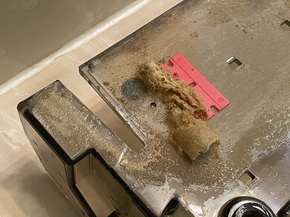
It took many passes over the course of one week to finally get all of it out. If you look closely and with the right light you will still see some scratches, but overall it’s a beautiful part!
The planar is attached to its support with brackets.
Note the air guide, which connects to the fan in the power supply, and which ensures that air reaches the planar.
The result is pretty neat.
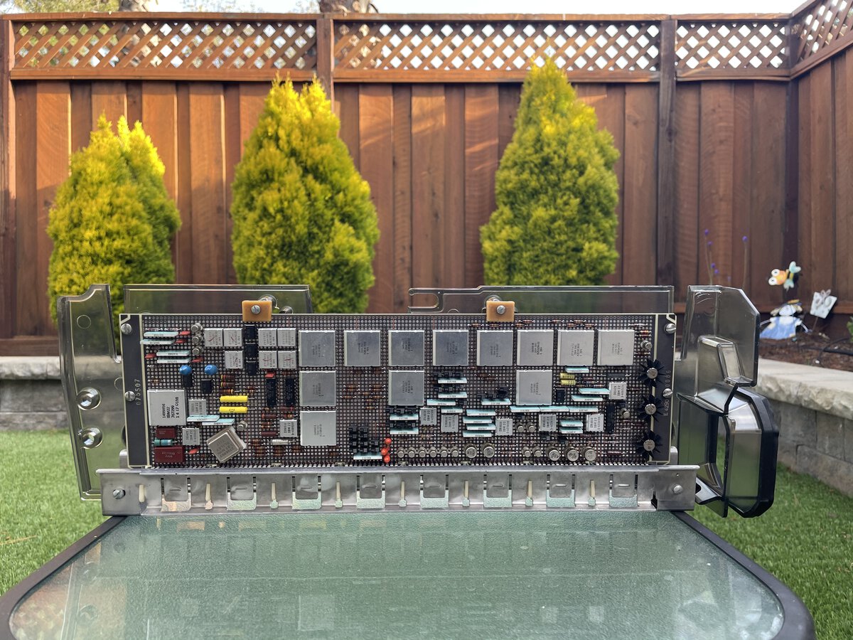
In the following picture you can see the memory chips at the top.
The planar bears several numbers:
- “E 4290 006” on one end of the planar
- “075507” on the other end of the planar
- “018524” on the air guide (sticker)
- “1466300 D” and “1466405” on the support (stickers)
I don’t know what they mean. Could some of the stickers be IBM service stickers?
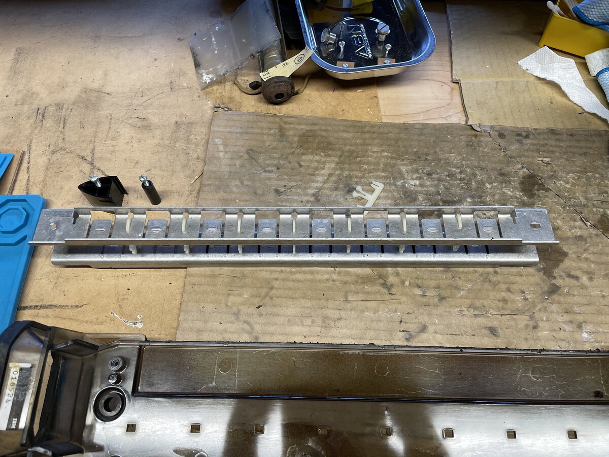
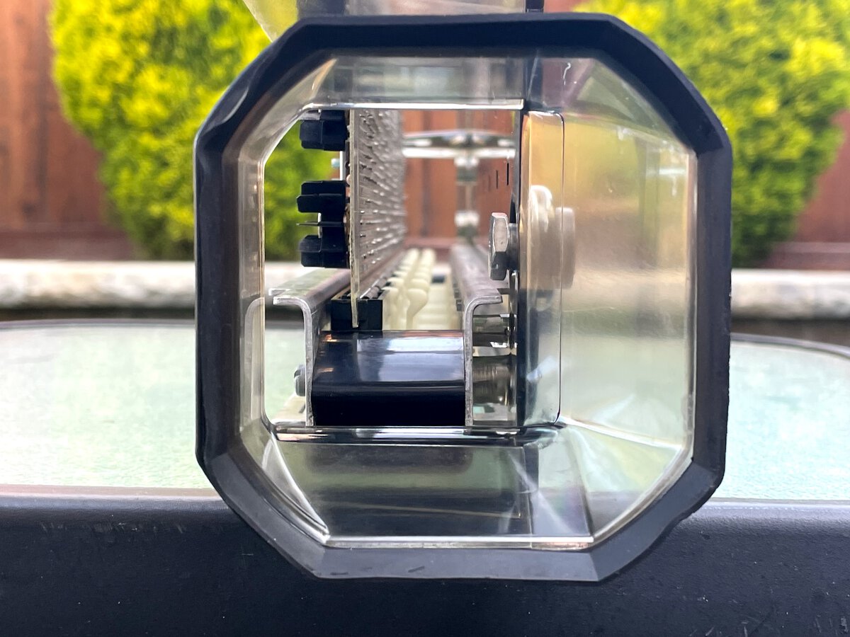
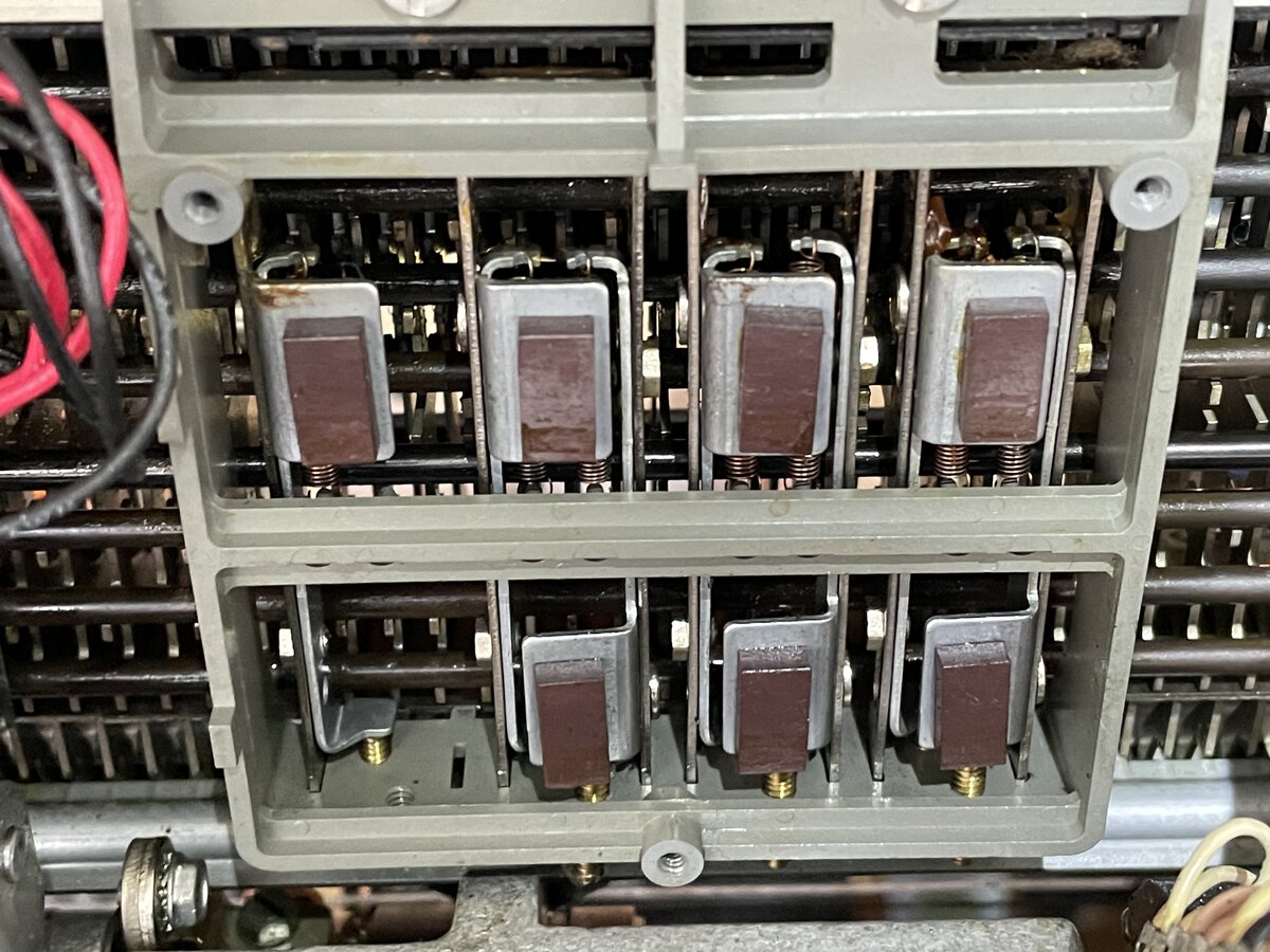
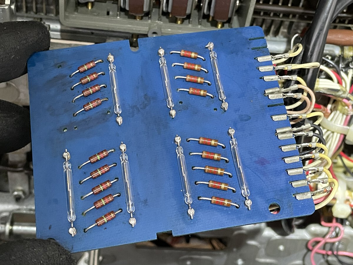
The transmit block
This is the part that “reads” the keyboard.
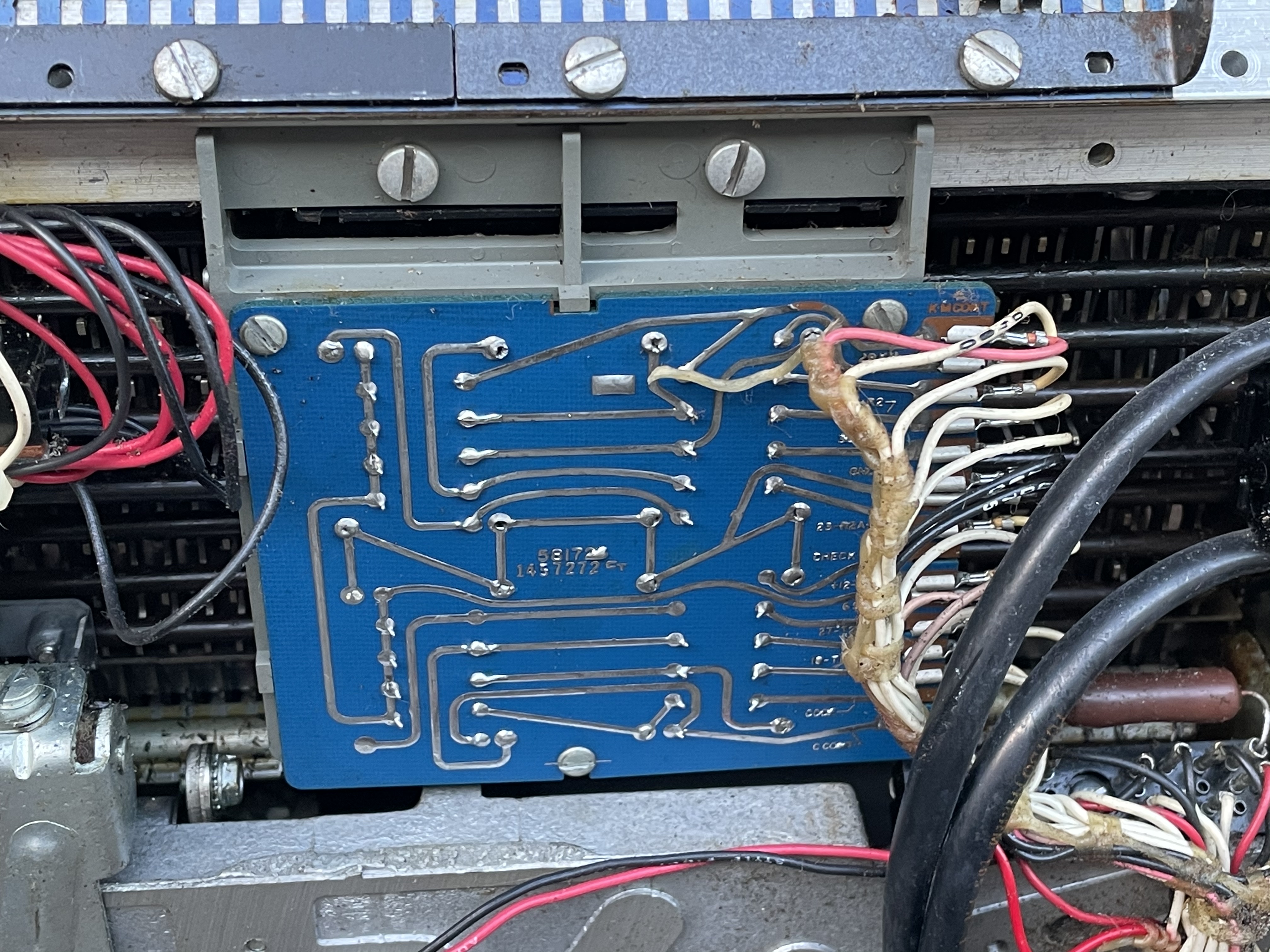
once you remove the PCB, you can see that it consists of seven magnets and seven reed switches. The magnets are activated mechanically.
The board with the reed switches was very dirty, no doubt in part due to my own cleaning of other parts of the machine.
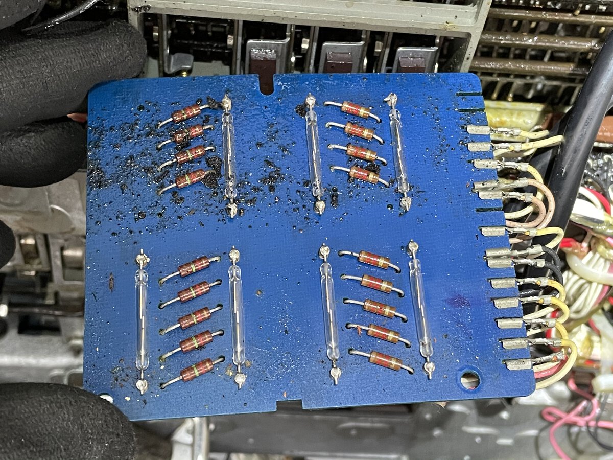
I cleaned it a little, but some black residues remain.
Conclusion so far
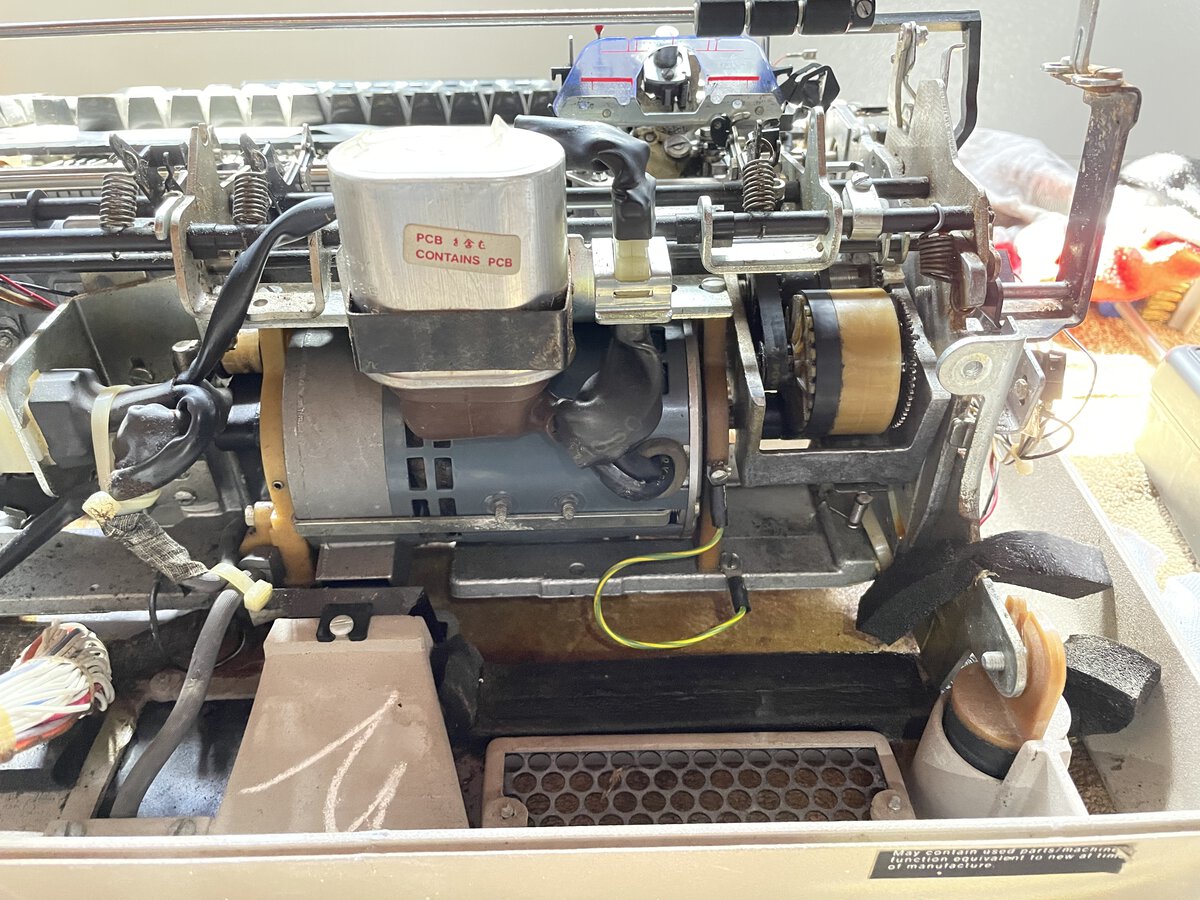
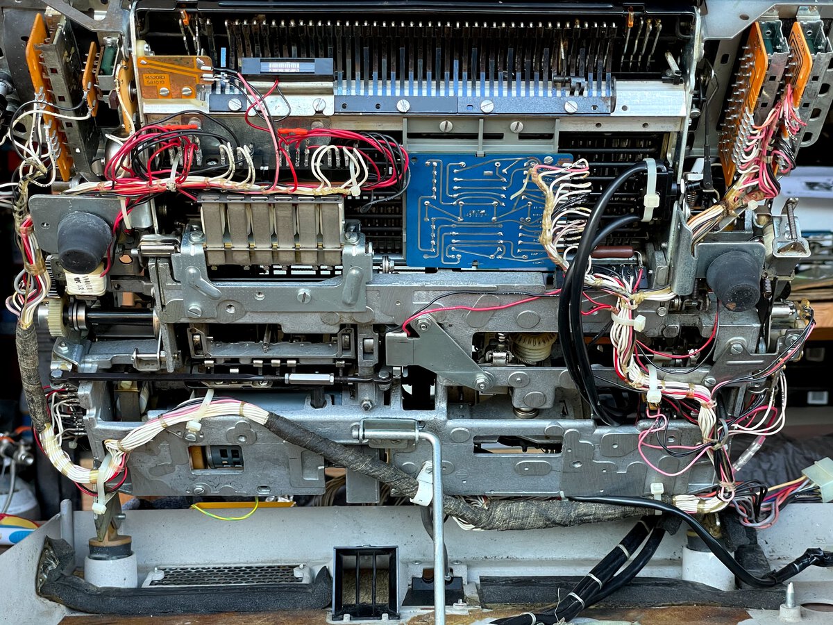
Here is a picture of the bottom of the machine as of September 2021, with the planar and power supply off.
I made a lot of progress, but I am not done yet. Here are tentative next steps:
- finish cleaning the mechanical parts
- apply grease appropriately
- reassemble and reinstall the ribbon mechanism
- reinstall the planar
- check the power supply
I mention the power supply because I took it out to take pictures, and I am now worried that if something went wrong with it, it could fry the planar. I am wondering what kind of crowbar system I could put in place to protect the planar in case something goes wrong.
Hopefully, with the ribbon mechanism and the rest of the machine cleaned, I will be able to test actually printing on paper!
More
- Blog post: The IBM Memory Typewriter
- Blog post: Restoring an IBM Memory Typewriter - Part 1
- Photo album: Pictures before restoration
- Photo album: All pictures of the restoration
Comments powered by Disqus.