
Introduction
In 2021, I wrote about my IBM Memory Typewriter project. See the following posts:
- The IBM Memory Typewriter
- Restoring an IBM Memory Typewriter - Part 1
- Restoring an IBM Memory Typewriter - Part 2
As of March 2024, I haven’t yet completed the Memory Typewriter project. However, in 2023 I bought an IBM Electronic Selectric Composer! And just because it was new-to-me and exciting, and because I am more comfortable dealing with these machines compared to when I first got the Memory Typewriter, I decided to start working on it.
The Electronic Selectric Composer is very similar to the Memory Typewriter. The following table illustrates how the machine fits into the lineup of IBM machines of the era:
| Machine | Memory | Separate Console | Storage | Announced | Proportional | System |
|---|---|---|---|---|---|---|
| Selectric | None | No | None | 1961 | No | ball |
| Mag Tape Selectric (MT/ST) | None | Yes | Tape | 1964 | No | ball |
| Selectric Composer | None | No | None | Sep 1966 | Yes | ball |
| Mag Tape Selectric Composer (MT/SC) | None1 | Yes | Tape | Sep 1966 | Yes | ball |
| Model D Executive | None | No | None | 1967 | Yes | typebar |
| Model D | None | No | None | 1967 | No | typebar |
| Mag Card (MC/ST) | None | Yes | Card | Oct 1969 | No | ball |
| Selectric II | None | No | None | Sep 1971 | No | ball |
| Mag Card Executive | None | Yes | Card | Apr 1972 | Yes | ball |
| Mag Card II | 8K | Yes | Card | Apr 1973 | No | ball |
| Memory Typewriter (MT) | 4K | No | Tape loop | Apr 1974 | No | ball |
| Electronic Selectric Composer (ESC) | 8K | No | None | Jan 1975 | Yes | ball |
| Mag Card/A | 6K | Yes | Card | Sep 1975 | No | ball |
| Mag Card Selectric Composer (MC/SC) | 8K | Yes | Card | 1977? | Yes | ball |
The main differences with the IBM Memory Typewriter are:
- more memory (8K vs 4K)
- no internal or external storage (no built-in tape loop, no external card drive)
- proportional spacing (or proportional “lettering”, as mentioned in a 1972 Mag Card Executive ad)
- ability to justify text
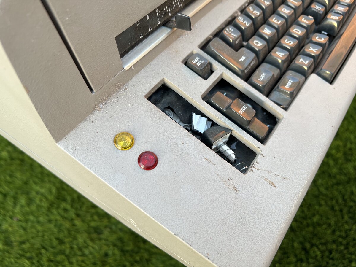
The last two features are, in fact, the whole point of the machine: the IBM Electronic Selectric Composer is, from the user’s point of view, an upgraded version of the IBM Selectric Composer from 1966, recognizable to its dials and justification indicator:2
Compare with the 1975 Electronic Composer, which looks more like a regular, although particularly wide, electric typewriter:
The earlier Composer was entirely electromechanical, and required the user to write each line twice to obtain justification. The newer machine, having an electronic memory, allows the user to write each line only once, and then to simply replay the page to justify text. Both machines feature proportional spacing.3
The market for the Composer (older and newer model) was that of cold typesetting. In fact these machines took a large part of the market from VariTyper.4
Shipping
I am grateful that the seller spent time packing the machine into a huge wooden box. The final package weighed 97 lbs, while the Electronic Composer itself weighs 59.2 lbs (26.8 kg)! However, the machine arrived with some damage: the three push switches on the left, as well as two toggle switches broke.
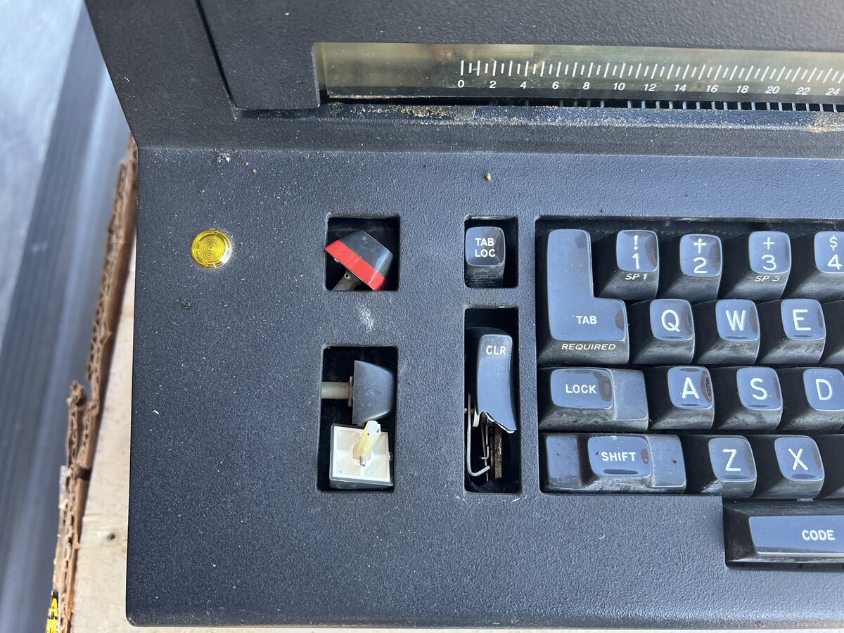
Seeing this worried me, of course. The machine was delivered to me upside down, and while that, in itself, doesn’t fully explain the problem, I suppose that these switches are fairly fragile. Indeed, they were broken also on my Memory Typewriter 100 (which I haven’t worked on at all yet). Another Electronic Composer I saw on Reddit had two broken switches as well.
The good news is that I took some detailed pictures and did a first round of evaluation of the machine, and I didn’t find any other obvious damage. Another good news is that insurance paid for some of the damage!
Dating
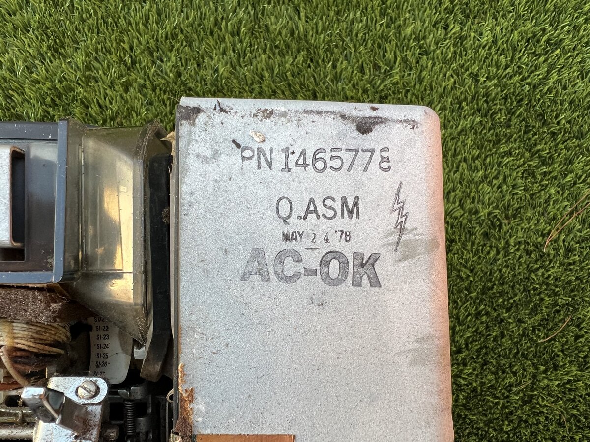
The first Electronic Selectric Composer came to the market in 1975. Although this machine has a couple of cable labels with the date 1975, the date on the power supply (PSU) states clearly “May 24 1978”. Unless that part was replaced, that probably sets the date of manufacturing of the machine to 1978. I also found a date of 1974 on the internal metal frame of the machine, but that is part of the metal casting. This part might be identical to the 1974 Memory Typewriter’s, and it could make sense that it was designed that year, but it doesn’t indicate a production date. So at this point I am going with 1978 as production date.
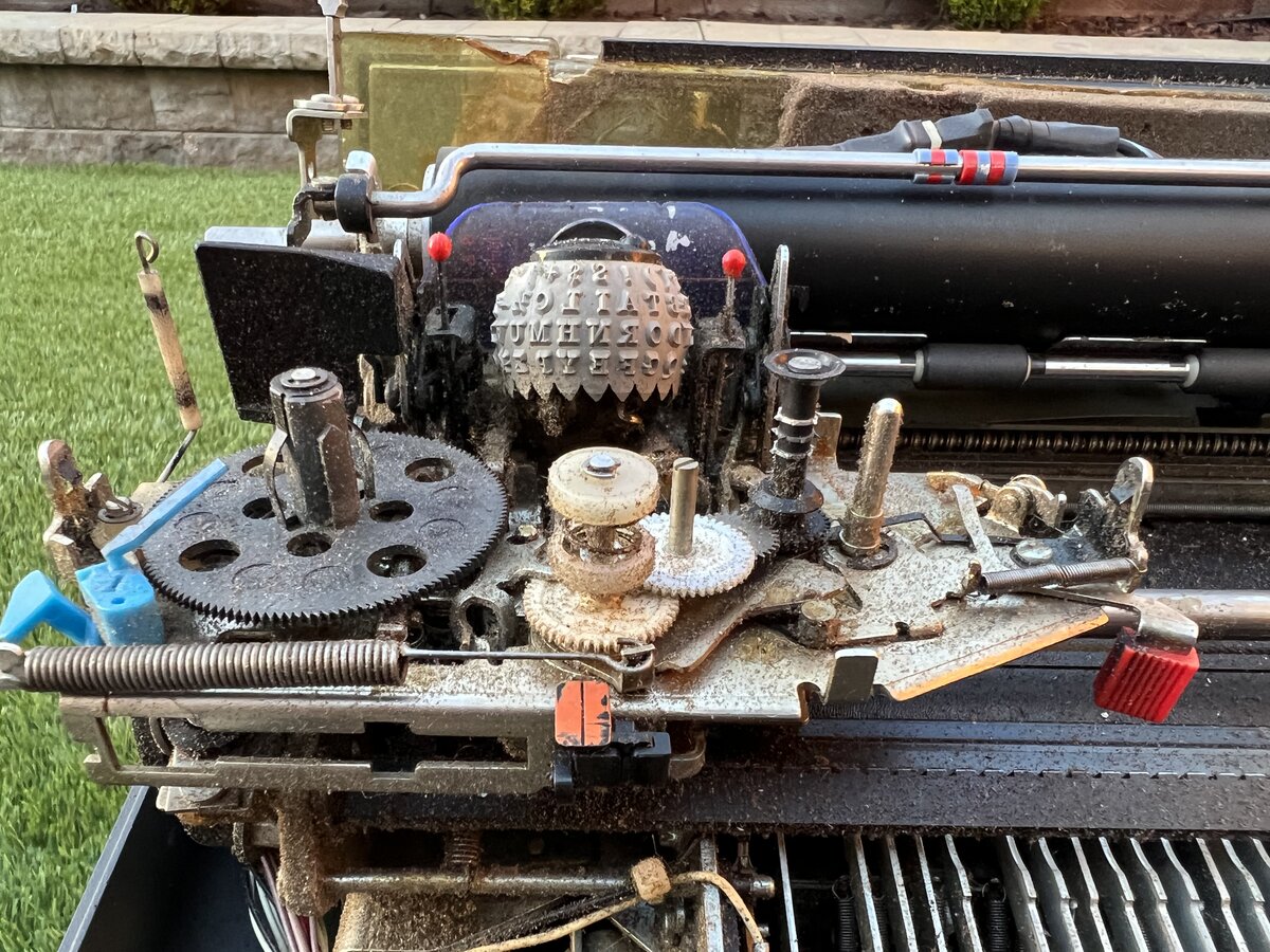
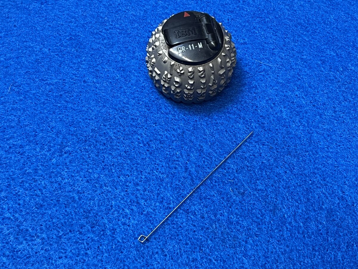
Type element
Unfortunately, this machine came only with one type element (“golf ball”). Those are not compatible with the regular Selectric type elements. However they are compatible with the original Composer elements. IBM had a whole catalog of type elements for the Composer. I’d love to find more of those, especially if the machine ends up working. 5
The element I have states “PR-11-M”.
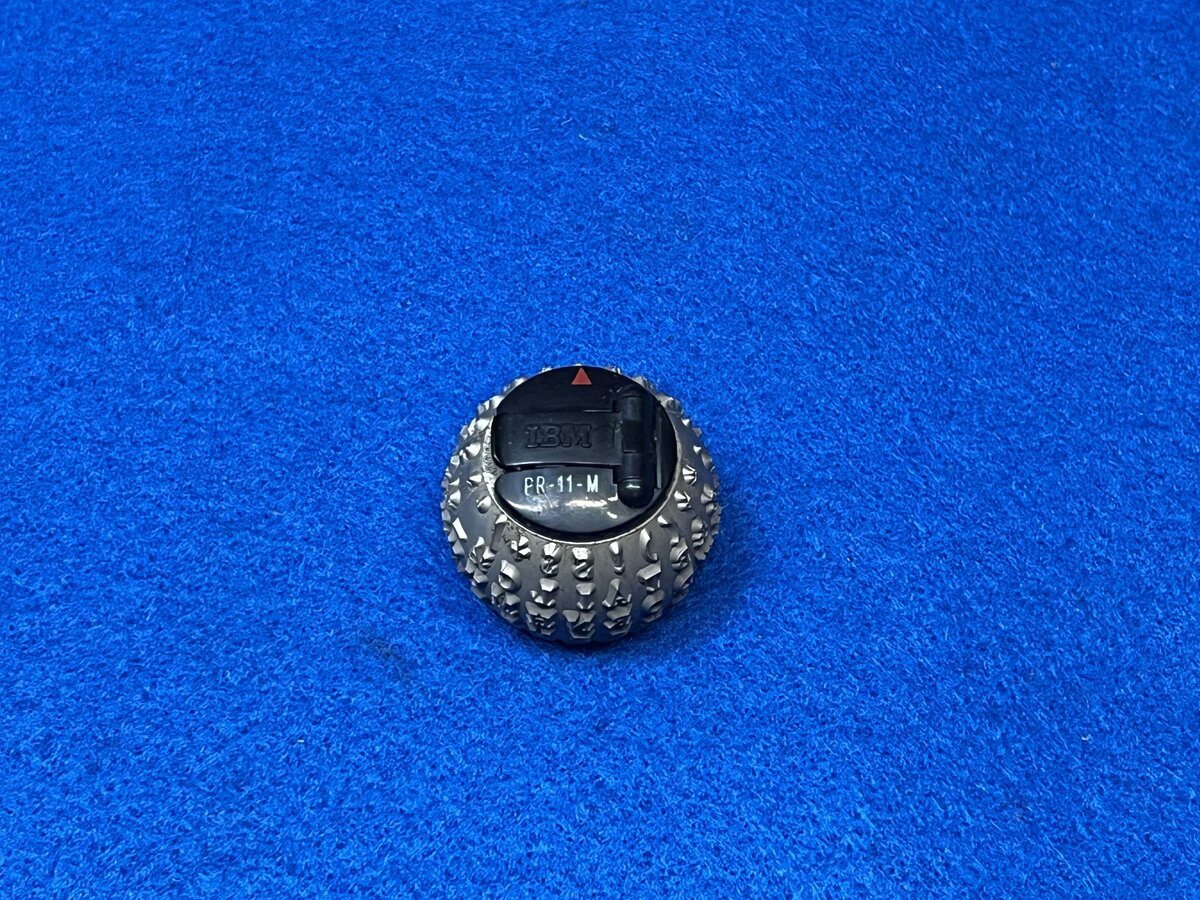
This is what it means:
| Text | Meaning |
|---|---|
| PR | Press Roman typeface |
| 11 | 11 point |
| M | Medium weight |
The red arrow generally means 11/12 pt size.
Initial rough cleaning
How does one get started on such a machine? The good news is that I already have some experience with two similar machines: the Memory Typewriter and the Mag Card/A.6 Neither of these machines work yet, but I have studied them and partly disassembled, cleaned, and started fixing them. I read parts of the service manuals, I know the general architecture of the machines, and I have a good idea of how they work. So I have some confidence about how to tackle them. This said, I am not a professional Selectric service person, very far from it, and if there are any issues with the Selectric parts proper, I have to ask for advice.
The first thing to do with those machines is to take lots of pictures. You want to document the condition of the machine was before you do anything to it (partly to make sure you didn’t break more stuff!). It’s hard to commit this kind of things to memory, and it’s so easy to take pictures nowadays!
The second thing to do is a general evaluation: is anything missing or broken? How much cleaning will be needed? Obviously machines can get dusty and dirty, and have all sort of things getting into them. But with these IBM machines specifically, there are two things to be aware of:
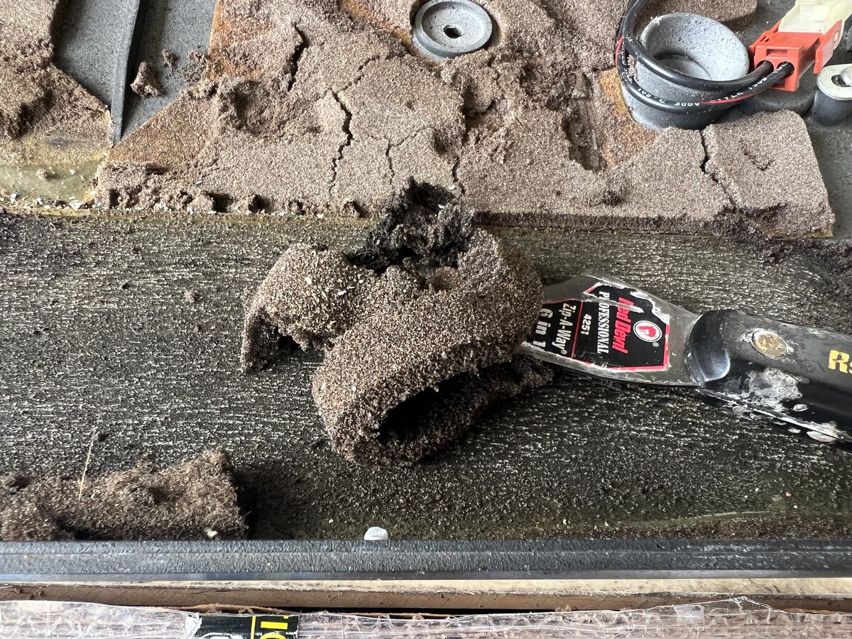
IBM put in sound deadening material that, in absolutely every single case, disintegrates in ways that are not very pleasant. It’s the lucky case if it disintegrates and remains dry, but in many cases, it’s a gooey stuff. So all of that needs to be removed first, so you can avoid dealing with it when you actually work on other aspects of the machine.
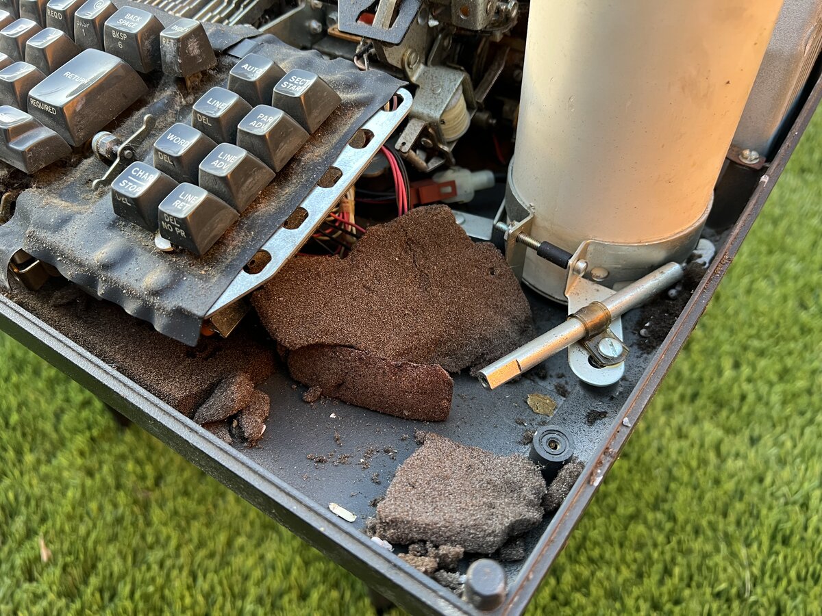
Crumbling foam Many typewriters don’t need much oil or grease, but Selectrics were lubricated with both. The problem with grease is that it can harden over time, and it will cause the machine to stop working. For this reason, many regular Selectrics don’t work when you find them.
You don’t want to just turn on an old dirty machine without thinking. It is wise to do some cleaning first, then turn it on for a short period of time to see if anything is moving.
In this case, after removing the top cover, I noticed that, as was the case for my Memory Typewriter, the two screws that hold the machine to its hinge on the left were missing. In this case, though, they were at the bottom of the case, and I was able to just screw them back. This is important so that the machine can be lifted on its stand.
Then I scraped the sound-deadening material, and I cleaned the machine with a vacuum cleaner and compressed air (making sure not to vacuum or blow away small parts).
This is not the end of it, however, with a lot of dirt remaining in the machine, a lot of it some of that disintegrated material.
While cleaning, I found a few loose parts:
- bits of the broken switches
- a magnet, which I established was part of the end of tape sensor
- a spring, whose original location I think I determined later
- a wire, which is the “No Print” lever wire (thanks experts online!)
After that, I disconnected the capacitor and the planar (electronics board).
I tried to quickly power on the machine. There are two power switches on this machine: one (broken) on the top left, and a toggle power switch, like on regular Selectrics, on the right.
Turning on both, the power supply fan started running, and the motor also ran! Good news, although not too surprising, as Selectric motors are fairly robust!
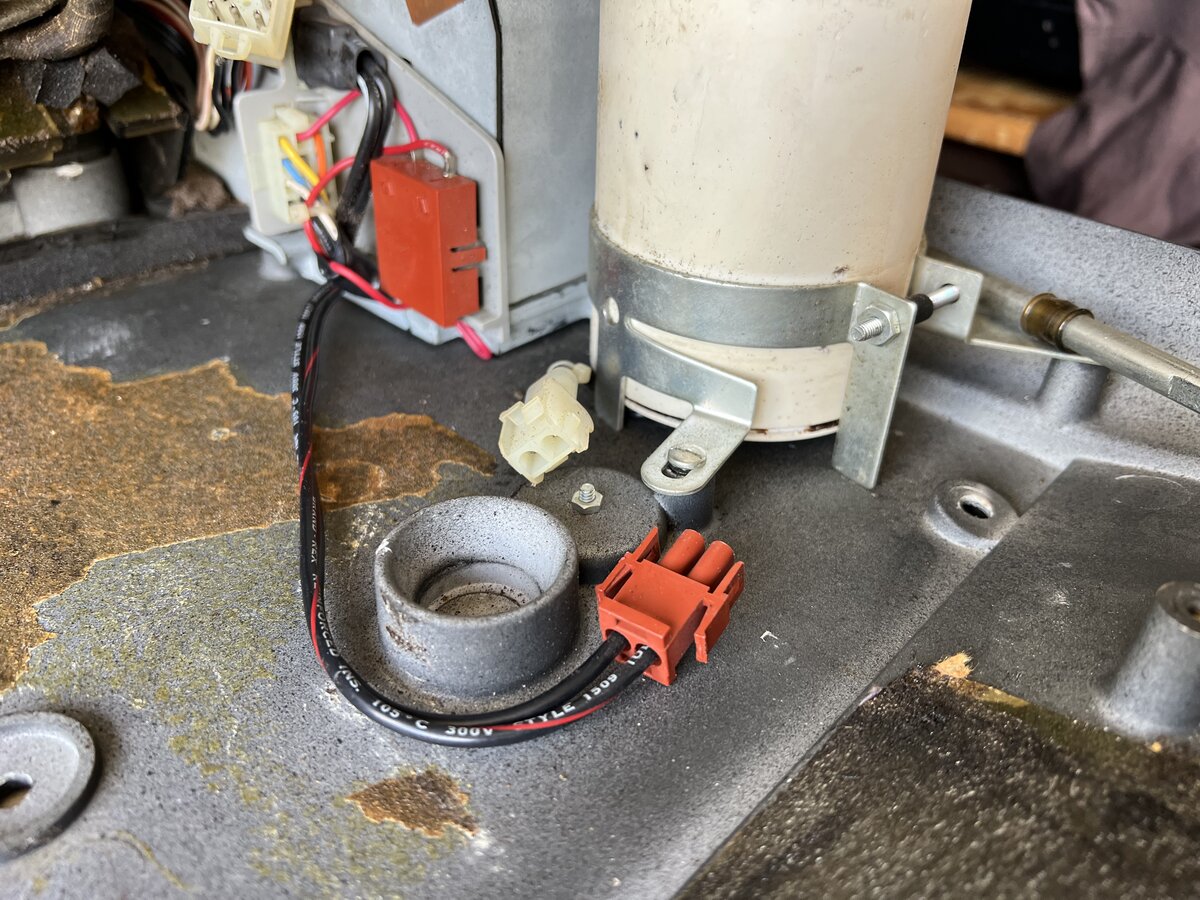
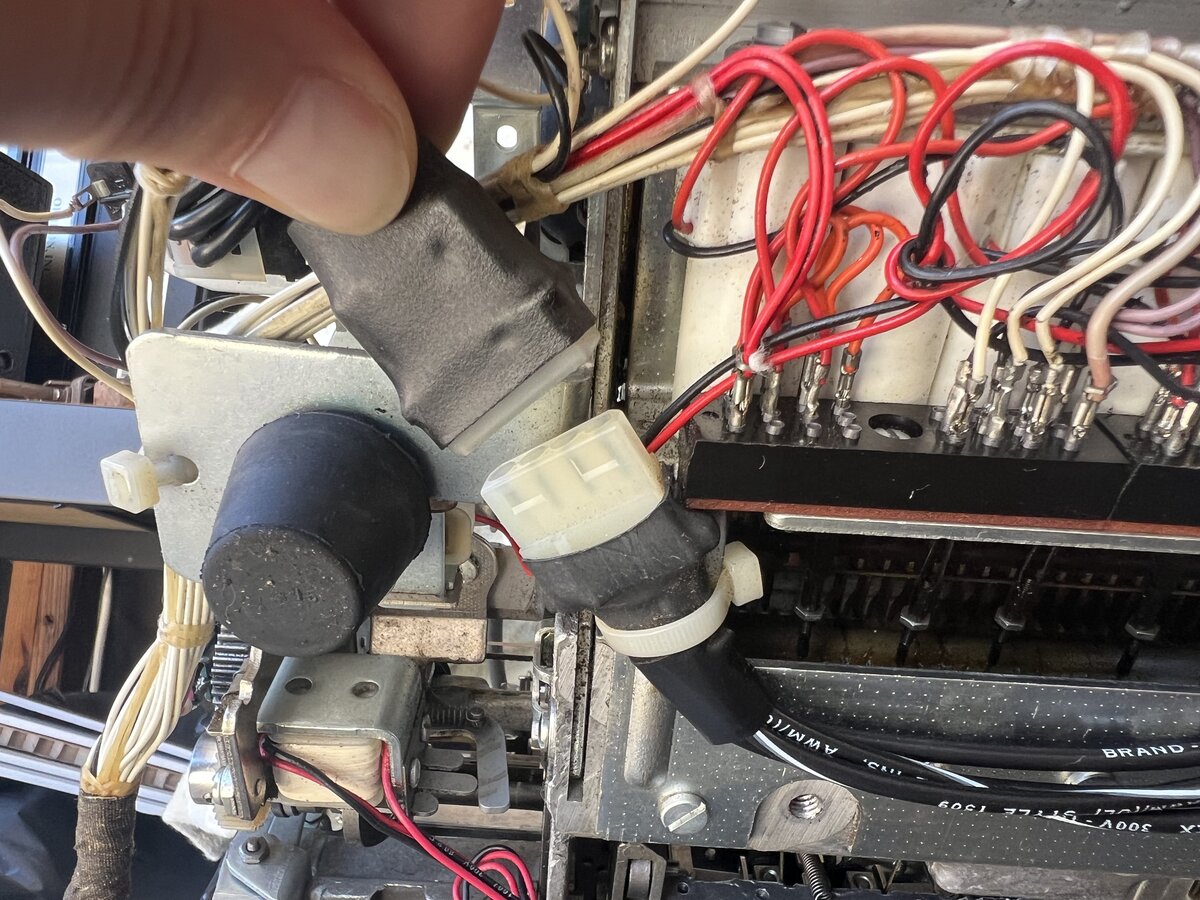
Capacitor
It’s very obvious, opening the machine’s cover, that there is a huge capacitor on the right!
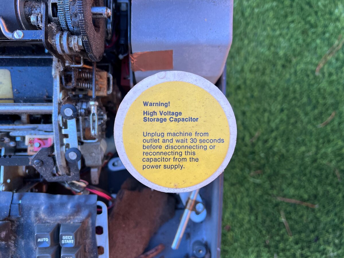
In fact, it is marked as follows:
Warning! High Voltage Storage Capacitor
Unplug machine from outlet and wait 30 seconds before disconnecting or reconnecting this capacitor from the power supply.
I guessed that this capacitor was present to give the machine a chance to power the machine for a while in case of a power outage or the user inadvertently turning off the machine. I think that I was correct, based on a comment I found on YouTube as well as on a discussion thread on Facebook. The feature doesn’t appear to be documented in the manual, however.
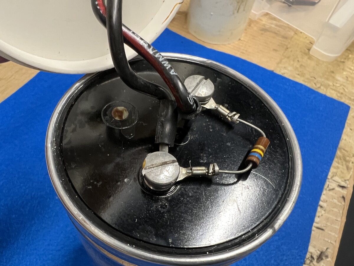
I wanted to know the specs of this capacitor, so I took it out of the machine. But the capacitor was stuck in that white housing. I couldn’t get it out at first, and didn’t want to destroy the housing or puncture the capacitor, which might contain PCBs.
Sleeping on it, I finally managed to open it, as follows:
- I removed the yellow sticker with a plastic blade
- I drilled a hole at the top of the housing, carefully, so that air could come in from the top
- I used penetrating oil from the other side to loosen the capacitor
Finally, I was able to get the capacitor out of the housing.
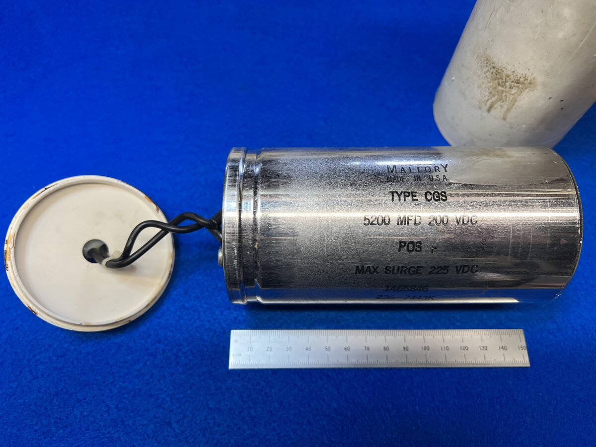
It is a Mallory 5200 µF polarized capacitor, and it is rated at 200 volts. It is beautiful in its silver casing, but those things do not tend to last forever. If the machine ends up working, I will probably plug in a new capacitor.
I measured the voltage from the power supply going to the capacitor (with the capacitor disconnected), and it was 167 V. I also measured the resistor, also disconnected, and normally installed in parallel with the capacitor, at 161 KΩ.
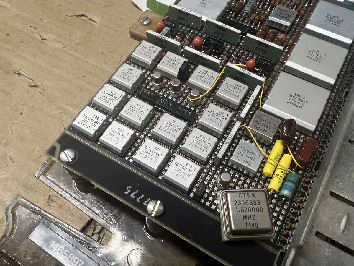
Power supply
This machine, like the other IBM electronic machines (but unlike the plain Selectric) has a sophisticated power supply (PSU). Again, it would be unwise to just turn everything on and hope for the best! If it’s dead or faulty, you want to know beforehand. This is partly why I initially disconnected the planar.
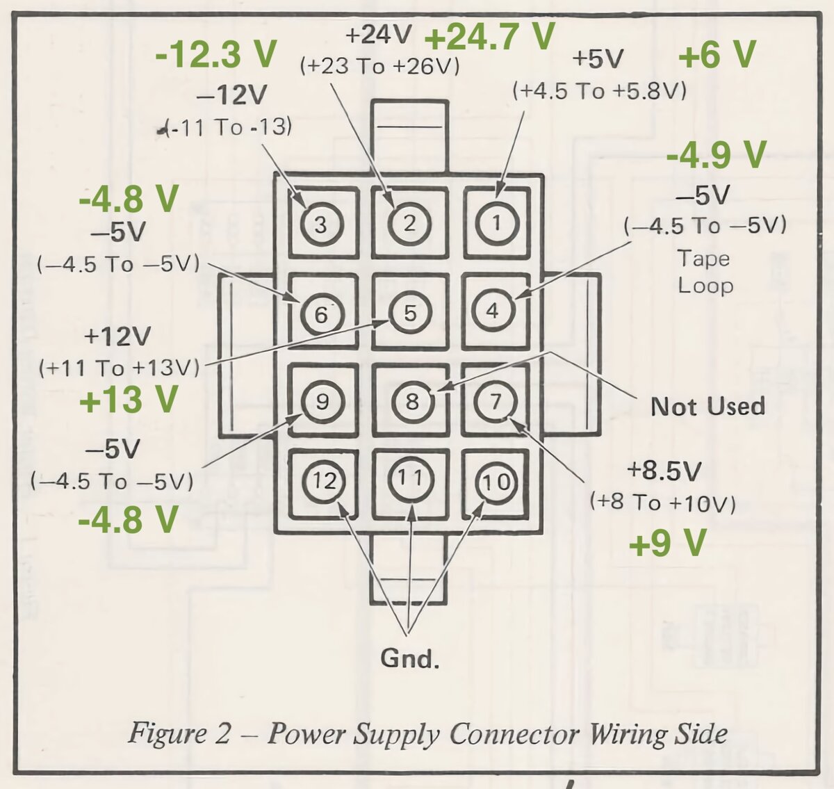
This PSU appears to be almost the same as if not identical to the one in the IBM memory typewriters. It outputs a whole series of voltages for the electronics. It also has a separate connector for the machine’s AC motor.
I measured all the voltages of the power supply against the service manual, as I did for the Memory Typewriter. I found that the voltages were all in range!
I also opened the PSU to clean it.
Initial mechanical work
The carrier was stuck to the left. I managed to move it by running the motor, and activating the leadscrew solenoid by hand. Then I did some cleaning with mineral spirit.
However, I noticed that the tilt tape fell off its wheel.
I asked advice about how to fix that as I don’t want to break the tape. I started by cleaning up a very dirty Selectric II that I had, so I could play with its tilt tape a little. I managed to go through the procedure, which consists in:
- rotating the type element (or rather the post holding it) by hand, which loosens the tape
- using a spring hook, I managed to grab and pull the tape, to get a feel for it
I then did the same on the Electronic Composer, and I managed to get the tape back on the wheel. However, I noticed that, after manually triggering the cycle clutch solenoid a few times, the tape fell off the wheel again. I put it back again but this might have to be investigated further, although it hasn’t happened since then.
The broken toggle switches
As mentioned initially, the machine has a few broken switches: three push switches on the left, as well as two toggle switches.
I have a parts Selectric II which I figured I might be able to use to steal the toggle switches from, if the toggles were compatible. And indeed they are! The replacements are not the correct color, and in addition the Composer’s On/Off switch has an extra marking in the middle which the replacement doesn’t have. But mechanically, they are identical. This will work for now.
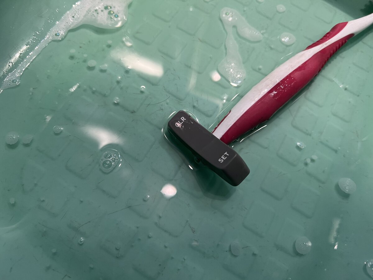
I took out the switches from the parts machine and cleaned them up.
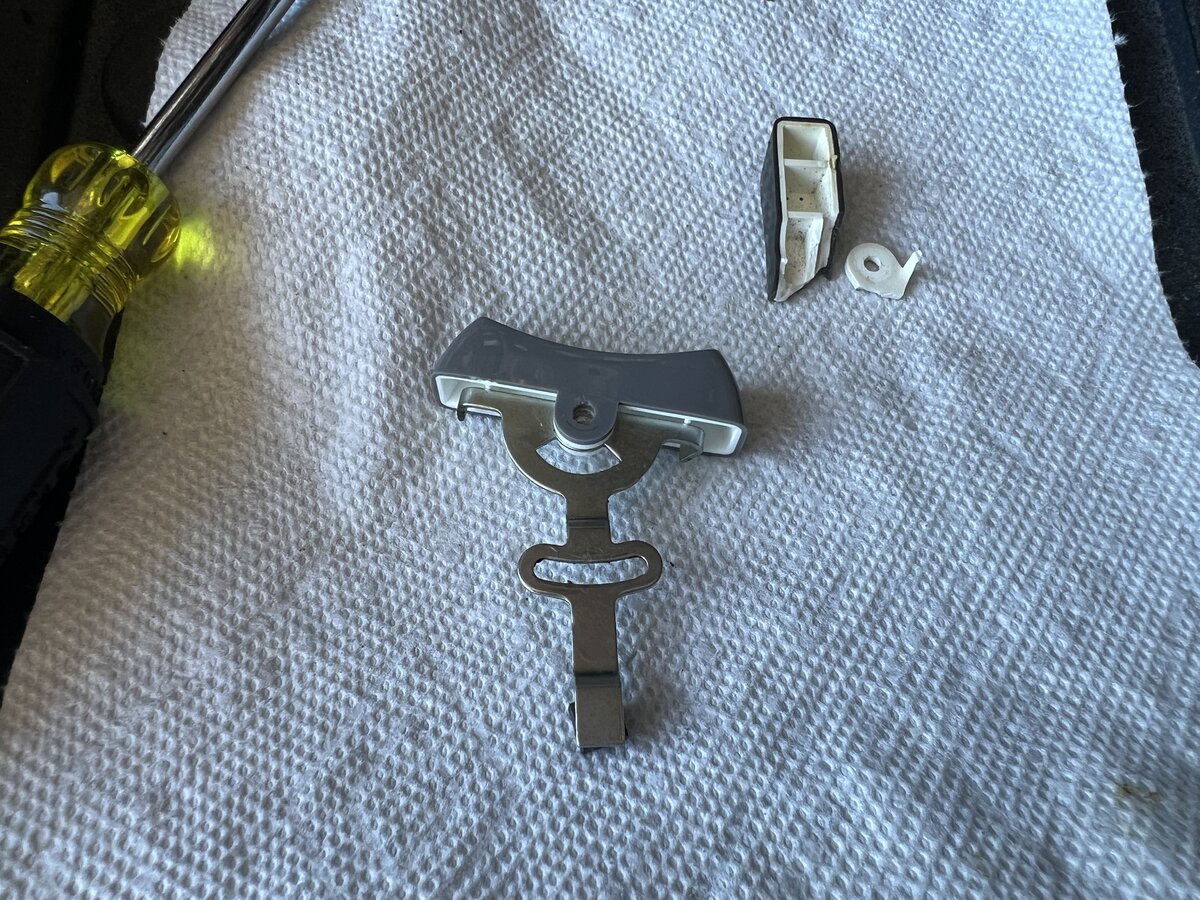
Removing the broken part was easy: remove two C-clips, and wiggle the bottom part out. I checked that the button was fiting.
Putting the parts back was a little harder and I had to unscrew the metal plate holding all the switches to gain some clearance.
The switch is now in place.
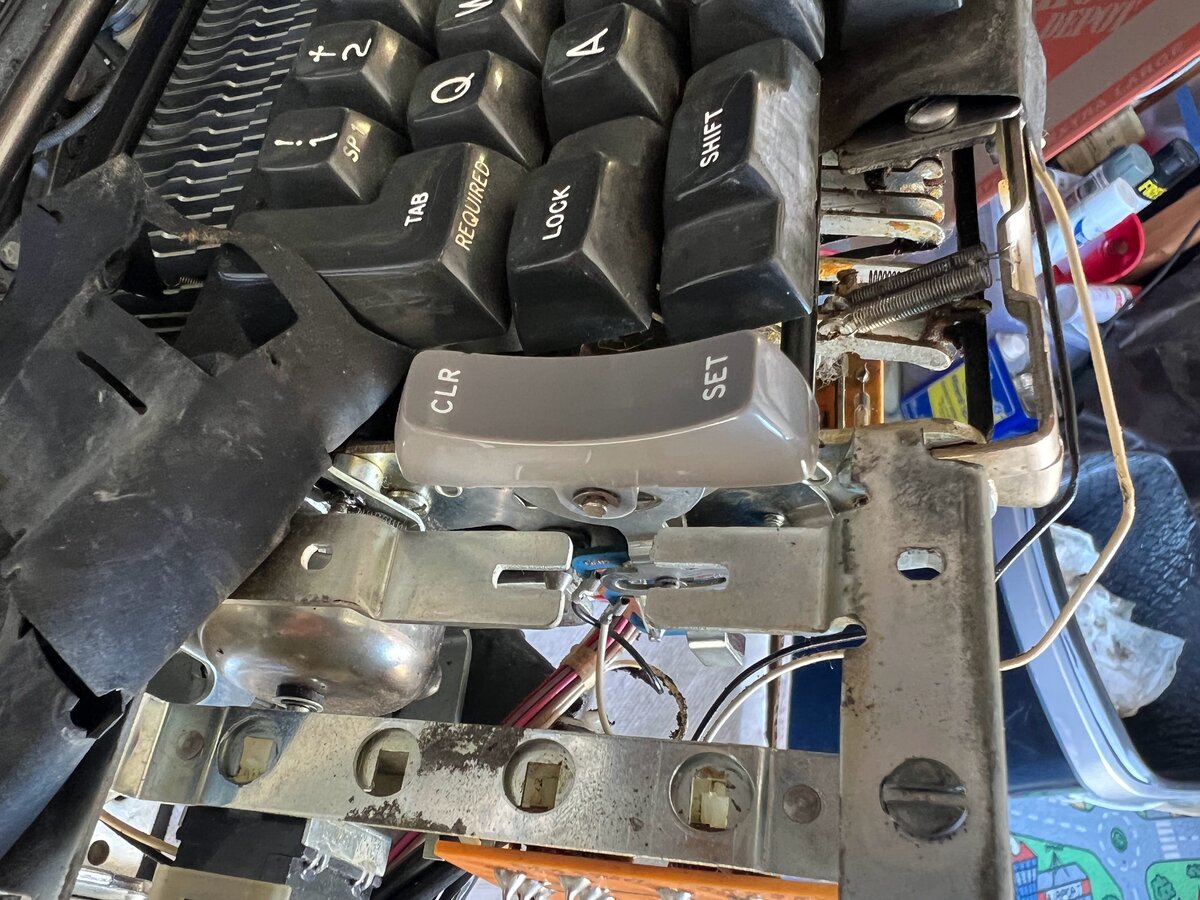
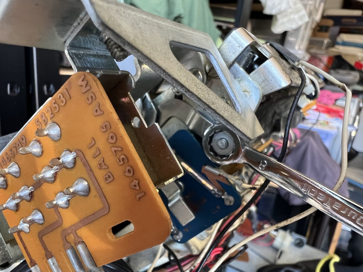
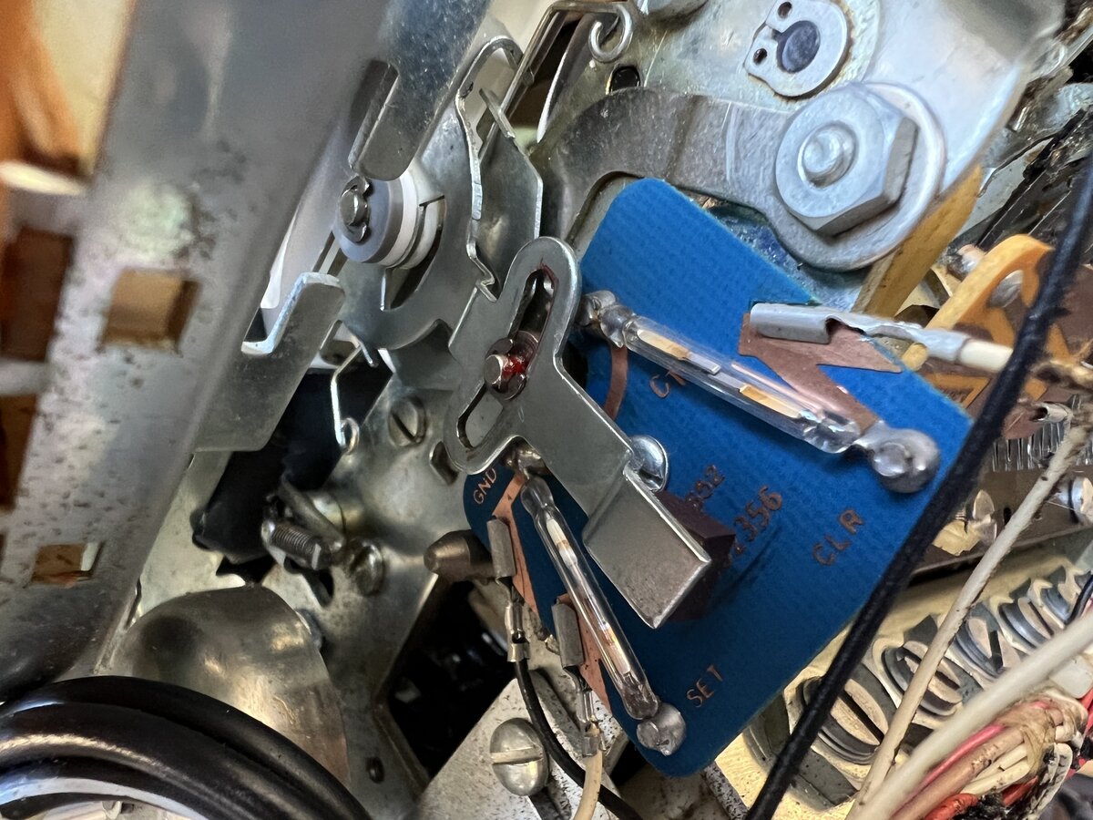
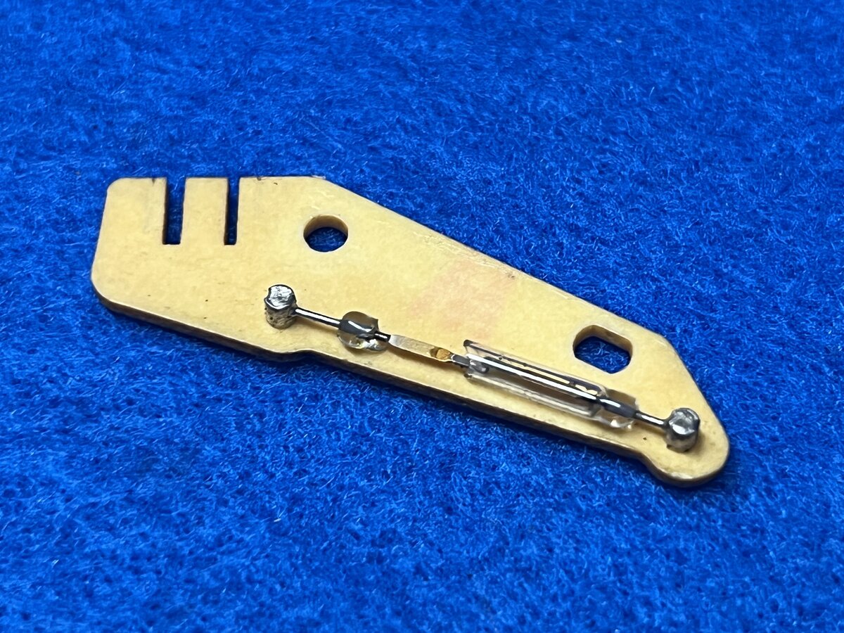
You can see how the tab CLR/SET toggle works: there is a permanent magnet on the metal arm, and when pressing the toggle causes it to swing past one of the two reed switches, which can then detect the action. Unlike with most typewriters, here even the tab positions are set electronically. I find this very neat! I put a drop of grease on the sliding area.
Here is what’s left of the tab CLR/SET switch assembly in the donor Selectric II.
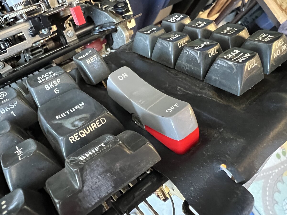
The power switch was even easier to change, as there was no clearance issue and just one C-clip. Here the toggle is mechanically connected to the actual power switch in the machine, like on regular Selectrics.
I haven’t attempted to fix the other switches yet.
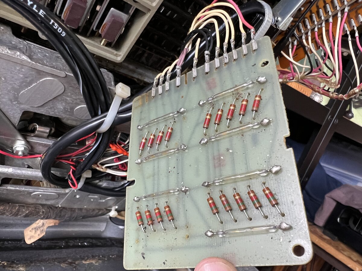
The transmit block
Out of curiosity, I removed the transmit block, which is made of two parts:
- a PCB with 7 reed switches and 18 resistors
- a purely mechanical part with the magnets, which slide as the keyboard is pressed
As I suspected, both parts needed cleaning.
The bottom of the keyboard is full of grease with dirt. That will need serious cleaning.
Here are the clean parts:
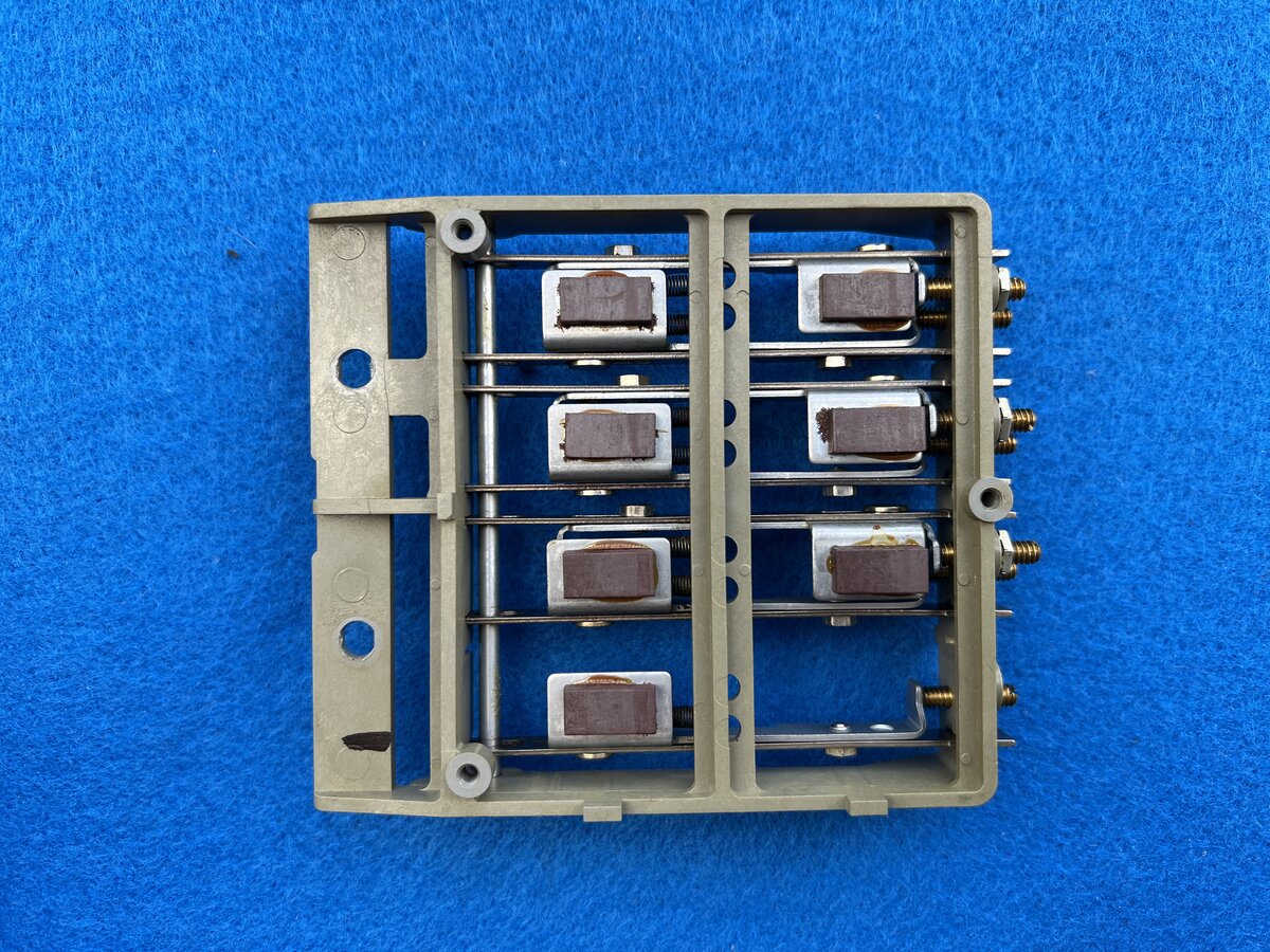
The sliders move easily.
I put this back in place, but I might have to remove it again when cleaning the keyboard. I noticed small cracks in the plastic so I’ll have to be careful. It might be a good idea to reinforce the plastic with some glue or epoxy.
More cleaning of the bottom case
I managed to peel off the front adhesive, which was annoyingly sticky to the touch. It took a little while. The bottom is now clean enough I think.
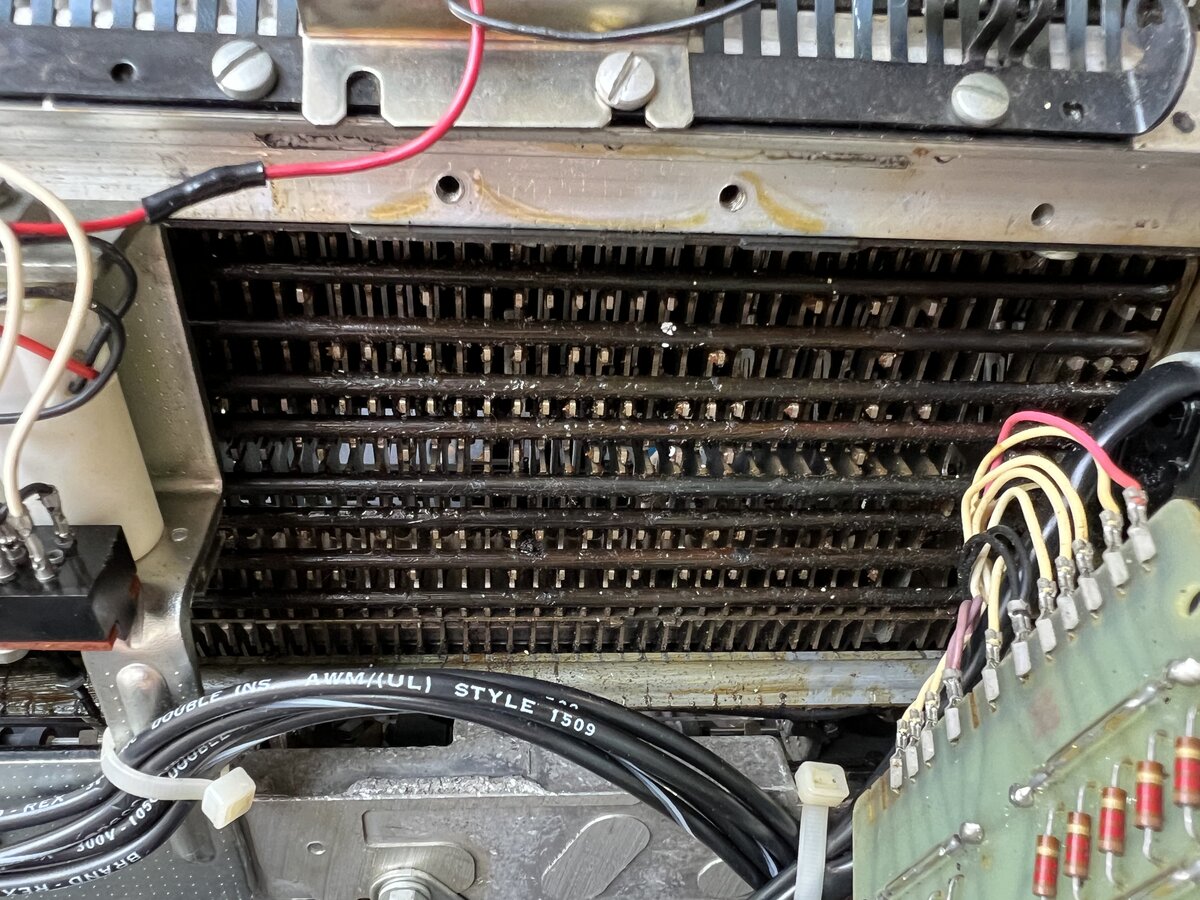
Cleaning under the keyboard
I removed again the transmit block, and I also removed the block with the solenoids so I could do proper cleaning. To do so is a little harder than the transmit block:
- disconnected power cable
- removed cable ties
- disconnected 2 wires
- disconnected 1 wire on the connection block
- finally, remove the 2 screws
The block remains connected, but can be moved a little to the side so that cleaning is possible.
I asked online about whether the bails should be regreased. The answers were split: some say, as the IBM service manuals mention, that you should grease the “filter shaft flutes”, ahd lightly grease the bails where they contact the interposers. But there shouldn’t be too much grease.
There is where I should mention a dumb mistake: I put a gloved finger near the operational shaft while it was running. The glove got caught and the machine stopped abruptly. I turned off the power immediately. I was able to remove the glove by cutting it out, but I was lucky: although the carriage return had stopped working, I managed to figure out quickly how to fix it (there was a slightly bent part). Morality: don’t put your (gloved) fingers near moving parts!
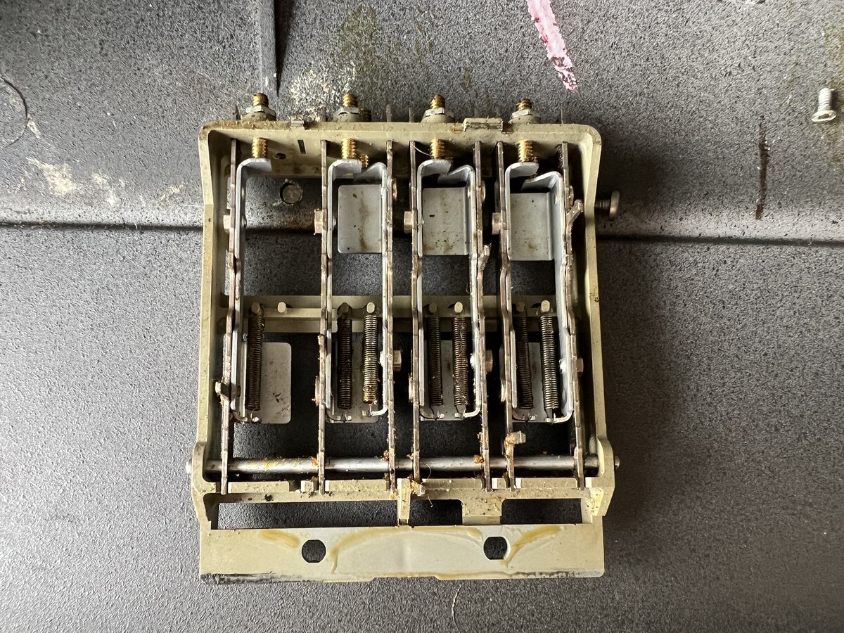
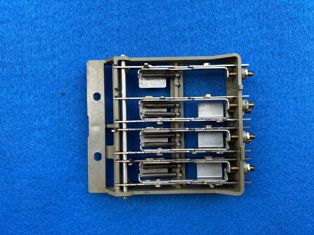
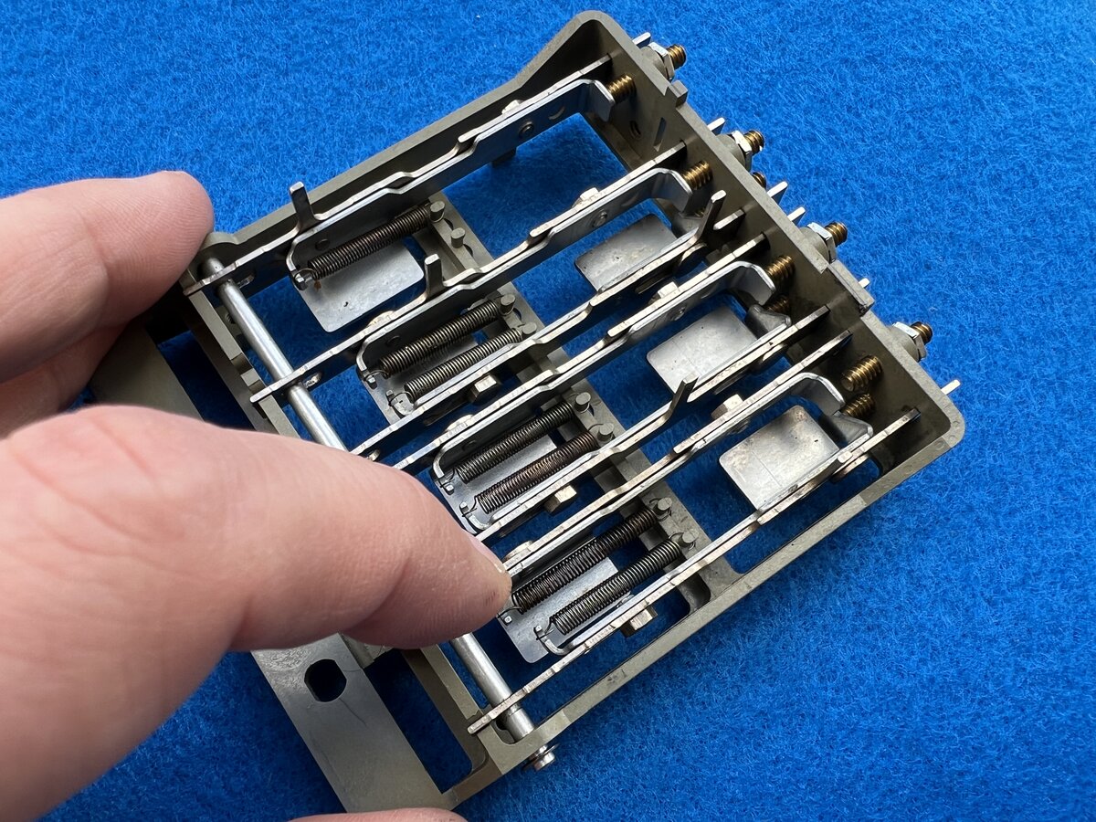
Left switch assembly
I decide to have a look at the left switch assembly, which is the one with the broken push switches. I removed the assembly, which is held by two screws. The assembly is connected to the machine by 4 wires.
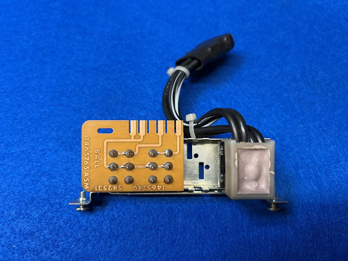
Figured out that the switches could be opened by bending metal. Here is the neat result of the full disassembly:
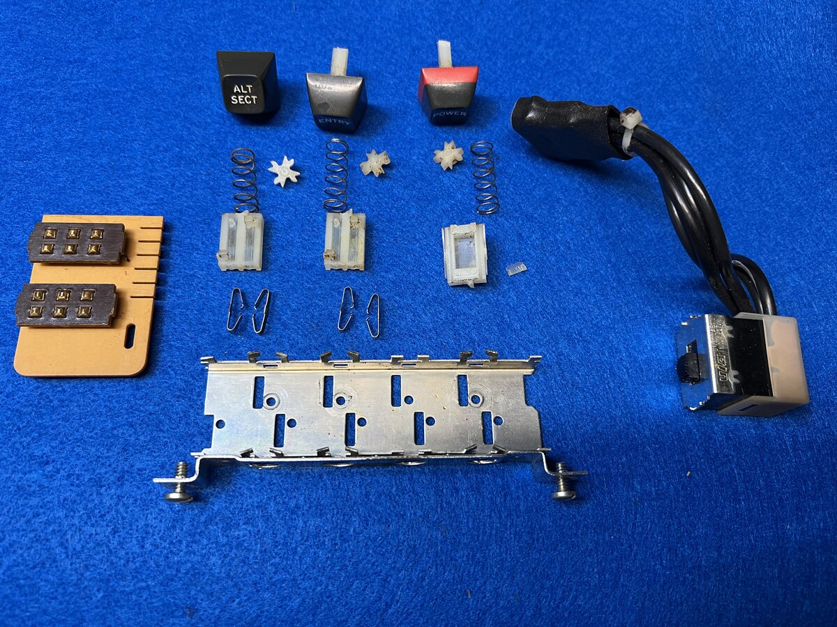
Switches:
- 2 2-positions switches
- custom switches
- each has a pair of sliding metal contacts
- power switch
- 2-positions
- moves what looks like a stock switch
The 3 buttons have their stems broken in a very similar way. The plastic is just fragile. Now the question is how to fix them. Just gluing or expoxying will not suffice. It is imperative to reinforce the stems, probably with metal. The springs are strong. Possibility: drill very small hole in the center, insert epoxied or superglued small metal part. Have to disable the springs while this sets.
Making the carrier move smoothly
As mentioned above, I managed to activate the leadscrew, however it was a little sluggish in some spots. I cleaned more, and used steel wool to remove possible irregularities on the shaft. It might have helped, but I am not entirely sure. This might have to be revisited.
Powering the electronics
I reconnected the planar, with the hope that the electronics would show some sign of life!
When I manually triggered the shift magnet, I could space, hit carriage return, and use the tab function. The tab stopped the leadscrew when hitting the rightmost position! I managed to type some characters, and the escapement moved, although not always reliably. Eventually, though, it stopped working entirely, and I couldn’t get the shift cam up anymore.
However, I discovered that if I turned the motor off and then on again, I could get the machine into a semi-operable state. There were still some issues though, like some letters decoding or printing wrong. Additionally, the on/off light turned off after a while, which is unexpected, but it didn’t seem to affect the rest of the machine; I would expect it to stay on all the time.
Then, I found out what was causing the problem! I noticed that the Shift Feedback Switch board was askew, and the shift arm was pushing or touching it when in uppercase mode. Straightening it out didn’t help, but then I noticed that the Shift Feedback Switch reed switch glass was actually broken!
Luckily, the Memory Typewriter contains the exact same part, intact, so I borrowed it. After replacing it, I found that I could shift more reliably. However, there are still some issues lingering. Spacing still rotates the ball, and some letters continue to print incorrectly.
Troubleshooting the electronics
I took note of most misprinting letters:
| Letter typed | Letter printed |
|---|---|
e | j |
y | ; or y |
u | o or u |
p | q |
] | f |
h | w or h |
l | 7 |
? | shift activated |
z | g |
6 | 6 or 0 |
- | a |
= | no action |
I analyzed the issue using the “Selectric composer font chart”.
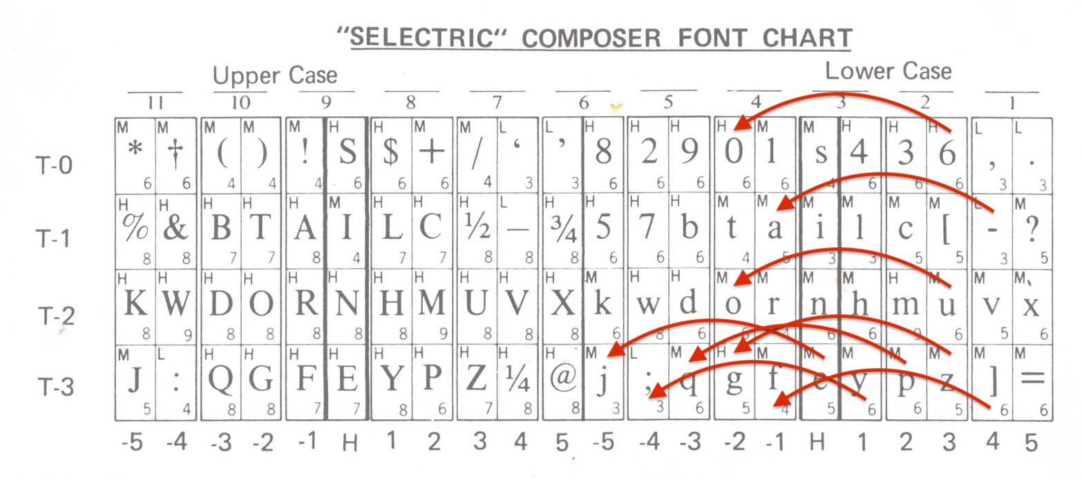
The issue seemed to be with rotation only. I concluded that the issue was with R5. “The negative 5 rotate latch rotates the typehead five units in the clockwise or negative direction”. So R5 was activated in cases it shouldn’t be!
I tried the following:
- disconnecting R5 from the transmit block (no change)
- removing the transmit block PCB and putting it back (still no change)
- measured the resistors: 1.25 kΩ/1.58 kΩ (one to +8.5V +12V, one to GND)
- checked the movement of the magnets, which seemed ok
- measured the voltage of R1, R2, R5 at rest on the transmit block: result: 8.5 V in all cases, which seems right
So at this point, I am a little stuck. I need to check further that R5 link.
Temporary conclusion
I have made some progress:
- determined that the machine was in pretty good shape after all;
- did the initial cleaning;
- determined that the motor and PSU work;
- fixed two broken toggle switches;
- documented the capacitor;
- checked that some electromechanical functions work, by activating the relays by hand;
- put back the planar for a test of the electronics;
- determined that there was a broken reed switch and replaced it;
- established that there is life in the electronics;
- but found an issue related to the R5 signal.
The next steps include:
- figuring out the issue with R5;
- fixing the remaining broken switches;
- greasing/oiling some moving parts;
- fixing and putting back the acoustical hood and paper rest.
The first one of these issues is, of course, major, but there is hope.
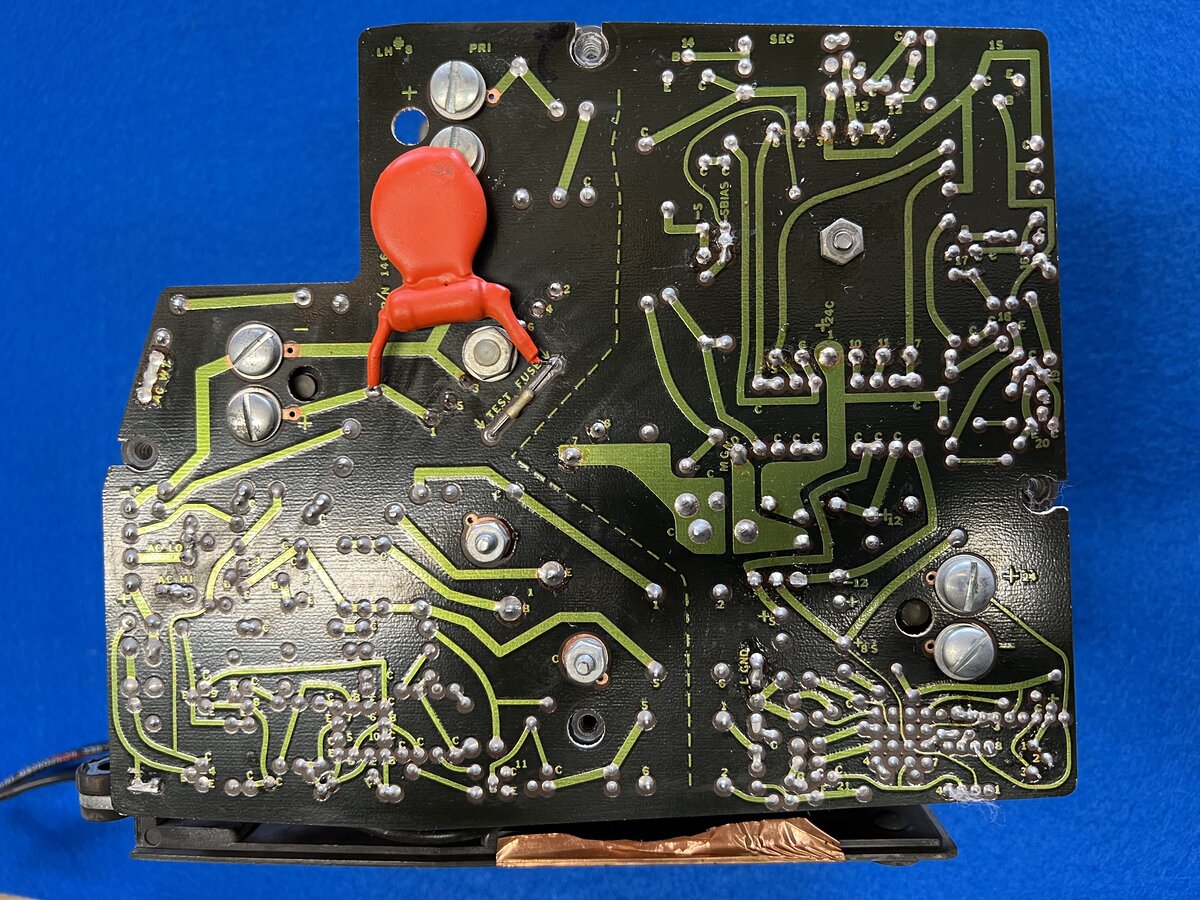
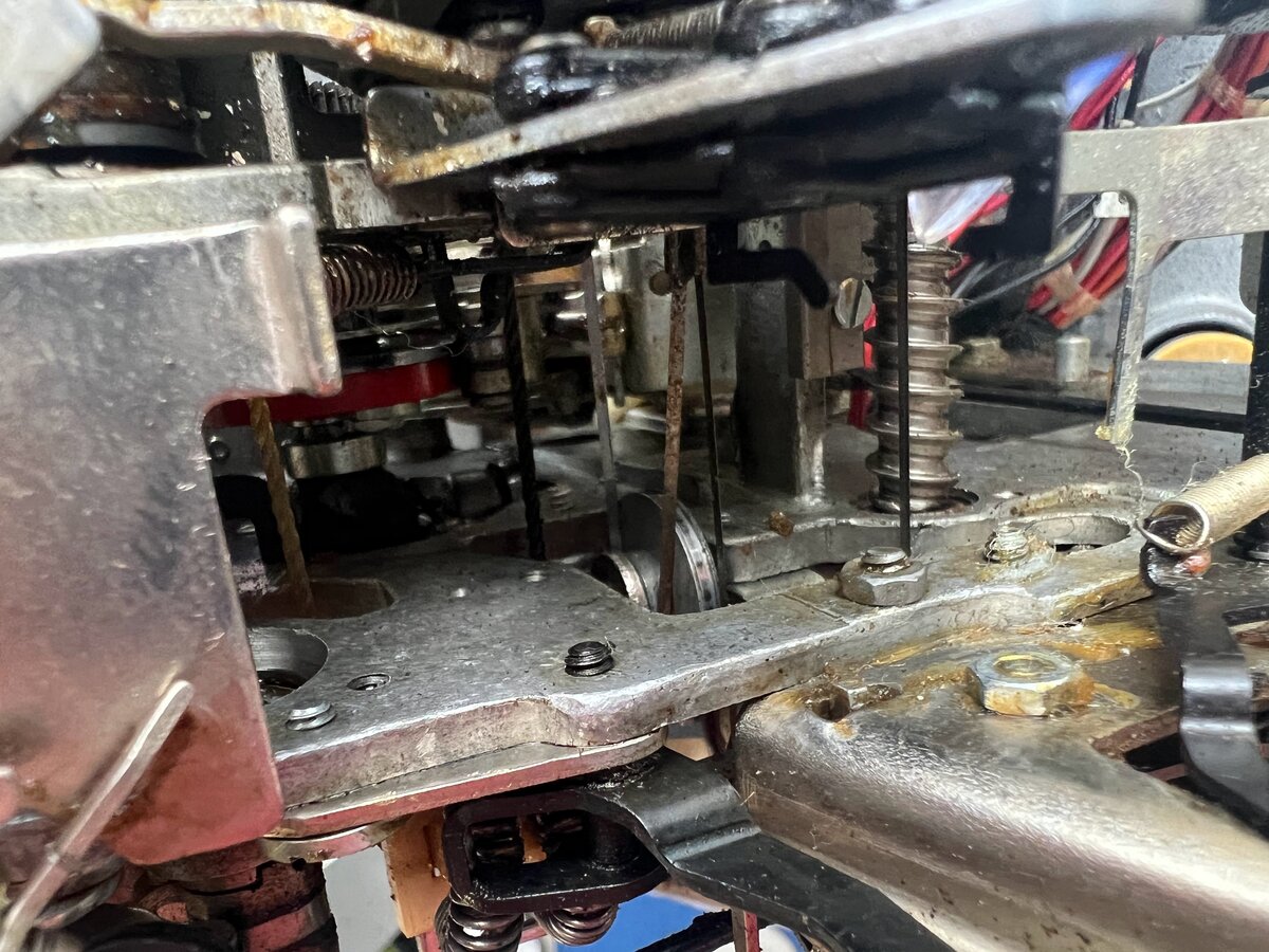
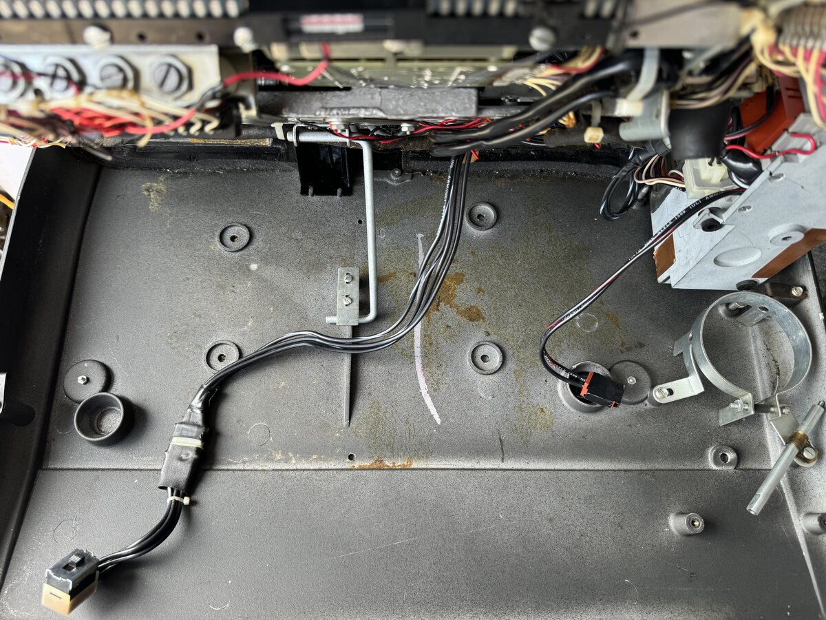
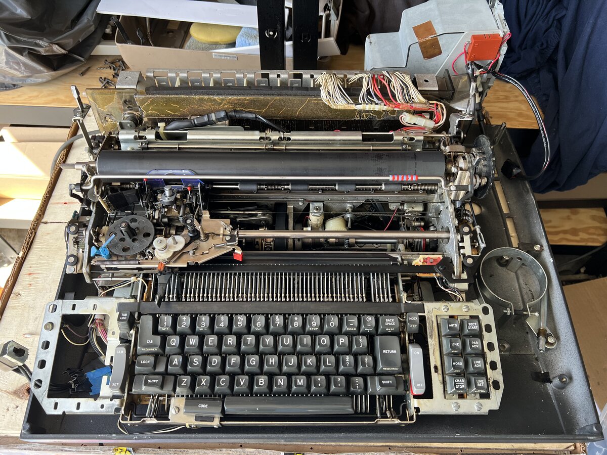
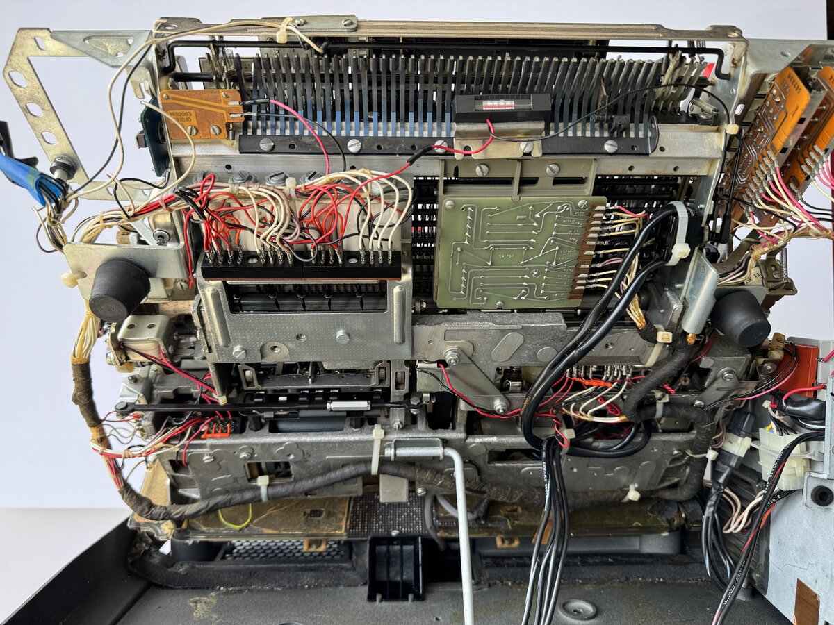
Here is the belly of the machine as of March 2024:
See also
Full photo albums:
- IBM Electronic Selectric Composer (1978) - Part 1
- IBM Electronic Selectric Composer (1978) - Restoration in progress
The ongoing work on the Memory Typewriter:
- The IBM Memory Typewriter
- Restoring an IBM Memory Typewriter - Part 1
- Restoring an IBM Memory Typewriter - Part 2
On the typewriter database (TWDB):
- 1978 IBM Electronic Selectric Composer
- 1969 IBM Selectric Composer
- 1969 IBM Magnetic Tape Selectric Composer
I learned recently that the MT/SC has core memory as part of its electronics! However, it is internal memory for the microprogram, escapement tables, registers, and buffers for running the justification algorithm, not text memory that is accessible by the user. ↩
I have since obtained an electromechanical composer as part of an MT/SC system! ↩
Between the original Selectric Composer and the Electronic Composer, IBM introduced the Magnetic Tape Selectric Composer, which combined a slightly modified Selectric Composer, a large tape drive console, and electronics integrated within a desk. This combination removed the need for typing each line twice to obtain justification, but it required a lot of hardware, including a dedicated recording station. ↩
VariTyper is a company and line of machines I plan to write about separately. ↩
I have since obtained, with another machine, 18 more elements. However, I am still interested in finding more Composer type elements. ↩
The Mag Card/A is another machine that I must write about separately as well! ↩
Comments powered by Disqus.